ISSN 0104-6632 Printed in Brazil
www.abeq.org.br/bjche
Vol. 23, No. 04, pp. 497 - 506, October - December, 2006
BrazilianJournal
of Chemical
Engineering
AN ANALYSIS OF PROCESS HEAT RECOVERY IN
A GAS-SOLID SHALLOW FLUIDIZED BED
A. A. B. Pécora
*and M. R. Parise
School of Mechanical Engineering, State University of Campinas, Unicamp, Zip Code 13083-970, Campinas - SP, Brazil
Phone: +55-019-3788-3374, Fax: +55-019-3289-3722 E-mail: [email protected]
(Received: March 3, 2005 ; Accepted: August 21, 2006)
Abstract - This work presents an experimental study of a continuous gas-solid fluidized bed with an immersed horizontal tube. Silica sand (254µm diameter) was used as solid particles and air was used for fluidization in a 900mm long and 150mm wide heat exchanger. Measurements were made under steady state conditions for a solid particle mass flow rate from 14 to 95kg.h-1 and a number of baffles from 0 to 8. Results showed that the heat transfer coefficient increases with the solid particle mass flow rate and with the number of baffles, suggesting that these are important factors to be considered in the design of such equipment. An empirical correlation for the heat transfer coefficient is proposed as a function of solid particle and gas mass flow rate, number of baffles and gas velocity.
Keywords: Shallow fluidized bed; Experimental work; Heat transfer coefficient.
INTRODUCTION
Fluidized beds are commonly employed in chemical, biochemical and petrochemical industries in processes such as hydrocarbon cracking, drying of solid particles, combustion and gasification of coal and biomass, thermal treatment of metals, synthesis reactions and coating of particles.
In order to optimize processes, heat recovery from gas or solid particles that leave the reactors at high temperatures is recommended. A fluidized bed heat exchanger with immersed tubes is commonly employed for such a purpose.
Gas-solid fluidized systems are characterized by temperature uniformity and high heat transfer coefficients due to the intense mixture of the solid material with the gas bubbles normally present.
A shallow fluidized bed is continuously operated and typically characterized by a height-to-length ratio far below one and a length-to-width ratio of at least 5 as suggested by Bülau and Hallström (1998). Applications of shallow fluidized beds include the
drying and heating/cooling of solid particles, mainly due to the advantage of the small drop in bed pressure. This equipment is recommended by Elliot and Holme (1976), Aihara et al. (1993) and Virr and Willians (1985).
The design of fluidized bed heat recovery equipment involves the determination of gas-particle and suspension-wall heat transfer coefficients. Heat transfer between an immersed surface and a gas-solid fluidized bed consists of three additive components: particle convection, gas convection and radiation. The influence of each component is the subject of a lot of research and the results show the important effect of particle diameter and bed temperature on the heat transfer process (Chauk and Fan, 1998). The literature shows a considerable amount of correlations for these coefficients, but it is important to notice that as they are very dependent on particle and gas properties besides gas flow rate, they must be applied carefully.
diameter (dp) on the bed-to-tube heat transfer
coefficient (hb). They observed an increase in hb with
an increase in Tb and uo and with a decrease in dp.
Khan and Turton (1992) studied the influence of angular position (
θ
), superficial gas velocity (uo),particle diameter and type of solid material on hb.
They observed an increase in hb with an increase in
uo and with a decrease in dp. They obtained the
largest bed-to-tube heat transfer coefficients at 90o and 120o from the bottom of the tube.
Ndiaye et al. (1996) also studied the variation in bed-to-tube heat transfer coefficient with bed temperature, verifying that hb increases with Tb for
all conditions tested.
All this experimental work is related to batch conditions where there is temperature uniformity inside the fluidized bed. A review of the literature shows little research on fluidized beds with a continuous flow of solid particles along the heat exchanger length in spite of their technological importance in processes such as drying and heat recovery. The movement of the solid particles, which is induced by the rising bubbles and axial pressure gradient, may have a distinct pattern near the tube wall, which will determine the heat transfer coefficient.
A continuous solid flow is found in work by Tardin et al. (1997), Rodriguez (1998) and Rodriguez et al. (2002). Tardin et al. (1997) studied experimental data on a nonisothermal fluidized bed heat exchanger with an immersed tube whose main function was the heat recovery from ashes produced by a pilot scale plant of a 1MW circulating fluidized bed boiler. The results were applied to verify the correlations for the bed-to-tube heat transfer coefficient available in the literature. According to the authors, the correlation of Molerus et al. (1995) were in good agreement with experimental data, with less than 20% deviation.
Rodriguez (1998) studied the influence of particle diameter and solid particle mass flow rate on the bed-to-tube heat transfer coefficient in a shallow fluidized bed heat exchanger with five immersed tubes. The authors verified that hb decreases with the
increase in particle diameter and increases with the increase in solid particle mass flow rate. It was also observed that hb decreased between the solid inlet
and the solid outlet positions. Rodriguez et al. (2002) conducted experiments in order to verify the influence of the presence of baffles inside the fluidized bed on the heat transfer process. They observed that hb increases in the presence of baffles.
The present experimental study was conducted in the same experimental apparatus as that used by
with just one immersed tube inside the bed in order to improve the control of water flow rate through the tube. Experiments were carried out using a larger range of solid particle mass flow rates and number of baffles than in previous work. An empirical correlation for the heat transfer coefficient in a bubbling shallow fluidized bed heat exchanger is proposed from experimental results.
EXPERIMENTAL SETUP
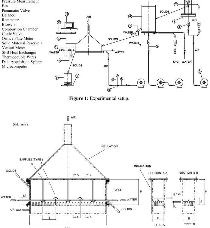
The experimental system, as outlined in Figure 1, consists of three main components: a bin for the sand particles, a fluidized bed combustion chamber where solid particles were heated and a bubbling fluidized bed heat exchanger where solid particles were cooled by air and by water flowing inside an immersed tube in the bed.
A pneumatic valve was used to feed the combustion chamber. A conical feeding valve with internal cooling was used to feed the heat exchanger with hot solid particles from the combustion chamber. After heat recovery, the cold sand left the heat exchanger for a solid reservoir to be reused.
Bed temperatures along the heat exchanger length and inside the combustion chamber were measured with type K thermocouples connected to a data acquisition system. Type K thermocouples were immersed in the fluidized bed, 0.02m above the tube. It was assumed that the distance between tube and thermocouples was large enough to assure that the measured values correspond to the bed temperature. Temperatures of the solid particles and air flows were also measured by type K thermocouples at the entrance and at the exit of the heat exchanger. Water temperature measurements at the inlet and outlet of the heat exchanger were made by type T thermocouples. Pressure measurements were performed with a workbench of U tubes connected to an orifice plate meter and a calibrated Venturi meter to measure air and water mass flow rates, respectively.
An Analysis of Process Heat Recovery 499
Figure 1: Experimental setup.
SOLIDS
Lf WATER
AIR
A B
S
( a ) L
A B
BAFFLES (TYPE ) DIM. ( mm )
B A
AIR
SECTION A-A SECTION B-B
TYPE B B
( b ) TYPE A SOLIDS
WATER Ø 6.5
H
Lj = 20
Lj
B
( c ) Lf
H INSULATION
INSULATION
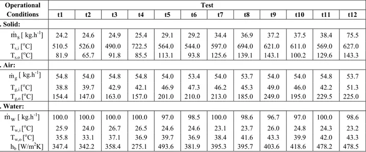
Figure 2: Heat exchanger with 5 baffles: (a) direction of solid material indicated by the arrows; (b) low baffle; (c) high baffle.
WATER
9 3
8
P P
P
10 12
WATER 11
P
SOLIDS
P
13 14
WATER
SOLIDS
AIR
WATER AIR
7 6
5 WATER
P
LPG SOLIDS
3
4 2
AIR AIR
1
WATER
9 3
8
P P
P
10 12
WATER 11
P
SOLIDS
P
13 14
WATER
SOLIDS
AIR
WATER AIR
7 6
WATER AIR
7 6
5 WATER
P
LPG
5 WATER
P
LPG SOLIDS
3
4 2
AIR AIR
1
P Pressure Measurement 1 Bin
2 Pneumatic Valve 3 Balance 4 Rotameter 5 Blowers
6 Combustion Chamber 7 Conic Valve 8 Orifice Plate Meter 9 Solid Material Reservoir 10 Venturi Meter
conditions for a solid mass flow rate from 14 to 95kg.h-1 and a fixed bed height of 100mm. The length/width ratio of the heat exchanger makes sure that there is plug flow for the solid material along the heat exchanger length.
Type T thermocouples were calibrated against a standard glass thermometer considering 10 points in the temperature range of 0 to 100oC. The true value of water temperature is believed to lie within ±0.1oC of the indicated value with a confidence level of 95%. The maximum uncertainty with a confidence level of 95% for type K thermocouples was
The Venturi meter was calibrated with a balance and a chronometer by measuring the weight of the amount of water flowing through the heat exchanger for a given time interval. The estimated uncertainties of the balance and chronometer were ±1g and ±0.5s, respectively.
Uncertainties in tube diameter, tube length and materials properties are not considered in the uncertainty analysis.
Operational conditions and experimental results for heat transfer coefficient for each experimental test are presented in Tables 1 to 3.
Table 1: Operational conditions and hb results for the heat exchanger configuration
without baffles (nb= 0) – tests 1 to 12.
Test Operational
Conditions t1 t2 t3 t4 t5 t6 t7 t8 t9 t10 t11 t12
. Solid:
s
m [ kg.h-1] 24.2 24.6 24.9 25.4 29.1 29.2 34.4 36.9 37.2 37.5 38.4 75.5
Ts,i [ o
C] 510.5 526.0 490.0 722.5 564.0 544.0 597.0 694.0 621.0 611.0 569.0 627.0
Ts,o [oC] 81.9 65.7 91.8 85.5 113.1 93.8 125.6 139.1 143.1 100.2 129.6 143.3
. Air:
g
m [ kg.h-1] 54.8 54.0 54.8 54.8 54.0 53.4 54.0 53.7 54.0 54.0 54.8 53.7
Tg,i [oC] 38.8 39.7 42.9 42.1 46.9 47.3 46.2 45.3 49.0 46.0 42.2 51.3
Tg,o [oC] 154.4 147.0 163.0 157.0 201.0 210.0 213.0 185.0 249.0 195.0 229.5 225.0
. Water:
w
m [ kg.h-1] 100.0 100.0 100.0 100.0 97.0 98.5 100.0 98.6 96.7 97.0 100.0 98.6
Tw,i [oC] 25.9 24.0 26.7 26.5 24.6 24.6 23.1 23.7 26.0 24.8 24.3 23.2
Tw,o [oC] 35.8 33.1 37.1 36.9 39.7 36.9 38.4 41.6 43.3 39.9 42.0 43.3
hb [W/m2K] 347.4 342.2 358.4 275.1 493.6 381.9 395.3 395.7 403.6 418.6 478.2 478.5
Table 2: Operational conditions and hb results for the heat exchanger configuration
with five baffles (nb = 5) – tests 13 to 18.
Operational Conditions Test
t13 t14 t15 t16 t17 t18 . Solid:
s
m [ kg.h-1]
13.8 20.4 31.8 43.8 80.4 94.8
Ts,i [oC] 579.0 602.0 619.0 624.0 650.0 670.0
Ts,o [oC] 87.7 137.7 59.1 86.1 313.1 350.2
. Air:
g
m [ kg.h-1] 42.0 42.0 42.0 42.0 42.0 42.0
Tg,i [oC] 37.4 48.8 37.8 34.3 43.5 41.2
Tg,o [oC] 137.0 203.0 122.0 150.0 312.0 319.0
. Water:
w
m [ kg.h-1] 93.9 93.9 93.9 93.9 93.2 93.2
Tw,i [ o
C] 25.5 24.6 24.6 25.7 20.2 20.2
Tw,o [ o
C] 41.8 47.3 39.2 46.0 71.5 74.0
An Analysis of Process Heat Recovery 501
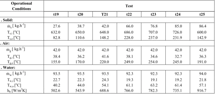
Table 3: Operational condition and hb results for the heat exchanger configuration
with eight baffles (nb= 8) – tests 19 to 25.
Operational
Conditions Test
t19 t20 T21 t22 t23 t24 t25 . Solid:
s
m [ kg.h-1] 27.6 38.7 42.0 66.0 76.8 85.0 86.4
Ts,i [ o
C] 632.0 650.0 648.0 686.0 707.0 726.0 600.0
Ts,o [ o
C] 82.8 110.6 148.2 228.0 237.0 231.9 142.9
. Air:
g
m [ kg.h-1] 42.0 42.0 42.0 42.0 42.0 42.0 42.0
Tg,i [oC] 38.4 36.2 41.6 38.1 34.6 32.7 36.3
Tg,o [oC] 155.0 170.0 220.0 249.0 254.0 245.0 191.0
. Water:
w
m [ kg.h-1] 93.5 93.5 93.5 92.3 92.3 92.3 94.0
Tw,i [oC] 22.7 22.3 24.3 19.3 19.1 19.2 21.8
Tw,o [oC] 40.2 44.0 54.1 61.1 63.2 61.4 57.1
hb [W/m2K] 502.6 543.9 688.6 766.0 782.3 735.1 916.7
BED-TO-TUBE HEAT TRANSFER COEFFICIENT, hb
Coefficient hb was obtained from experimental
data on mass flow rates and inlet and outlet temperatures of the three currents in the heat exchanger: solid, air and water.
Supposing a heat exchanger is insulated from its surroundings, the energy balance in a control volume involving the equipment would provide
s g w
q = +q q (1)
where q , q , q s g w are given by
(
)
s s s s,i s,o
q =m c T −T (2)
(
)
g g g g,o g,i
q =m c T −T (3)
(
)
w w w w,o w,i
q =m c T −T (4)
The overall coefficient of heat transfer (U) between gas-solid suspension and water can be found by equation (5):
w
q =U.A.LMTD (5)
where the heat transfer area (A) and the logarithmic mean temperature difference (LMTD) are given by
t
A= π.d .L (6)
s,i w,o s,o w,i
s,i w,o
s,o w,i (T T ) (T T ) LMTD
T T ln
T T
− − −
=
−
−
(7)
The solid exit temperature (Ts,o) was assumed to
be equal to the bed temperature at the solid outlet position (Tb,o). This procedure is based on the
hypothesis of almost instantaneous thermal equilibrium between gas and solid particles. This hypothesis is reasonable for particles smaller than 400µm, as discussed by Molerus (1997).
The average bed-to-tube heat transfer coefficient can be calculated by equation (8):
t t t
b w t,i t t,i
d d d
1 1 1
ln h U h d 2k d
= − +
(8)
w
t,i h
d
= (9)
where, n = 0.4 is used for the heating process. Equation (9) has been confirmed experimentally for 0.7 ≤Pr≤160, Re ≥ 10000 and L/dt,i ≥ 10.
The Nusselt number for the heat transfer between gas-solid suspension and tube wall can be calculated with equation (10):
b t
g
h d Nu
k
= (10)
The uncertainty analysis for the gas-solid heat transfer coefficient (hb) was calculated with equation
(11) (Holman, 1994), where µ(yi) represents all the
uncertainties derived from the measurement of yi.
The yi variables in this equation are the water mass
flow rate and the solid and water temperatures at the inlet and outlet of the heat exchanger as shown by equations (4) to (9).
( )
2( )
2 b 2
b i
i i
h
h . y
y
∂
µ = µ
∂
∑
(11)RESULTS AND DISCUSSION
The bed temperature along the heat exchanger length showed a decreasing profile from the solid inlet to the solid outlet position as discussed previously by Parise (2000) and Rodriguez et al. (2002). This is a typical profile for bubbling shallow fluidized beds.
The presence of baffles increases the total heat transfer rate, resulting in a low solid temperature at the exit of the heat exchanger. This result is attributed to the increase in the solid residence time inside the heat exchanger due to the increased path of the solid particles due to the baffles.
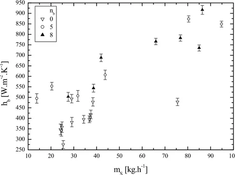
Figure 3 shows the influence of the solid particle mass flow rate on the heat transfer coefficient obtained by the methodology described. The influence of the number of baffles can also be verified in this figure, in addition to the vertical lines representing experimental uncertainties in the
bed-The maximum uncertainty obtained for hb was of
about 8%, which is quite acceptable for gas-solid fluidized beds.
For a fixed number of baffles, it was observed that the heat transfer coefficient increases with the increase in the solid particle mass flow rate. This behavior can be explained by the increase in the horizontal component of the solid velocity, increasing the contribution of particle convective in the heat transfer process, as observed by Ivanyutenko (1992), Rodriguez (1998) and Rodriguez et al. (2002). The presence of baffles inside the fluidized bed increases the bed-to-tube heat transfer coefficient as shown in Figure 3. This behavior can be attributed to acceleration of the particles as they cross the windows formed by the baffles, which increases the particle convective coefficient. However, no significant differences between experiments with 5 and 8 baffles are observed, suggesting that there is an optimal number of baffles for application for heat recovery purposes.
With hb experimental results from this work and
from work by Rodriguez et al. (2002), a correlation for bed-to-tube Nusselt number was proposed as a function of three dimensionless ratios: solid particle mass flow rate and gas flow rate
(
m / ms g)
, heat exchanger length and distance between baffles (L/S) and superficial gas velocity and superficial gas velocity under a condition of minimum fluidization (uo/umf):0.31 0.12 0.23
s o
b
g mf
m L u
Nu 98.35
m S u
−
=
(12)
The correlation coefficient for equation (12) was 0.91 and was obtained for 0.33≤m / ms g≤2.26; 1≤L / S≤9; 3.70≤u / uo mf ≤6.35. As shown in Figure 4 the values predicted by equation (12) were in good agreement with experimental data and with work by Rodriguez (1998) and Tardin et al. (1997) within 20%. The negative coefficient obtained for the uo/umf ratio was expected because the tests were
performed for uo/umf > 3 and as uo increases the
An Analysis of Process Heat Recovery 503
10 20 30 40 50 60 70 80 90 100 250
300 350 400 450 500 550 600 650 700 750 800 850 900 950
nb 0 5 8
h b
[W
.m
-2 .K -1 ]
mS [kg.h-1]
Figure 3: Bed-to-tube heat transfer coefficient for all the tests performed.
0.4 0.5 0.6 0.7 0.8 0.9 1.0 1.1 1.2 1.3 1.4 30
40 50 60 70 80 90 100 110 120 130 140
- 20 % + 20 %
Present work Equation 12 Tardin et al. [1997] Rodriguez et al.[2002]
N
u b
[mS/mg]0.31[L/S]0.12[uo/umf]-0.23
Figure 4: Comparison of the proposed correlation with the experimental data.
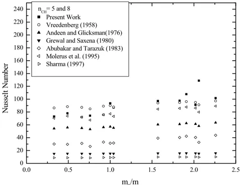
Figures 5 and 6 show the bed-to-tube Nusselt number (Nub), obtained experimentally and also
from some correlations in the literature, applied to experimental data. Significant differences between the values obtained can be observed, showing the complexity of fluidized beds and the influence of geometry and operational conditions on the phenomena involved. Lower deviations are observed for the correlation of Andeen and Glicksman (1976) concerning the heat exchanger without baffles. Figure 6 shows that the Molerus et al. (1995)
correlation was the best one for experiments with 5 and 8 immersed baffles up to
(
m / ms g)
=1. Vreedenberg’s correlation showed the best results for(
m / ms g)
>1, but it can be observed that values in the0.40 0.45 0.50 0.55 0.60 0.65 0.70 0.75 0
20 40 60 80 100 120 140 160 180 200 220 240
N
u
ss
el
t N
u
m
b
er
m
S/mg
nCH=0 Present Work Vreedenberg (1958) Andeen and Glicksman(1976) Grewal and Saxena (1980) Abubakar and Tarazuk (1983) Molerus et al. (1995) Sharma (1997)
Figure 5: Comparison between experimental results (nch=0) and results obtained
with some correlations from the literature.
0.0 0.5 1.0 1.5 2.0 2.5
0 20 40 60 80 100 120 140 160 180 200 220 240
N
u
ss
el
t N
u
m
b
er
m
S/mg nCH= 5 and 8
Present Work Vreedenberg (1958) Andeen and Glicksman(1976) Grewal and Saxena (1980) Abubakar and Tarazuk (1983) Molerus et al. (1995) Sharma (1997)
Figure 6: Comparison between experimental results (nch=5and 8) and results
An Analysis of Process Heat Recovery 505
CONCLUSIONS
The analysis of experimental results produced the following conclusions:
The bed-to-tube heat transfer coefficient increased considerably with the increase in solid particle mass flow rate as well as with the presence of baffles, in agreement with result of Rodriguez (1998) and Rodriguez et al. (2002).
A small difference in hb between tests performed
with 5 and with 8 baffles was observed, indicating that there is a maximum for number of baffles which no more significant increase in the heat transfer coefficient are observed.
An empirical correlation is proposed to determine the bed-to-tube heat transfer coefficient in an SFB heat exchanger in good agreement with the experimental data.
The correlations of Molerus et al. (1995), Andeen and Glicksman (1976) and Vreedenberg (1958) showed lower deviations from the experimental results for bed-to-tube heat transfer coefficient. Concerning the heat exchanger with baffles, the correlation of Molerus et al. (1995) showed the lowest deviation for
(
m / ms g)
≤1. Deviations larger than 20% observed between experimental results and equation (12) suggest that physical parameters like bubble diameter and solid particle velocity should be investigated.
ACKNOWLEDGEMENTS
The authors wish to acknowledge FAPESP (Fundação de Amparo à Pesquisa do Estado de São Paulo), process 99/12784-7, for financially supporting this work.
NOMENCLATURE
A heat transfer area, m2 B heat exchanger width, m c specific heat at constant
pressure,
J/kg K
dp mean particle diameter, m
dt external tube diameter, m
dt,i internal tube diameter, m
H heat exchanger height, m hb bed-to-tube heat transfer
coefficient,
W/m2 K hw water-tube convective heat
transfer coefficient,
W/m2 K
k thermal conductivity, W/m K L heat exchanger length, m Lf fluidized bed height, m
Lj height of the heat exchanger
window,
m
LMTD
logarithmic mean temperature difference,
ºC
m mass flow rate, kg/h nb number of baffles in the
heat exchanger,
dimensionless
Pr Prandtl number, dimensionless q heat transfer rate, W Re Reynolds number, dimensionless S distance between baffles, m T temperature, ºC tN experimentaltest N
(1≤ ≤N 25),
dimensionless
U overall heat transfer coefficient,
W/m2 K umf superficial gas velocity at
minimum fluidization condition,
m/s
uo superficial gas velocity, m/s
Subscripts
g Gas (-)
b fluidized bed (-) i inlet conditions (-) o outlet conditions (-) s solid particles (-)
w water (-)
REFERENCES
Abubakar, M.Y. and Tarazuk, J.D., Local and overall heat transfer coefficients on a horizontal tube inside a shallow gas fluidized bed by means of a new two-sector heat transfer probe, IV International Conference on Fluidization, Japan (1983).
Aihara, T., Maruyama, S., Tanaka, K. and Yamaguchi, J., Heat transfer and fluidization characteristics of a high-temperature shallow fluidized bed, Experimental Thermal and Fluid Science, 6, 282-291 (1993).
Andeen, B.R. and Glicksman, L.R., Heat transfer to horizontal tubes in shallow fluidized beds, ASME paper 76-HT-67, Missouri, USA (1976).
and fluidized beds, In: Rohsenow, W.N. et al., Handbook of Heat Transfer, 3rd ed., McGraw-Hill, 13.1-13.45 (1998).
Chung, T.Y. and Welty, J.R., Heat transfer characteristics for tubular arrays in a high-temperature fluidized bed: An experimental study of bed temperature effects, Exper. Thermal Fluid Science, 3, 388-394 (1990).
Elliot, D.E. and Holme, B.G., Fluidized bed heat exchangers, Institute of Chemical Engineers, U.K. (1976).
Grewal, N.S. and Saxena, S.C., Heat transfer between a horizontal tube and a gas-solid fluidized bed, Int. J. Heat Mass Tranfer, 23, 1505-1519 (1980).
Holman, J.P., Experimental methods for engineers, McGraw-Hill International Editions, New York (1994).
Incropera, F.P. and DeWitt, D.P., Fundamentals of heat and mass transfer, John Wiley and Sons, New York (1996).
Ivanyutenko, V.I., Fluidized-bed heat exchangers operating with small-particle solids, Heat Transf. Res., 24, no. 6, 815-820 (1992).
Khan, T. and Turton, R., The measurement of instantaneous heat transfer coefficients around the circumference of a tube immersed in a high temperature fluidized bed, Int. J. Heat Mass Tran., 35, 3397-3406 (1992).
Mathur, A. and Saxena, S.C., Total and radiative heat transfer to immersed surface in a gas-fluidized bed, AIChE J., 33, no. 7, 1124-1135 (1987).
Molerus, O., Particle-to-gas heat transfer in particle beds at Peclet number Pe≤10, Powder Technology, 90, 47-51 (1997).
Molerus, O., Burschka, A. and Dietz, S., Particle migration at solid surface and heat transfer in bubbling fluidized beds - II. Prediction of heat
Engineering Science, 50, 879-885 (1995).
Ndiaye, P.M., Barboza, A.L.S. and Steinmertz, D., Effect of the temperature on heat transfer coefficient between a fluidized bed and immersed objects, XXIV Enemp , 435- 440 (1996).
Parise, M.R., Experimental study of solid particle cooling in a fluidized bed heat exchanger, MSc thesis (in Portuguese), School of Mechanical Engineering, State University of Campinas, Brazil (2000).
Rodriguez, O.M.H., A study of heat recovery from particulate solids using a shallow fluidized bed, MSc thesis(in Portuguese), School of Mechanical Engineering, State University of Campinas (Unicamp), Brazil (1998).
Rodriguez, O.M.H., Pécora, A.A.B. and Bizzo, W.A., Heat recovery from hot solid particles in a shallow fluidized bed, Applied Thermal Engineering, 22, 145-160 (2002).
Sharma, K.R., A semi-empirical correlation for heat transfer coefficients between dense gas-solid quiescent fluidized beds and surfaces, Exper. Heat Transfer, Fluid Mech. Thermodynamics, 2325-2329 (1997).
Suo, M., Calculation methods for performance of heat exchangers enhanced with fluidized bed, Letters in Heat Mass Tran., 3, 555-561 (1976). Tardin Jr, P.R., Goldstein Jr, L. and Casavechia,
L.C., An investigation on heat transfer in an industrial fluidized bed heat exchanger, XIV Brazilian Congress of Mechanical Engineering (1997).
Vreedenberg, H.A., Heat transfer between a fluidized bed and a horizontal tube, Chem. Eng. Sci., 9, 52-60 (1958).