ENERGY AND ENVIRONMENT
Volume 5, Issue 3, 2014 pp.353-360
Journal homepage: www.IJEE.IEEFoundation.org
Numerical computation of solar heat storage in phase
change material/concrete wall
Mustapha Faraji
Physics Department, LPMMAT Laboratory, Faculty of Sciences Ain Chock, Hassan II University, PO 5366- Maarif, Casablanca- Morocco.
Abstract
A one-dimensional mathematical model was developed in order to analyze and optimize the latent heat storage wall. Two layers of phase change material (PCM) are sandwiched within a concrete wall. The governing equations for energy transport were developed by using the enthalpy method and discretized with volume control scheme. A series of numerical investigations were conducted. The effect of the melting temperature on the possibility of increasing the energy performance of the proposed heating system was analyzed. Results are obtained for thermal gain and temperature fluctuation. The charging/discharging process was also presented and analyzed.
Copyright © 2014 International Energy and Environment Foundation - All rights reserved.
Keywords: Thermodynamics; Phase-change material; Building; Concrete; Latent heat; Thermal control.
1. Introduction
during off peak period [5]. PCM can also be integrated into a building wall to acts like a heat reservoir to provide thermal comfort by reducing the cooling/heating loads. There is a significant increase in comfort even in the absence of an air conditional [6]. A PCM cold storage unit incorporated in air conditioning systems in buildings has been build and studied. The PCM is solidified during the night and used to cool the interior of the building during the hottest hours of the day. This concept is known as free cooling [7]. Berroug et al. [8] analyzed the thermal performance of a north wall made with hydrate salt phase change material as a storage medium in east-west oriented greenhouse. A numerical study has been developed to investigate the impact of the PCM on greenhouse temperature. Results show that, with an equivalent to 32.4 kg of PCM per square meter of the greenhouse area, temperature of inside air were found to be 6°C more at night in winter period with less fluctuations. In the present paper, a study of the thermal performance of a wall/phase change material system for building thermal energy management is analyzed and discussed. The thermal response to the realistic boundary conditions and using temperature ranges and material properties that are common in buildings are investigated. The effect of the PCM melting temperature was analyzed for the cold period (January). The thermal performance is compared to an ordinary wall.
2. Mathematical model
Figure 1 shows the physical system studied in the present work. It consists of a sandwiched wall made with five layers: The inner face is made with 1 cm mortar followed by two layers of PCM sandwiched by cement. The total thickness of the wall is L=30 cm and the PCM layer is located at constant positions xm1
and xm2. The thickness of each PCM layers is kept constant em=2cm. The composite wall corresponding
thermal properties are given in Table 1. The PCM wall was initially at a uniform temperature close to the thermal comfort requirement, Tini ~ Tc= 22°C. The boundary conditions on the outer surface of wall are
due to the combined effects of solar radiation and ambient air convection. Meteorological data for every hour servicing during January in Casablanca, Morocco (33°36'N, 7°36'W) are used (Figure 2).
Figure 1. Physical model
Before presenting the equations that govern the heat transfer process occurring in the system, some assumptions were made in order to simplify its resolution. These assumptions are given as follows:
• thermal properties are constant and not varying with respect to temperature;
• end effects are neglected;
• interfacial resistances are negligible;
• heat transfer through the wall is assumed 1 D ;
• buoyancy induced flow in the melt PCM is neglected.
The energy transport in composite concrete/PCM may be written using the enthalpy formulation [9]:
(
)
H
k T t
∂ = ∇ ∇
∂ (1)
f
H(T ) h(T )= +ρλ ∆f H (2)
And
m
T m T p
h(T ) h(T )= +
∫
ρc dT (3)λ =1 in PCM and λ =0 in concrete layers. Using sensible enthalpy h, Eq(1) is rewritten as:
f
h ² h f
H
t α x² ρλ∆ t
∂ = ∂ − ∂
∂ ∂ ∂ (4)
The liquid fraction f in the PCM layer is estimated as:
m m
m
1 if T>T
f 0 if T <T
0<f<1 if T=T
⎧ ⎪ = ⎨ ⎪ ⎩
(5)
The continuity of the temperature and heat flux density are used at the interfaces concrete/PCM. The thermal properties at interfaces were obtained by the following relations:
(
)
( )
( )
+ - - +i m l s
+ - - +
p p l p s
k k +
k = , k =f k +(1-f) k ,
k +k
ρc =f ρc +(1-f) ρc
(6)
where +is the distance between the interface and the first node inside the PCM region and - is the
distance between the interface and the first node inside the concrete layer.
- Boundary conditions
- at x=0 (indoor):
i c x 0
T
k h (T T )
x =
∂
− = −
∂ (7)
- at x=L (outdoor):
o a w,rad ext x L
T
k h (T T ) Q Q
x = γ
∂
− = − + +
∂ (8)
where,
4 4 r w,rad sky sky a
Q = σ F( T - T )=h (T -T) (9)
here, the sky is considered as black body at Tsky(°C) [10, 11]:
1.5 sky a
T = 0.0552 (T +273.15) - 273.15× (10)
The irradiative heat transfer coefficient r sky
h is given by:
4 4
sky r
sky
a
σ ( T - T ) h =
The shape factor F is assumed to be equal to one.
-Heat flux at interfaces, x= xmiand x= xmi +em,between PCM and concrete is evaluated as:
+
-i +
-+ - - + k k
q (T T )
k δ k δ
′′ ≈ −
+ (12)
A self-Fortran computer code was developed in order to implement the numerical method. The convergence of the calculus was declared, at each time step, when a criterion based on the energy conservation principle was satisfied. A grid and time step refinement was carried out and showed that the time step of 2 s and a size grid of 50 nodes were found to be adequate for all the computations.
Table 1. Thermophysical properties [1]
Material Organic PCM Cement/mortar
Tm (°C) 16 - f
∆Η (kJ/kg) 148.5 -
ρ (kg/m3) 981 (Solid) 862 (Liquid)
2200
k (W/mK) 0.145 1.5
p
c (J/kg K) 1460 (Solid)
2130 (Liquid)
838
- 0.9
ε - 0.8
3. Results and discussion
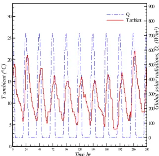
Figure 2 shows the time wise variation of the ambient temperature and total solar radiations received by south faced wall, during a typical decade representing the cold period of the year (winter -January in Casablanca-Morocco, 33°36'N, 07°36'W). Data analysis shows the minimum temperatures are obtained during the night. On average, temperatures minima and maxima range between 5°C and 18°C, respectively, and the ambient temperature swing between these extremes. Radiations remain zero during the night and increase in the following day. Solar radiations, Qext, received by a south oriented vertical
wall are zero during the first 6 hours every day and increases with the sunrise and the ambient temperature increases. Solar radiation reaches a maximum value (720 W/m²) between solar noon and 15h00 and falls to 0 W/m² at 18h00 (sunset and cancellation of solar radiations). Radiations remain zero during the night. Casablanca climate is characterized by significant temperature fluctuations with lower nocturnal values of temperature.
Figure 3 compares the thermal behavior of the ordinary wall and the composite wall with PCM, (Tm=16
°C -Table 1). Data analysis shows that the inside wall temperature increases from 16°C to 25°C for wall/PCM and from 14 °C to 34 °C for an ordinary concrete wall without PCM. Remember that ambient temperature varies between 5°C to 15°C (Figure 2), but the wall receives also a heat flux due to the solar radiations absorbed by the concrete ( =0.8) combined with convective heat flux that increases the PCM temperature to the melting point (Tm= 16°C). Also, remark that sensible heat storage stops and
latent heat process starts (Figure 4). As a result, a first layer of the liquid phase appears (f > 0) and the latent heat storage develops with the start up of the melting process. For the PCM wall case, the slop of T curve weakens during the phase change because the melting and solidification occur at a constant temperature. The increase of solar radiations accumulates sensible heat storage in concrete and latent heat in PCM layer. The composite PCM-Concrete wall can be considered as an important heat storage device. The excess of heat is stored in the wall with less temperature fluctuation until the full melting of PCM (f=1). The stored heat during a day is used for heating needs in the following night. Figure 3 shows also that PCM is totally melted at 11h00 (f=1) and the sensible heating continue and leads to the increase of wall face temperature between 11h00 and 17h00. This result is confirmed by Figure 4 which gives the latent, qL, and sensible heat, qs, variations. Analysis of such figure shows that, qL, is more important than,
qs, and remains constant between 11h00 and 17h00 (f =1). The overheating of melted PCM layer is due
21h00 and the inner wall temperature falls after a certain delay due to the thermal inertia and to the weak value of its thermal conductivity. Note that minimum temperature reached in case of the wall with PCM is clearly greater than that achieved without PCM because the heat lost by the wall is shifted by the release of the important stored latent heat. Figure 4 shows, also, that PCM solidify and melts periodically and the stored latent heat, qL, varies between 18.5MJ and 43MJ. Day/night cycles allow for
charging/discharging of the PCM and wall temperature varies from 16°C to 25°C. The fluctuation intensity of the inner temperature (concrete with PCM case) decreases with the development of the latent heat of fusion. The accumulated heat during the melting processes added to the sensible overheating of the liquid PCM, qs increases, lead to the enhancement of the inner temperature during the night. The
latent heat stored in the wall/PCM shifts the fast decrease of the temperature during the night and the inside temperature of the PCM concrete wall is less fluctuating. Note that for wall without PCM sensible heat qs decreases to negative values at night that explains the lower values of temperatures reached in
case of ordinary wall.
0 24 48 72 96 120 144 168 192 216 240
0 100 200 300 400 500 600 700 800 900 0 5 10 15 20 25 30 Q Tambient T am bien t (° C ) Gl ob al sol a r rad ia ti ons, Q , (W/ m² ) Time, hr
Figure 2. Time wise variations of the ambient temperature, Ta, and the global solar radiations, Qext,
received by a south oriented vertical wall, (January- Casablanca, Morocco 33°36'N, 07°36'W)
0 12 24 36 48 60 72 84 96 108 120 132 144 156 168 180 192 204 216 228 240 5 10 15 20 25 30 35 40 0.1 0.2 0.3 0.4 0.5 0.6 0.7 0.8 0.9 1 T NoPCM TWithPCM f Li qu id e fra ct io n , f Inne r wa ll te m p er at u re, T (° C ) Time, hr
0 24 48 72 96 120 144 168 192 216 240 0.0 5.0 10.0 15.0 20.0 25.0 30.0 35.0 40.0 45.0 50.0 -1.0 0.0 1.0 2.0 3.0 4.0 5.0 6.0 7.0 8.0 9.0 10.0 qL qs withPCM qs NoPCM Time, hr s q (MJ ) L q (M J)
Figure 4. Variations of the latent heat, qL, and sensible heat, qs
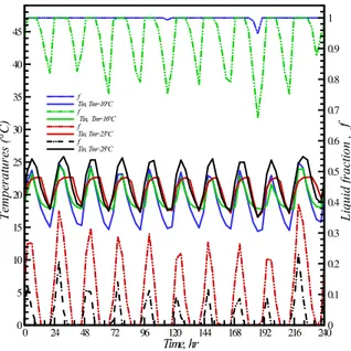
In order to investigate the effect of the PCM melting temperature on its thermal performance, a study was made by modifying the parameter , Tm, then examining the effect on, T1,in, qL, qs and temperature
fluctuations. Figure 5 sketches the time wise variation of the concrete/PCM wall temperature for various melting temperature of the PCM layer: Values tested range within the interval less than, near and greater than the comfort temperature, Tc=22°C. The liquid fraction, f, is also presented. Data analysis shows that
the inner temperature relative deviations max min c
T T
T
−
are 0.53 , 0.19, 0.22 and 0.43 for melting temperature
Tm equals to 10°C , 16 °C , 23 °C and 28 °C , respectively. So it’s clear that when the melting
temperature of the PCM layer is close to the comfort value, Tc=22°C, better are the living thermal
conditions with less temperature fluctuations. For Tm equals to 10°C, PCM completely melts (f =1) and
never solidifies and, so, latent heat is disabled. The same behavior was found when Tm equals to 28°C
The PCM remains in solid state and a weak quantity of PCM is melted , f < 0.1, and latent heat doesn’t work. In contrast when setting Tm near to the thermal comfort value 22°C an important amount of the
PCM is discharged and solidified (f=0) at night and during the following day as a result good nocturnal heating of the wall and important diurnal melting of the PCM.
0 24 48 72 96 120 144 168 192 216 2400 0.1 0.2 0.3 0.4 0.5 0.6 0.7 0.8 0.9 1 0 5 10 15 20 25 30 35 40 45 f Tin, Tm=10°C f Tin, Tm=16°C f Tin, Tm=23°C f Tin, Tm=28°C f T em p er a tu re s (° C ) L iq u id fr a ctio n , Time, hr
The performance of the wall with PCM as a heating system for the building has been evaluated in terms of Thermal Load Leveling, TLL, and daily (24 hours) heating potential, Qh, using the following equation
[8]:
( ) ( )
( )
i, ini, in maxmax( )
i, ini, in minmin 24h p 1,in a t=1
T - T
TLL =
T + T
Q = c ( T (t) - T (t) )
⎧ ⎪ ⎪ ⎨ ⎪
⎪⎩
∑
(13)
Thermal load leveling, TLL, puts a figure on the fluctuations of temperature inside the room. The less the fluctuations the better is the environment for the occupants. In winter, without heating arrangement for thermal comfort requirements,thermal load leveling should have lower value by incorporating heating method due to the increase of
( )
Ti, in max+ T( )
i, in min) and the decrease of (( ) ( )
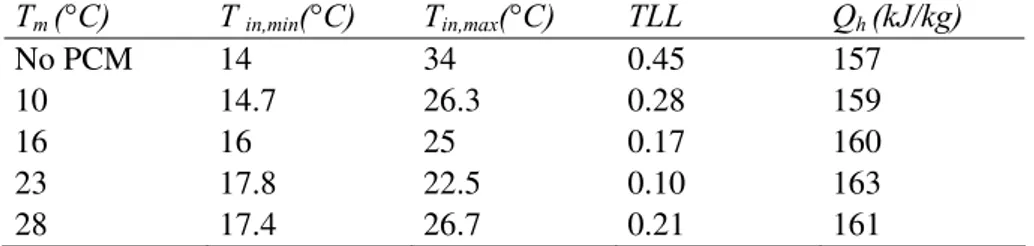
Ti, in max- Ti, in min).The results for daily variation of thermal load leveling for wall with and without PCM are summarized in Table 2. It can be seen that the value of TLL is maximum for the wall without PCM and it is reduced to about 20 % for composite wall with PCM with accurate melting temperature. The lower values of thermal load leveling indicate the decrease in the fluctuations of inner face and, thereby, there occurs an improvement of thermal comfort environment in the building. Also, the daily variations of total heating potential Qh obtained from PCM wall for typical cold days were calculated and have been accumulated in
Table 2. From the results, it is found that the heating potentials obtained in case with PCM wall were higher as compared to an ordinary wall.
Table 2. Thermal load leveling
Tm (°C) T in,min(°C) Tin,max(°C) TLL Qh (kJ/kg)
No PCM 14 34 0.45 157
10 14.7 26.3 0.28 159
16 16 25 0.17 160
23 17.8 22.5 0.10 163 28 17.4 26.7 0.21 161
4. Conclusion
A numerical investigation of the thermal performance of sandwiched concrete/PCM wall was performed. The results showed a significant reduction of indoor wall temperature due to absorption of solar gains in the composite wall in conjunction with melting of the PCM. It can therefore be concluded that PCM is effective for storage of solar gains and improvement of thermal comfort. Additional numerical simulations using different melting temperatures to control the inside temperature of the wall were conducted. The results showed that the wall thermal load leveling of the wall containing PCM with melting point near thermal comfort temperature was reduced about 25% compared to the wall without PCM with lower peak temperatures and more constant conditions, smoothing out the daily temperature fluctuations. This demonstrates the significant contribution and potential of the use of PCM in building envelopes for energy savings and thermal comfort.
Nomenclature
cp specific heat, (kJ/kg K) Indices
f liquid fraction i Interface
em PCM layer thickness, (m) m melting, PCM
h enthalpy, (J) c Comfort
hi inner wall convective heat transfer coefficient, (W/m2 K) sky Sky
ho outside wall convective heat transfer coefficient, (W/m
2
K) in inner wall face
r sky
h irradiative heat transfer coefficient, (W/m2 K) out outer wall face
k thermal conductivity, (W/m K) +,- right, left nodes
qL latent heat stored per square meter of the wall, (J) Greeks
qS sensible heat stored per square meter of the wall , (J) ρ density, (kg/m3)
Qext solar radiation, (W/m2) ABSORPTIVITY
Qw,rad heat lost to the ambient by radiations, (J) α thermal diffusivity, (m/s²)
x Cartesian coordinate, (m) σ Stefan Boltzmann constant
t time, (s) ε concrete emissivity
T temperature, (°C) latent heat of PCM (kJ/kg)
References
[1] Zalba, B., Marın, J.M., Cabeza, L.F., Mehling, H., 2003. Review on thermal energy storage with phase change: materials, heat transfer analysis and applications. Applied Thermal Engineering 23 (3), 251e283.
[2] A. Castell, I. Martorell, M. Medrano, G. Pe rez, L.F. Cabeza, Experimental study of using PCM in brick constructive solutions for passive cooling, Energy and Buildings 42 (2010) 534–540.
[3] Koschenz, M., Lehmann, B., 2004. Development of a thermally activated ceiling panel with PCM for application in lightweight and retrofitted buildings. Energy and Buildings 36 (6), 567e578. [4] Esam M. Alawadhi , Hashem J. Alqallaf, Building roof with conical holes containing PCM to
reduce the cooling load: Numerical study, Energy Conversion and Management 52 (2011) 2958– 2964.
[5] F. Agyenim, N. Hewitt, The development of a finned phase change material (PCM) storage system to take advantage of off-peak electricity tariff for improvement in cost of heat pump operation, Energy and Buildings 42 (2010) 1552–1560.
[6] X. Fang, Z. Zhang, A novel montmorillonite-based composite phase change material and its applications in thermal storage building materials, Energy and Buildings 38 (2006) 377–380. [7] V. Butala, U. Stritih, Experimental investigation of PCM cold storage, Energy and Buildings 41
(2009) 354–359.
[8] F. Berroug, E.K. Lakhal, M. El Omari, M. Faraji, H. El Qarnia, Thermal performance of a greenhouse with a phase change material north wall, Energy and Buildings 43 3027–3035 (2011). [9] V.R. Voller and S.PENG An enthalpy formulation based on an arbitrarily mesh for solution of the
stefan problem. Computational Mechanics, 14:492-502, 1994.
[10] W.C. Swinbank, Long-Wave radiation from clearskies, Quarterly Journal of the Royal Meteorological Society 381(89) 339-348, (1963).
[11] Patankar, S.V., Numerical Heat Transfer and Fluid Flow, Hemisphere, 1983.
Mustapha Faraji received the engineer degree in industrial process from National School of Mineral Industry (ENIM), Rebat- Morocco, in 1995. In 2010, he obtained Ph.D degree in thermal and fluids mechanic from Cadi Ayyad University- Faculty of Science Semlallia- Morocco. In 1996, he joined the Technological Institute, IFT Marrakesh. He is currently Professor at the Hassan II University-Physics Department, LPMMAT Laboratory in Faculty of Sciences- Ain Chock- Casablanca- Morocco. His research interests are in the area of Energy efficiency, heat transfer; in particular, heat exchanger, heat storage, liquid-solid phase change process and their applications for the thermal comfort in buildings and in thermal control electronic components, and Nano heat transfer.

![Table 1. Thermophysical properties [1]](https://thumb-eu.123doks.com/thumbv2/123dok_br/17096762.237145/4.892.265.629.347.548/table-thermophysical-properties.webp)