Article
Printed in Brazil - ©2013 Sociedade Brasileira de Química0103 - 5053 $6.00+0.00A
*e-mail: [email protected]
A Microflow Analyzer with an Integrated Gas Diffusion Unit
Alexandre Fonseca* and Janaína da C. B. Silva
Instituto de Química, Universidade de Brasília, CP 4478, 70910-900 Brasília-DF, Brazil
Este trabalho descreve o desenvolvimento de um micro-analisador de fluxo com unidade de difusão gasosa integrada. A fotolitografia profunda no ultravioleta foi empregada para gravar os canais (largura de 500 µm e profundidade de 440 µm) sobre duas placas de fotoresiste de uretana-acrilato (UA), e uma membrana de politetrafluoretileno (PTFE) foi adaptada entre as estruturas planejadas para a manipulação das soluções doadora e aceptora. Para a realização de medidas de condutividade, três pares de eletrodos (seis fios de cobre com 0,5 mm de diâmetro) foram acoplados ao sistema, através de canais-guia, ortogonais ao canal de detecção. O dispositivo microfluídico proposto apresentou um volume interno total de 48 µL e suportou vazões de até 1,0 mL min−1 sem vazamentos ou rompimento da membrana. Os sinais analíticos para a
determinação de bicarbonato em águas minerais proporcionaram uma resposta linear (R2 = 0,999)
para a faixa de concentração estudada (20 a 80 mg L−1), um limite de detecção (LOD) de 2,3 mg L−1
e desvio padrão relativo (RSD) de 2,5% (n = 5). Um desempenho similar foi observado para a determinação de amônio em pastilhas medicinais (R2 = 0,998 (10-40 mg L−1), LOD = 2,9 mg L−1
e RSD = 3,0% (n = 5)). As freqüências de amostragem para os procedimentos com HCO3− e
NH4+ foram 15 e 25 injeções h−1, respectivamente. Para ambas as aplicações, os resultados foram
concordantes com aqueles obtidos por titulações potenciométricas (HCO3−) e espectrofotometria
UV-Vis em batelada (NH4+). Adicionalmente, utilizando-se vazões de 40 µL min−1 para as soluções
aceptora e doadora, uma redução de aproximadamente 75% na geração de resíduos foi calculada ao se comparar o micro-analisador com um sistema de análise em fluxo convencional. Estes resultados demonstraram a viabilidade de se desenvolver micro-analisadores de fluxo com unidade de difusão gasosa e detecção condutométrica.
This work describes the development of a microflow analyzer with an integrated gas-diffusion unit. Deep ultraviolet photolithography was employed to engrave the channels (width of 500 µm and depth of 440 µm) on two plates of urethane-acrylate (UA) photoresist, and a polytetrafluoroethylene (PTFE) membrane was adapted between the structures designed for manipulation of donor and acceptor solutions. To perform the conductivity measurements, three pairs of electrodes (six copper wires with 0.5 mm diameter) were coupled into guiding channels, orthogonal to detection channel. The proposed microfluidic device presented a total internal volume of 48 µL and supported flow rates up to 1.0 mL min−1 without leakages or membrane damages. Analytical signals for the
determination of bicarbonate in mineral waters provided a linear response (R2 = 0.999) for the
concentration range studied (20 to 80 mg L−1), a limit of detection (LOD) of 2.3 mg L−1 and a
relative standard deviation (RSD) of 2.5% (n = 5). A similarperformance was observed for the determination of ammonium in medicinal tablets (R2 = 0,998 (10-40 mg L−1), LOD = 2.9 mg L-1
and RSD = 3.0% (n = 5)). The sampling rates for HCO3− and NH4+ procedures were 15 and
25 injections h−1, respectively. For both applications, results agreed with those obtained by
potentiometric titrations (HCO3−) and UV-Vis spectrophotometry (NH4+). In addition, by using a
flow rate of only 40 µL min−1 for donor and acceptor solutions, a reduction of approximately 75%
in residues generation was estimated by comparing the micro-analyzer with a conventional flow analysis system. These results demonstrate the viability of developing microflow analyzers with anintegrated gas diffusion unit and conductometric detection.
Introduction
Membrane separation is a simple and effective
procedure used to transfer target compounds from complex matrixes (donor phase) to another phase (acceptor) free from interferences.1,2 Porous or non-porous membranes
of different materials have been extensively used in separation processes such as gas diffusion,3 dialysis4
and pervaporation,5 which can be applied as sample
pre-treatment for the determination of organic or inorganic species in a great variety of samples. The easy manipulation, cleaning, automation and low cost also corroborate to the success of this separation strategy in many methods of analysis.
For analytical purposes, membrane-based separations are frequently performed using flow procedures1,2,6 as
flow injection analysis (FIA) and/or sequential injection analysis (SIA). In these approaches, a planar thin film7
or a holow-tube membrane3 is used as a barrier between
the donor and the acceptor streams in a separation unit (Separator) thoroughly designed for this application. By using the adequate flow manipulation as stopped flow and/or recirculation2 of the solutions along the separator, the
efficiency of the process can be improved. Furthermore, the fine control of the volumes and flow rates of the working solutions contributes to the good reproducibility.
In order to improve the flow analysis performance in terms of reagent/sample consumption, residue generation and portability, micro-fluidic devices have been developed for analytical determinations. Many researchers report the construction of flow microananalyzers in polymers,8
glass9 and ceramic,10 using different microfabrication
techniques and the successful application of the proposed devices. However, the integration of physical units for on-line sample pre-treatment as columns filled with solid material and membrane-based separators is still a challenge in microfluidics, because the microfabrication techniques tend to restrict morethe use of other materials than those used to obtain the main structure of the micro-analyzer. In fact, the number of works reporting the development of microdevices with integrated units for on-line sample preparation is still limited.
Considering these aspects, recent studies have been
developed for the integration of membrane separator
units in microfluidic devices. Shameli et al.11 described
the construction of a Quartz/SU-8 chip integrated with polydimethylsiloxane (PDMS) membranes used to separate the electrolytes in the reservoirs from the sample channels required for electrophoretic separation of proteins. Special effort to sealing the hybrid microfluidic structure was necessary to avoid leakages, even under low pressures.
Kaufman et al.12 reportedthe development of a microfluidic
separator constructed with two poly-methyl-methacrylate (PMMA) machined plates and a PDMS membrane. They demonstrated the possibility of using the microfluidic technology to perform high pressure separation procedures as reverse osmosis (RO) and nano filtrations (NF). In the studies proposed by Nge et al.,13 a negatively charged
ion-permeable membrane was directly photopolymerized in a punctual area of a microchannel (PMMA microfabricated) and used to separate proteins based on both size and charge of the molecules.
At this point, it is also important to highlight the need forsimple and low cost techniques to fabricate microfluidic devices. Recently, Fonseca et al.14,15 proposed the use of
a deep ultraviolet (UV) photolithographic process16 for
rapid prototyping of microflow injection analyzers (µFIA) with fluorimetric or fotometric integrated detection. The micro-analyzers were successfully applied to the determination of Ca2+, Mg2+, Cr(VI) or Cl− in waters and
proved to be a good alternative to perform the miniaturization of wet analytical procedures. However, the proposed devices lack units for sample preparation based on membranes and/or packed columns, which could expand their analytical applications.
In the present work, the photolithographic procedure employed by Fonseca et al.14 was used to develop a microflow
analyzer with anintegrated gas diffusion unit. The rapid adaptation of a polytetrafluoroethylene (PTFE) film between two blocks of urethane acrylate (UA) containing donor and acceptor channels as well as a conductometric cell wasdescribed. The performance of the proposed device is discussed for the determination of bicarbonate ions in mineral waters and for the determination of ammonium ions in medicinal tablets used to treatsore throat pain.
Experimental
Apparatus
A lab-made photo-exposer machine equipped with two UV lamps (Philips Actinic-BL, TL-D 15W, 380 nm) was constructed and used to perform the resist polymerization. Photomasks were designed using the AutoCad-2002 software (AutoDesk) and printed on an overhead transparency at a resolution of 1200 dpi with a laser printer (HP LaserJet P2055dn). An ultrasonic bath (Unique-Ultracleaner 1400) was employed for the development of the photolithographed structures.
Aperistaltic pump (Ismatec-Reglo Analog) equipped with TygonTM tubes (0.19 and 0.38 mm internal diameters)
(NResearch-225T031) were employed to control flow directions. Software to control all the operations of the micro-analyzer and for data acquisition through a USB interface (USB-6009, National Instruments) was written in Microsoft VisualBasic 6.0.
Conductivity measurements were performed usinga digital conductivity meter (Cole Parmer Instruments model 19101-10) equipped with lab-made copper electrodes (0.5 mm diameter wires) adapted to the integrated flow cell of the micro-analyzer.
In order to compare and validatethe results obtained fromµFIA, a pHmeter (Hanna-pH 21) with glass electrode was used to perform potentiometric titrations of HCO3− in
mineral waters and aUV-Vis spectrometer (Agilent 8453) was employed for the determination of NH4+ in medicinal
tablets.
Reagents and solutions
Urethane-acrylate photoresist (Macdermid, trademark Flexlight G-50 LBS) was purchased from Carimbos Medeiros.17
Analytical grade reagents and distilled/deionised water were used to prepare all solutions.
For the determination of bicarbonate, reference solutions from 20.0 to 80.0 mg L−1 were prepared by
proper dilution of a 2000 mg L−1 bicarbonate stock
solution in previously boiled distilled water. Sodium Bicarbonate salt (Synth) was used to prepare the stock solution. 0.05 mol L-1 sulfuric acid, used as donor carrier
stream, was prepared by dilution of a 97% (m/m) stock solution (Vetec). Commercial mineral waters were acquired in the local market and appropriately diluted with previously boiled distilled water.
For the determination of ammonium, a 1000 mg L−1
stock solution was prepared by dissolving the appropriate amount of ammonium chloride (Synth) in distilled water. Reference ammonium solutions, ranging from 10.0 to 40.0 mg L−1, were prepared by proper dilution of the stock
solution. 0.2 mol L-1 NaOH, used as donor carrier stream,
was prepared by dissolving the appropriate amount of the basis (Synth) in water. Tablets indicated for sore throat pain from three different manufacturers were dissolved in water and appropriately diluted before measurements.
8.0 mmol L-1 hydrochloric acid solution was prepared
by proper dilution of a 37% (m/m) reagent (Synth) and standardized with dry sodium carbonate before titration of mineral waters. Nessler reagent solution for the spectrophotometric determination of NH4+ in medicinal
tablets was prepared as previously described18 using KI
(Cromoline), HgCl2 (Vetec) and NaOH (Synth).
Fabrication of the micro-analyzer
The proposed micro-analyzer was manufactured by using a photolithographic process previously described.14
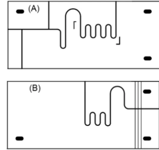
Two independent masks were printed ontransparency films and used to engrave the structures for manipulation of donor and acceptor solutions, respectively (Figure 1). The donor structure comprises the channels for hydrodynamic injection19 and a coil wherethe membrane film used for gas
diffusion separation is placed. The other structure contains the acceptor coil, which closely fits to the donor coil, and six channels to attach three pairs of electrodes used for conductometric measurements.
After the photolithographic process, a 1.0 cm × 2.0 cm PTFE membrane (0.45 µm pore size, PTFE Filter-Sartorius Biolab) was manually placed between the donor and the acceptor structures, covering the area defined for the separator coils. The “sandwich” containing both structures and the membrane was then exposed to UV irradiation in order to seal the microfluidic device. As previously described,14 by controlling the exposure times of the
photoresist, the surfaces of donor and acceptor structures presented a thin layer of non-polymerized resist, which acts as an adhesive and allows the irreversible union of the structures.
To access the micro-analyzer, hypodermic needles (305111-BDTM) with external diameters of 0.45 mm were
coupled to channels previously engraved in the polymeric substrate. In a similar way, the electrodes for conductance measurements were inserted into guiding channels perpendicular to a flow channel of the acceptor structure. The distance between the extremities of the electrodes was approximately 500 µm (the width of the flow channel used as conductivity cell).
Procedures
The flow diagram depicted in Figure 2(A) was used to perform the bicarbonate and ammonium determinations. Reference and sample solutions were introduced into the device by means of hydrodynamic injection.9 By turning
on all solenoid valves (V1-V4), the 2.5 µL sampling loop was filled with the solution. When all valves were turned off, sample plug was propelled to the gas diffusion unit in the carrier stream (basic solution for ammonium and acid solution for bicarbonate) and the gas product (CO2/NH3) permeated the membrane, being collected by the acceptor stream (distilled water). Changes in the acceptor solution conductivity were measured with the integrated electrodes and related to the concentrations of sample or reference solutions.
Results and Discussion
Micro-analyzer characterization
A membrane made with the same material used to construct the micro-analyzer was first evaluated to perform
gas diffusion separations in a µFIA. By using a glass slide, the UA photoresist was manually spread over a PMMA plate and the thickness of the film (approximately 0.2 mm) was defined by insulating tapes (limiters) previously fixed at the flat surface of the support. After UV exposition, the cured membrane was washed, dried and integrated to the micro-analyzer between the acceptor and donor structures in a similar way used to adapt the PTFE membrane. Although this membrane has been perfectly integrated into the system, with no apparent leakages or clogging of the channels, it did not provide a good performance for gas diffusion. Preliminary assays carried out in a conventional FIA system with the proposed UA membrane demonstrated low separation efficiencies, because no analytical signal was detected even for solutions with high concentration of the analyte. As indicated in Figure 3, the proposed membrane has a non-porous structure, which is unsuitable for gas diffusion separations2 and, for this reason, it has not
been applied for the determinations reported in this work.
After these preliminary studies, the integration of a PTFE membrane was evaluated. The hydrophobicity and porosity of films made with this material allowed an efficient separation of gaseous substances, providing an easy and rapid way to isolate target compounds from complex matrixes.1,2 The wide use of PTFE membranes in
flow analysis separators also contributed for the selection of this material in the present work.
Figure 2(B) shows a photograph of the proposed micro-analyzer with PTFE membrane indicating the sampling loop (SL), the gas diffusion unit (GDU) and the conductometric flow cell (CFC). All components were integrated in a 7 cm × 3 cm × 0.4 cm UA monolith, occupying an area smaller than a credit card.
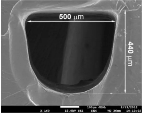
As shown in Figure 4, photolytographed channels presented “U-shaped” cross sections. Due to theuse of a
Figure 2. FIA manifold forthe determination of bicarbonate in mineral waters and ammonium in medicinal tablets (A) and photograph of the proposed micro-analyzer (B). Peristaltic pump (PP) with flow rates indicated in µL min−1, solenoid valves (V1-V4, turned-off), sampling loop (SL) defined by the AB segment (2.5 µL), gas diffusion unit (GDU), copper electrodes (E), electrode connectors (EC), conductivity meter (CDV), donor solution (DS), acceptor solution (AS), reference or sample solutions (RS), waste (W), gas diffusion unit (GDU) with PTFE membrane and conductometric flow cell (CFC) without electrodes.
lab-made photoexposer machine in the photolythographic process, channels did not present the triangular cross sections reported by Fonseca et al.14 However, it did not
constitute any limitation for the use of the device. Based on the dimensions of the channel depicted in Figure 4 (width = 500 µm and depth = 440 µm), the volumes of specific regions and the total microsystem were estimated and listed in Table 1.
By propelling distilled water through the proposed microfluidic device at a flow rate of approximately 100 µL min−1, it was observed the detachment of the PTFE
membrane in the GDU. As expected, PTFE did not bind to the UA surfaces of the donor and acceptor structures, making it impractical to carry out the separations. In order to overcome this constraint, two plates of PMMA (3.0 cm × 3.0 cm × 0.2 cm) were externally adapted above and under the GDU region, respectively, and used to press the UA structures against the PTFE with the aid of binder clips. By employing this strategy, no leakage was observed in the GDU area and solutions could be pumped at flow rates up to 1.0 mL min−1
.
It should be reported that the construction of a new miniaturized system is necessary if any damage is detected on membrane during its use. Sincethe cost to construct a new device is fairly low (ca. US$ 5.00), the proposed chip could be used as a disposable device that performs a limited
number of determinations. In fact, more than 200 injections were performed using a single device and no significant alteration was observed in analytical signals, enabling the analysis of at least 60 triplicates of samples or standard solutions. As the PTFE membranes used in this work present a controlled pore size and thickness (attested by the manufacturer) and the reproducibility for manufacturing different devices is about 10%, similar microsystems could be manufactured and used to replace the damaged ones.
The electrodes used for conductance measurements were successfully integrated to the microfluidic device. The guiding channels used for insertion of the copper wires provide the correct alignment of the electrode surfaces. In addition, due to elastomeric characteristic of the polymerized UA photoresist, the electrodes properly fitted the guiding channels, avoiding leakages during operations. Three pairs of electrodes were used in the detection cell, instead of one pair, to increase the contact area with the solutions, enhancing the sensitivity and minimizing variations in the analytical response caused by microbubbles, eventually present in flow stream.
Determination of bicarbonate and ammonium
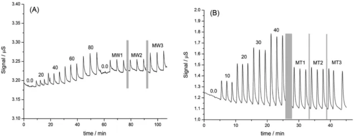
The fiagram obtained for the determination of
bicarbonate ions in mineral waters is shown in Figure 5(A). A drift of approximately 30 nS h−1 was observed and was
probably related to the small area of the electrodes, which could retain micro-bubbles or ultra-fine particulates in the acceptor solution, causing alterations in the analytical signal. Nevertheless, this drift is quite low and did not interfere in bicarbonate quantification, because good signal-to-noise ratios (greater than 15) were observed for all injections.
The analytical signals based on peak height presented a linear response (R2 = 0.999) in the concentration
range studied (signal = 0.0014 + 0.0007 [bicarbonate]), providing a limit of detection of 2.3 mg L−1 (module of
linear coefficient in the linear regression (|b| = 0.0014) plus three standard deviations obtained for the least square regression fit (3 × SD = 1.6 × 10⁻³)) and asampling rate of
15 samples h−1, using a flow rate of 40 µL min−1 both for
donor and acceptor solutions.
A relative standard deviation of 2.3% (n = 5) was calculated for sequential injections of the 80 mg L−1
reference solution, indicating a good reproducibility of the procedures. Besides, only 20 mL of residues were produced after the injection of 50 solutions. This volume represents ¼ of the residue volume generated by a conventional flow analyzer,20 so that the proposed micro-analyzer is a potential
alternative for this determination.
Table 1. Dimensions of the proposed microfluidic device
Length / mm Volume / µL
Sampling loop (SL) 13 2.5
Gas diffusion unit (GDU)a 100 19
Conductivity flow cell (CFC) 3 0.6
Entire device 250 48
aSum of donor and acceptor structures.
Table 2 lists the results for the quantification of bicarbonate ions in three commercial mineral waters. No significant differences (95% confidence level) were observed by comparing the results of µFIA with potentiometric titrations. The relative deviations, smaller than 3%, also indicate the good agreement between the results and the inexistence of systematic errors.
Figure 5(B) shows the fiagram for determination of ammonium ions performed with the micro-analyzer. The baseline demonstrated a drift of 220 nS h−1and
signal-to-noise ratios greater than 40 were measured. The analytical curve presented a linear response (R2 = 0.996)
in the concentration range studied (signal = 0.015 + 0.017 [ammonium]). Because ammonia presents higher solubility in water (541.0 g L−1 at 20 oC) than carbon dioxide
(1.7 g L−1 at 20 oC), a better sensitivity was observed for
this determination, as a result of ahigher mass transference of NH3 through the PTFE membrane.
The limit of detection of 2.9 mg L−1 (module of linear
coefficient in the linear regression (|b| = 0.015) plus three standard deviations obtained for the least square regression (3 × SD = 0.05)) was estimated for this determination. By
using the flow rate of 40 µL min−1 for donor and acceptor
solutions, approximately 25 injections could be performed in 1 h. Therefore, after 50 injections, only 10 mL of residues are generated, which also demonstrates a significant reduction in reagent consumption. The reproducibility of the procedures was 3.0% (n = 5) based on the relative standard deviation for successive injections of 40 mg L−1
reference solution.
Results for thedetermination of ammonium in medicinal tablets are listed in Table 2. Considering the concentrations determined by using the proposed µFIA and the reference method (batch spectrophotometry), a significant difference (−22.2%) was observed only for the sample MT2. In fact, differences below 5.0% were calculated by comparing all the µFIA results with the concentrations reported in the medicine labels.
Although the concentrations described by the medicinal tablet manufacturer are not completely reliable, these results can indicate interferences in the reference method caused by MT2 composition, which were eliminated using the membrane separation process with µFIA. Studies performed with the diluted MT2 sample solution, prepared
Table 2. Determinations of bicarbonate in mineral waters and ammonium in medicinal tablets
Analyte Sample µFIA Reference Deviation / %
Bicarbonatea / (mg L−1)
MW1 103.3 ± 4.0 101.2 ± 0.1 +2.1
MW2 98.6 ± 6.0 100.2 ± 1.0 −1.6
MW3 69.5 ± 1.3 69.4 ± 1.7 +0.2
Ammoniumb / (mg g−1)
MT1 4.8 ± 0.1 4.90 ± 0.01 −2.0
MT2 5.4 ± 0.1 6.94 ± 0.02 −22.2
MT3 6.8 ± 0.2 7.04 ± 0.05 −3.4
Values are the average for three determinations; apotentiometric titration was used as reference method; bbatch spectrophotometry was used as reference method.
without the chromogenic reagent, provideda very low absorbance signal (near zero), indicating that the sample dye did not interfere in spectrophotometric measurements. Thus, interference may be caused by sample matrix in the colorimetric reaction.
It isalso important to consider that all samples solutions injected in microfluidic device presented considerable amounts of dye and other substances that did not interfere in the conductometric analytical results, demonstrating the adequate performance of the proposed µFIA to isolate and detect the analyte.
Conclusions
The micro-analyzer proposed in this work was rapidly constructed using a simple and low cost fabrication technique. The feasibility of online gas diffusion separations applied for real samples was properly demonstrated and indicates that this microfluidic device is auseful and an innovative tool to perform membrane-based sample pre-treatment procedures. In addition, the low consumption of reagents and reduced amount of waste generated perfectly fit the aims of green chemistry.
Acknowledgments
Authors are grateful to Instituto Nacional de Ciências e Tecnologias Analíticas Avançadas (INCTAA), Conselho Nacional de Desenvolvimento Científico e Tecnológico (CNPq - grant 573894/2008-6) and Decanato de Pesquisa e Pós-graduação of Universidade de Brasília (DPP-UnB - process 10/2011) for financial support. J. C. B. Silva acknowledges Coordenação de Aperfeiçoamento de Pessoal de Nível Superior (CAPES-REUNI) for a fellowship.
References
1. Hylton, K.; Mitra, S.; J. Chromatogr. 2007, 1152, 199. 2. Miró, M.; Frenzel W.; TrAC, Trends Anal. Chem.2004,23,
624.
3. Coelho, L. H. G.; Melchert, W. R.; Rocha, F. R.; Rocha, F. R. P.; Gutz, I. G. R.; Talanta 2010, 83, 84.
4. Suliok, M.; Miró, M.; Stingeder, G.; Koellensperger, G.; Anal. Chim. Acta 2005,546, 1.
5. Satienperakul, S.; Phongdong P.; Liawruangrath, S.; Food Chem.
2010,121, 893.
6. Melchert, W. R.; Reis B. F.; Rocha, F. R. P.; Anal. Chim. Acta
2012, 714, 8.
7. Tue-Ngeun, O.; Sandford, R. C.; Jakmunee, J.; Grudpan, K.; McKelvie, I. D.; Worsfold, P. J.; Anal. Chim. Acta2005, 554, 17.
8. Romoli, L.; Tantussi, G.; Dini, G.; Opt. Lasers Eng.2011, 49, 419.
9. Xue, N.; Yan, W.; IEEE Sens. J.2012, 12, 1914.
10. Almeida, S. A. A.; Arasa, E.; Puyol, M.; Martinez-Cisneros, C. S.; Alonso-Chamarro, J.; Montenegro, M. C. B. S. M.; Sales, M. G. F.; Biosens. Bioelectron.2011, 30,197.
11. Shameli, S. M.; Elbuken C.; Ren, C. L.; Pawliszyn, J.;
Electrophoresis 2011,32, 333.
12. Kaufman, Y.; Kasherb, R.; Lammertinkc, R. G. H.; Fregerd, V.;
J. Membr. Sci. 2012, 396, 67.
13. Nge, P. N.; Yang, W.; Pagaduan, J. V.; Wooley, A. T.;
Electrophoresis2011,32, 1133.
14. Fonseca, A.; Raimundo Jr., I. M.; Rohwedder, J. J. R.; Ferreira, L. O. S.; Anal. Chim. Acta2007, 603, 159.
15. Fonseca, A.; Raimundo Jr., I. M.; Rohwedder, J. J. R.; Araújo, M. C. U; Lima, R. S.; Anal. Bioanal. Chem. 2010, 396, 715. 16. Fernandes, J. C. B.; Ferreira, L. O. S.; J. Braz. Chem. Soc.2006,
17, 643.
17. http://www.medeiros.com.br/ accessed in July 2012
18. Jeffery, G. H.; Basset, J.; Mendham, J.; Denney, R. C.; Vogel’s Textbook of Quantitative Chemical Analysis, 5th ed.; Longman:
New York, 1989.
19. Ruzicka, J.; Hansen, E. H.; Anal. Chim. Acta1983, 145, 1. 20. Oliveira, P. C. C.; Masini, J. C.; Galhardo, C. X.; Lima, J. C. S.;
Sant’ana, A. E. G.; Vasconcelos, A. M. G.; Nunes, W. P.; Amaral, O. L. C.; J. Braz. Chem. Soc. 2006, 5, 976.