Revisão
*e-mail: [email protected]
HYDROGEN PRODUCTION BY ALKALINE WATER ELECTROLYSIS
Diogo M. F. Santos* and César A. C. Sequeira
Materials Electrochemistry Group, ICEMS, Instituto Superior Técnico, TULisbon, Av. Rovisco Pais, 1049-001 Lisboa, Portugal José L. Figueiredo
Laboratório de Catálise e Materiais (LCM), Laboratório Associado LSRE/LCM, Departamento de Engenharia Química, Faculdade de Engenharia, Universidade do Porto, R. Dr. Roberto Frias, 4200-465 Porto, Portugal
Recebido em 13/12/12; aceito em 28/5/13; publicado na web em 17/7/13
Water electrolysis is one of the simplest methods used for hydrogen production. It has the advantage of being able to produce hydrogen using only renewable energy. To expand the use of water electrolysis, it is mandatory to reduce energy consumption, cost, and maintenance of current electrolyzers, and, on the other hand, to increase their efficiency, durability, and safety. In this study, modern technologies for hydrogen production by water electrolysis have been investigated. In this article, the electrochemical fundamentals of alkaline water electrolysis are explained and the main process constraints (e.g., electrical, reaction, and transport) are analyzed. The historical background of water electrolysis is described, different technologies are compared, and main research needs for the development of water electrolysis technologies are discussed.
Keywords: alkaline water electrolysis; cell components; hydrogen production.
INTRODUCTION
Hydrogen, as an energy carrier, has become increasingly important, mainly in the last two decades. It owes its popularity to the increase in the energy costs caused by the uncertainty in the future availability of oil reserves1 and also to the concerns about global warming and climate changes, which are blamed on manmade carbon dioxide emissions associated with fossil fuel use,2 particularly coal.3 Hence, despite the cost of hydrogen being still higher than most fossil fuels, its unique set of properties is finding new applications in many directions: hydrogen--fuelled forklifts are being used in enclosed spaces, different types of fuel cells (FCs) are being used in power production, major cities have implemented hydrogen-fuelled buses, FCs for electronic devices and mobile phones are close to commercialization; Germany is manufac-turing and selling hydrogen-fuelled submarines, some companies are experimenting on hydrogen-fuelled sea-going vessels, and hydrogen FCs are being considered in aerospace applications.4
Today, these major changes in our society have led hydrogen pro-ducers and some petroleum companies to establish hydrogen-fuelling stations throughout Japan and Germany. Major car companies are planning to start selling hydrogen-fuelled cars in Germany, Japan, and those places where there are enough hydrogen-fuelling stations, in 2–3 years’ time.4 Clearly, hydrogen has been perceived as a valid alternative to fossil fuels in many applications because of its advantage of being a clean fuel, considering that its use emits almost nothing other than water. Additionally, it can be produced using any energy source, with re-newable energy being most attractive,5 making it one of the solutions to sustainable energy supply in the so-called new “hydrogen economy.”6,7 Notwithstanding the increasing interest in hydrogen as an energy carrier, its main uses continue to be in petroleum refining, ammo-nia production, metal refining, and electronics fabrication, with an average worldwide consumption of about 40 million tonnes.8–13 This large-scale hydrogen consumption consequently requires large-scale hydrogen production. Presently, the technologies that dominate hydro-gen production include reforming of natural gas,14 gasification of coal and petroleum coke,15,16 as well as gasification and reforming of
heavy oil.17,18Although water electrolysis has been known for around 200 years,19,20 it still contributes only a minor fraction of the total hydrogen production (4% of the worldwide hydrogen production).21,22 When compared to other available methods, water electrolysis has the advantage of producing extremely pure hydrogen (>99.9%), ideal for some high value-added processes such as manufacture of electronic components.13 Water electrolysis is often limited to small--scale applications and to particular cases where largesmall--scale hydrogen production plants are not accessible or economical to use. These include marine, rocket, spacecraft, electronic, and food industries, as well as medical applications.
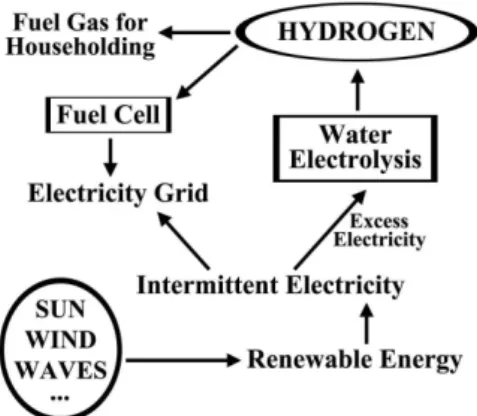
Water electrolysis works well at a small scale, and the process is even more sustainable if electricity used is derived from renewable sources (e.g., wind, solar, hydro, etc.). In a conceptual energy system involving production, conversion, storage, and use in remote commu-nities, water electrolysis may play an important role. When abundant renewable energy is available, extra energy may be stored in the form of hydrogen using water electrolysis. The stored hydrogen can then be used in FCs to generate electricity or used as a fuel gas for heating applications. Therefore, electricity generated by the renewable energy is either directly merged into the grid or used to produce hydrogen. Figure 1 illustrates such an energy system.
Remote areas with abundant solar and/or wind resources for gene-rating electricity can take advantage of water electrolysis to produce hydrogen to meet the energy needs of household applications such as lighting and heating,23 for powering telecommunication stations,24 for applications in small-scale light-manufacturing industry, for electrici-ty peak shaving, and in integrated systems, both grid connected and grid independent.25 Hydrogen produced by renewable energy sources has the advantage of mobility, which is essential for supplying energy in remote areas away from the main electricity grid.
Small-scale water electrolyzers may avoid the need for a large number of cryogenic, liquid hydrogen tanks or a huge hydrogen pipeline system. The existing electrical power grid can be used as the backbone of the hydrogen infrastructure system, contributing to the load leveling by changing operational current density in accordance with the change in electricity demand.26 Small-scale water electrolyzers may be used to produce pure hydrogen and oxygen for diverse applications, such as use of hydrogen gas in laboratories and oxygen in life-support systems in hospitals.27 It has been shown that for small systems, the dominant factor in determining the cost of electrolytic hydrogen is the cost of the electrolysis cells, whereas for large systems electricity cost and hydrogen value dominate the discussion.13
Although hydrogen possesses the advantages of availability, flexibility, and high purity, for its widespread applications hydrogen production using water electrolysis needs improvements in energy efficiency, safety, durability, operability, and portability, and, above all, reduction in installation and operation costs. These features open up many opportunities for research and development leading to technological advancements in water electrolysis. This paper presents the electrochemical fundamentals of water electrolysis and a theoretical basis for scientific analysis of the available electrolysis systems. The various water electrolysis techniques and a broad range of applications are analyzed. The main research needs are identified and future trends are discussed.
HISTORICAL BACKGROUND
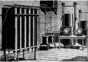
From the discovery of the phenomenon of electrolytic splitting of water into hydrogen and oxygen to the development of modern electrolyzers, water electrolysis technology has seen continuous progresses over the past 200 years.28 Following the discovery of electricity, J.R. Deiman and A.P. van Troostwijk, in 1789, used an electrostatic generator to discharge electricity through two gold wires placed inside a tube filled with water, causing evolution of gases.29 Alessandro Volta invented the voltaic pile in 1800, and a few weeks later William Nicholson and Anthony Carlisle used it for electrolytic splitting of water.30 Later, the gases produced during water electrolysis were identified to be hydrogen and oxygen. With the development of electrochemistry, the proportional relationship between electrical energy consumption and the amount of gases produced became established through Faraday’s law of electrolysis. Finally, the concept of water electrolysis was defined scientifically and acknowledged.31 With the invention of the Gramme machine in 1869 by Zénobe Gramme, water electrolysis became an economical method of producing hydrogen. A technique for industrial synthesis of hydrogen and oxygen through water electrolysis was developed later in 1888 by Dmitry Lachinov. By 1902, more than 400 industrial water electrolyzers were already in operation.30 Figure 2 illustrates such early plants used for water electrolysis.32
The period between the 1920s and the 1970s was the “golden age” for the development of water electrolysis technology,28 when most of the traditional designs were created. Driven by the industrial need for hydrogen and oxygen, the knowledge established in the first stage was applied to the industrialization of water electrolysis
technologies. In 1939, the first large water electrolysis plant, with a capacity of 10,000 N m3 H
2 h−1, went into operation, and in 1948, the first pressurized industrial electrolyzer was manufactured by Zdansky/Lonza.30 Commercial water electrolysis concepts developed in this period include most of the technological components that are currently in use.33 One of these components is the membrane. The first membranes to be commercialized were made of asbestos. However, asbestos is not very resistant to corrosion caused by a strongly alkaline environment at high temperatures. Moreover, due to its seriously adverse health effects, asbestos was gradually replaced by other materials.34 From the 1970s onward, polymers based on perfluorosulfonic acid, arylene ether, or polytetrafluoroethylene have been used as gas separation material.34,35
Configuration of the water electrolysis cell also underwent se-veral improvements through time. Typical conventional tank cells, with a unipolar configuration, are simple, reliable, and flexible. On the other hand, filter press cells, with a bipolar configuration, have lower Ohmic losses and are more compact. High-pressure water electrolyzers, which use the bipolar configuration, would be difficult to accomplish with unipolar cells. Disadvantages of the bipolar cells are related to their structural complexity, requirement of electrolyte circulation, and use of gas/electrolyte separators.36,37
The electrode material selected should have good corrosion resistance, high conductivity, high catalytic effect, and low price.38 Stainless steel and lead were pointed out as cheap electrode materials, with low overpotentials, but these cannot tolerate highly alkaline envi-ronments. Noble metals were found to be too expensive to be used as bulk electrode materials. Ni was then recognized as an electroactive cathode material with good corrosion resistance in an alkaline solution (when compared to other transition metals) and rapidly became po-pular during the development of water electrolyzers. Ni-based alloys have then started to be the object of extensive research efforts.39–41
These progresses motivated commercialization of water elec-trolyzers. The first records of commercial water electrolysis date back to 1900, when the technique was still in its early life. Two decades later, large-size electrolysis plants, rated at 100 MW, were developed in Canada, primarily to feed the ammonia fertilizer industries.42 In the late 1980s, Aswan installed 144 electrolyzers with a nominal rating of 162 MW and a hydrogen generation capacity of 32,400 m3 h−1. The Brown Boveri electrolyzer is another highly modularized unit, which is able to produce hydrogen at a rate of about 4300 m3 h−1. Stuart Cell (Canada) is a well-known unipolar tank-type cell manufacturer. Hamilton Sundstrand (USA), Proton Energy Systems (USA), Shinko Pantec (Japan), and Wellman-CJB (UK) manufacture the latest proton exchange membrane (PEM) electrolyzers.
In the first half of the 20th century, there was a huge demand for hydrogen in the production of ammonia fertilizers. This need for hydro-gen stimulated the development of water electrolysis technology, which was helped by the low cost of hydroelectricity at the time. However, then hydrocarbon energy started to be applied massively in industry. Hydrogen could be produced in large scale through coal gasification and natural gas reforming, and at much lower costs, gradually fading the economic advantage of water electrolysis. At that point, progresses on water electrolysis for hydrogen production simply ceased.
The oil crisis of the 1970s renewed the worldwide interest in water electrolysis.1 In the new hydrogen economy ideology, hydrogen was being considered to be the energy carrier of the future and the key to solve the problem of sustainable energy supply. Improving the efficiency of water electrolysis became a major goal. Novel breakthroughs were achieved at the cell level, with the emergence of PEM and pressurized water electrolyzers.43
Compact, high-pressure water electrolyzers were used to produce oxygen on board the nuclear-powered submarines, as part of the life-supporting system. The compact design eliminates the gaskets between cells, requiring high-precision machining of the cell frames. However, high operating pressures of these water electrolyzers (up to 3.5 MPa) create a major safety problem.1
In 1966, General Electric for the first time used a Nafion mem-brane to supply energy for space projects.43 The PEM discovery enabled the development of PEM water electrolysis, also named as solid polymer electrolysis (SPE), whose operation principles are basically the reverse of a PEM FC.44 Intensive studies were carried out to reduce the membrane cost.45 In the early 1970s, small-scale PEM water electrolyzers were used for space and military applica-tions. However, the short durability of the membrane makes PEM electrolyzers too expensive for general applications.44 A PEM water electrolysis system may offer greater energy efficiency, higher production rates, and more compact design than traditional alkaline water electrolysis technologies.46,47 However, special requirements are needed for several of its components (e.g., expensive polymer electrolyte membrane, porous electrodes, and current collectors), which are its serious disadvantages.25
Currently, many efforts are under way to integrate renewable energy technologies as energy sources in water electrolysis for hydrogen production, as a means for distributed energy production, storage, and use, particularly in remote communities. New water electrolysis concepts, such as photovoltaic (PV) electrolysis and steam electrolysis, are now emerging.
FUNDAMENTALS OF WATER ELECTROLYSIS
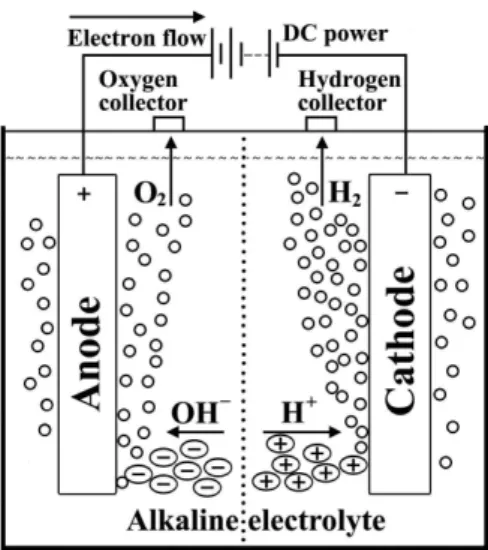
Figure 3 presents the simplest water electrolysis unit, consisting of an anode and a cathode connected through an external power supply and immersed in a conducting electrolyte. A direct current (DC) is applied to the unit; electrons flow from the negative terminal of the DC power source to the cathode, where they are consumed by hydrogen ions (protons) to form hydrogen atoms. In the general process of water electrolysis, hydrogen ions move toward the cathode, whereas hydroxide ions move toward the anode. A diaphragm is used to separate the two compartments. Gas receivers are used to collect hydrogen and oxygen gases, which are formed at the cathode and anode, respectively (Figure 3).
For the case of water electrolysis in an acid or neutral aqueous electrolyte, the processes that occur at the electrodes’ surface are described by Eqs. 1 and 2:
Cathode 2 H+
(aq) + 2 e−→ H2(g) (E0 = 0.00 V vs. SHE) (1) Anode H2O(l)→ ½ O2(g) + 2 H+(aq) + 2 e− (E0 = 1.23 V vs. SHE) (2)
The sum of these two equations leads to the overall reaction of water electrolysis, as given in Eq. 3.
Overall H2O → H2 + ½ O2 (E0 = −1.23 V vs. SHE) (3) However, for the specific case of alkaline water electrolysis, where a strong base is used as the electrolyte, the hydroxide anions are transferred through the electrolyte to the anode surface, where they lose electrons that then return to the positive terminal of the DC power source. Nickel (Ni) is a popular choice due to its low cost, good activity, and easy availability.48 To enhance conductivity, the electrolyte used in the cell should consist of high-mobility ions.49 Potassium hydroxide (KOH) is normally used in alkaline water electrolysis, thus avoiding the corrosion problems caused by acid electrolytes.42 KOH is preferred over sodium hydroxide (NaOH) because the former electrolyte solutions have higher conductivity.50 Therefore, when the process is run in an alkaline electrolyte, the electrochemical reactions occurring at the cathode and anode are given by Eq. 4 and Eq. 5, respectively:
Cathode 2 H2O + 2 e−→ H
2 + 2 OH− (E0 = −0.83 V vs. SHE) (4) Anode 2 OH−→ ½ O
2 + H2O + 2 e− (E0 = 0.40 V vs. SHE) (5) Of course the sum of Eqs. 4 and 5 will lead to the same overall reaction as described in Eq. 3, with the same value (−1.23 V) for the theoretical cell voltage. For these reactions to proceed, a number of barriers have to be overcome, which depend on the electrolysis cell components: the boundary layers at an electrode surface, electrode phase, electrolyte phase, separator, and electrical resistances of the circuit. Clearly, the performance of the electrolytic system must involve the understanding of the cell components. Therefore, it is appropriate to discuss them, at least in a relatively simple way.
Boundary layers at an electrode surface
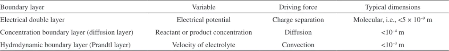
of the phenomenon resulting from the gradients and the typical extent of each boundary layer (Table 1).
The hydrodynamic and concentration boundary layers lead to mass transfer of reactants and products within the solution and will be discussed later; here the focus is on a simplified treatment of the electrical double layer resulting from the potential gradient. The electrical double layer is localized over molecular dimensions at the electrode/electrolyte interface. It arises from the charge separation between an electrode and the surrounding electrolyte. Figure 4a shows a greatly simplified model of the double layer for the case of a negati-vely charged electrode surface, i.e., one having a surplus of electrons.
The inner, or “compact,” layer consists of cations that are electrostatically held at the electrode surface and adsorbed solvent molecules. Outside of this highly structured layer lies the “diffuse” layer where the ions retain a structure that is higher in degree than that of the bulk electrolyte. The potential field resulting from this model is shown in Figure 4b. The potential decays linearly over the compact layer and then exponentially over the diffuse layer. The system behaves as two capacitances in series, one for the compact and another for the diffuse layers.
The presence of double layer has several important consequences: (i) the difference in potentials between the electrode and solution phases, φe − φs, provides the driving force for an electron transfer reaction across the interface; (ii) this driving force may be affected significantly by adsorption of species (reactants, products, solvent, ions, or contaminants) at the electrode surface; (iii) local differences in φe − φs may alter the localized driving force for reaction and hence
the rate, current efficiency, or selectivity of an electrode process; (iv) the potential difference across the interface is localized over molecular distances, causing the potential gradient to be extremely large, for example, if φe − φs is equal to 2 V, over 0.2 nm, the potential gradient will be 1010 V m−1; such a high and localized driving force enables energetically difficult processes to be carried out electrochemically; and (v) the double-layer capacitance measurements can provide useful information on adsorption at electrodes; however, it tends to create problems in kinetic studies, particularly at high-surface-area electrodes, and in case of rapid potential changes with time due to the existence of charging currents. In case of large electrodes used in industrial reactors, power supplies must be designed and controlled to handle start-up, shut-down, and other conditions where the electrode potential changes abruptly.
In the section devoted to the rate of electrode processes, kinetic expressions will be written in terms of the electrode potential, E, whi-ch is the difference between the potentials of a working electrode and a reference electrode located close to its surface in the solution. Any change in electrode potential, ∆E, can be determined from a change in potential difference across the interface, i.e., ∆E = ∆ (φe − φs).
Electrode phase
Both electrodes in a cell must have adequate mechanical strength and be resistant to erosion and other types of physical attacks by the electrolyte, reactants, and products. The physical form of the electro-des is often very important, as it must be readily accommodated within a selected reactor design to achieve sound electrical connections and can also be removed for inspection and maintenance. The shape and condition of the surface of an electrode should be designed taking into account the need for product separation such as disengagement of gases or solids. In many cases, there is a need to maintain a high surface area, a structure having turbulence-promoting properties, or a porous matrix having a reasonably low pressure drop. The active electrode material may also be a thin coating rather than the surface of a bulk material. The electrode surface has to achieve and maintain the desired reaction and, in some cases, must possess specific elec-trocatalytic properties that are essential to promote a high reaction rate for the product of interest at a low overpotential, while inhibiting all competing chemical changes. The electrical conductivity must be reasonably high throughout the electrode system, including the current feeder, electrical contacts, and the entire electrode surface, in order to avoid voltage penalties, generation of unwanted heat, as well as uneven current distribution.
Finally, the electrode performance must be obtained at a reasona-ble capital cost and maintained over an acceptareasona-ble lifetime, possibly for several years. Some of the most common electrode materials used as cathodes for the hydrogen evolution reaction (HER) are steel, stainless steel, high-area Ni on steel, and Ni and those used as anodes for the oxygen evolution reaction (OER) are Ni oxides, and Ni- and Co-based spinels, e.g., NiCo2O4 on Ti.
Electrical resistivity is a key property of electrode materials and electrode structures. For a homogeneous material with a uniform cross-sectional area A, and resistance R, over its length L, the electri-cal resistivity is defined as ρe = RA/L, with the electrical conductivity Table 1. Boundary layers at an electrode surface
Boundary layer Variable Driving force Typical dimensions
Electrical double layer Electrical potential Charge separation Molecular, i.e., <5 × 10⁻⁹ m
Concentration boundary layer (diffusion layer) Reactant or product concentration Diffusion <10−4 m
Hydrodynamic boundary layer (Prandtl layer) Velocity of electrolyte Convection <10−3 m
being the reciprocal of ρe and usually defined as k = CL/A, where the conductance, C, is the reciprocal of resistance R.
The electrical resistivity ρe determines the size of the potential drop through the electrode, which, in turn, contributes to power costs, possible heating problems, and a less uniform potential distribution. Typical ρe values for materials commonly used in electrode structures are provided in Figure 5. Only the most conducting materials, such as copper and aluminum, can be used for extensive electrical con-nections and current-carrying busbars. In the case of current feeders, high thermal conductivity is also useful in dissipating heat to the surroundings, as the electrical resistivity of most solid conductors increases with temperature. Costs and weights are also important; solid aluminum busbars (which sometimes have copper cores), copper or brass interelectrode connectors, or copper-cored flexible cables are used as appropriate. The passive film that forms on the external alu-minum surface helps avoid corrosion but can lead to high-resistance connections if precautions are not taken.
The electrode materials must preserve their physical, mechanical, and chemical stability, often over a wide range of operating condi-tions. Normal process conditions may be followed or preceded by times when the cell is overdriven at a high current density to achieve higher production or zero current conditions during periods of non--use. In some cases, the electrodes may experience electrical shorting or current reversal during switch out; they must withstand alternate current (AC) ripple in the power supply. Owing to these factors and the complexity of the surface chemistry, it is important to test electrode materials under realistic process conditions for an extended period.
There are two types of electrode processes. In one case, the electrode acts only as a source or a sink of electrons, and the reaction kinetics are expected to be independent of the electrode material. In the other case, the electrode surface acts as a catalyst, and the type and rate of reaction depend critically on specific interactions between the electrode surface and electrolyte species. In the second case, dispersed microroughened surfaces are required to be used, which provides a high and active electrode area to increase the electrocatalytic effect. It should be realized that the majority of reactions lie between these two extremes. Indeed, almost all reactions, even simple redox reac-tions and metal deposireac-tions, show a dependence on the nature of the electrode surface.
In water electrolyzers, or FCs, an electrocatalytic electrode surface is required to promote a high rate of hydrogen evolution, or hydrogen oxidation, at a low overpotential. Alkaline water elec-trolyzers often make use of high-area Ni and Ni-alloy coatings, while acid electrolyte FCs where hydrogen ionizes at the anode usually employ a dispersion of platinum (Pt) and polytetrafluoroethylene
(PTFE) on a carbon substrate. Both Ni and Pt have a high exchange current density, j0, for the H2/H+ couple and stabilize the adsorbed H through a mechanism that is closely related to catalytic hydrogenation.
Electrolyte phase
The electrolyte phase contains at least three essential components: the solvent, an inert (supporting) electrolyte (in high concentration), and the electroactive species (reactant).
A wide range of solvents are encountered in laboratory experi-ments, although factors such as cost, hazards, and recycling/disposal problems greatly limit their choice for applications in industrial elec-trochemical technology.51 The solvent should generally have the fol-lowing properties: (i) it must be liquid at the operational temperature, (ii) it must dissolve the electrolyte to provide a conducting solution, (iii) it must be chemically/electrochemically stable, and (iv) it must present fewer problems in storage or handling.
The importance of water as the most common solvent arises not only because of its low cost, inherent safety, and ease of handling, but also because of its following peculiar properties: (i) water is char-acterized by a dynamic oligomer formation via hydrogen bonding; (ii) a water molecule is small in size and has a large dipole moment, allowing it to interact electrostatically with charged species and, therefore, solvate ions readily via ion–dipole interactions; and (iii) the self-ionization of water provides a low concentration (≈10−7 mol dm−3) of protons and hydroxyl ions in a neutral aqueous solution. Moreover, water facilitates rapid acid-base equilibria by acting both as a proton donor and as a proton acceptor.
In general, for electrolysis to occur at a significant rate, it is es-sential to have a relatively high concentration of the reactant, while process economics dictate that the solvent should be stable. It is usu-ally essential for the inert electrolyte to be dissociated extensively into cations and anions. The resulting high conductivity of the solution phase has several consequences: (i) there is a relatively low solution resistance between the electrodes, avoiding extremely high cell po-tential values for a given current; (ii) anions and cations of the inert electrolyte migrate and carry the majority of the current through the electrolyte, with only a very small fraction being carried by the elec-troactive species, implying that migration is not a significant mode of mass transfer for these species, which facilitates convective–diffusion mass transfer studies; (iii) the high ionic strength of the electrolyte results in equal and constant activity coefficients for both the reactant and the product, which simplifies Nernst equation and facilitates a treatment in terms of concentrations rather than activities; and (iv) the electrical double-layer structure is simplified, as is its influence on electrode kinetics.
Our current knowledge of liquid electrolytes largely arises from the measurements of the electrolytic conductivity, κ, which is the product of conductance, C, and a calibration factor, s, known as the cell constant. Electrolytes at a typical concentration of 1 mol dm−3 have k values lying within the range of 5–25 S m−1, which is about six orders of magnitude smaller than most electrode materials.
The electrolytic conductivity, κ, is found to vary considerably with electrolyte concentration, c; the molar electrolytic conductivity, D, is defined as D = κ/c. The parameter D shows a dependence on concen-tration, and this behavior may be used to distinguish between strong (substantially dissociated) and weak (poorly dissociated) electrolytes. The fraction of charge carried by an ion is known as its transport number, denoted by the symbol t+ for a cation and t− for an anion. The transport number of cations tends to decrease slightly at higher concentrations of salts; the reverse trend is shown by H+ ions in acids.
products (as well as that of any intermediate species). For instance, taking the oxygen reduction reaction (ORR) (Eq. 6) as an example, factors leading to greater thermodynamic stability of O2 species will discourage reduction but favor oxidation.
O2 + 2 H2O + 4 e−↔ 4 OH− (6)
The formal potential for the O2/OH− couple will shift in the ne-gative direction. Also, the structural similarity of O2 and OH− species will be important. For example, the reaction kinetics will be hindered by changes in the geometry, number, or type of ligands; bond lengths; and bond angles.
Separators
An ion-permeable separator (used to separate the anode from the cathode) should be incorporated only if essential. In addition to increa-sing the cost and complexity of cell construction, a separator increases the cell resistance substantially, thereby increasing the required cell potential for a given current density. However, a separator is useful for the following reasons: (i) the anode and cathode products may be prevented from mixing in order to maintain chemical stability or safety (e.g., explosive H2/O2 gas mixtures may be avoided); (ii) to a certain extent, the anode/anolyte and cathode/catholyte choices may be made independently, e.g., the anolyte may be chosen to allow the use of an inexpensive anode or to avoid a corrosive catholyte species; (iii) prevention of parasitic redox shuttle (i.e., side reactions involving reduction of a species at the cathode followed by its reoxidation at the anode) encourages a high current efficiency for the desired reactions; (iv) selective ion transport through membranes can be an essential element of the process; and (v) the separator may prevent physical contact between the anode and cathode if the electrodes are closely spaced.
There are three main classes of separators:
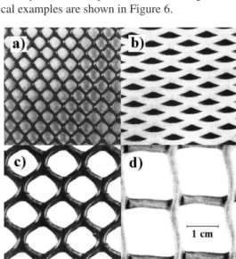
1. Porous spacers are open structures, such as plastic meshes, which provide a physical barrier between electrodes. They can offer dimensional support for fragile electrodes, a membrane, or a microporous separator. Other uses include prevention of inte-relectrode contact (hence, electrical shorting) and promotion of turbulence next to an electrode in order to enhance mass transfer. Spacers present little or no resistance to the mixing of anolyte and catholyte, and have pore sizes in the range of 0.5–12 mm. Typical examples are shown in Figure 6.
2. Microporous separators, or diaphragms, allow transport of solvent and solute, as well as ions, due to hydraulic permeability. Ho-wever, diaphragms act as both convection and diffusion barriers because of their relatively small pore sizes (0.1–50 µm). Examples include porous ceramics (e.g., asbestos, glass frits, and porous pot) and porous polymers (e.g., porous polyvinyl chloride (PVC), polyolefins, and PTFE).
3. Ion exchange membranes divide the cell into two hydraulically separated compartments; they function as barriers to convection and diffusion, while permitting selective migration of ions. The-se materials have chemically designed pores of molecular size, typically in the range of 10−9–10−8 m. Ion exchange membranes include fluorocarbon and hydrocarbon materials that have ion exchange groups distributed throughout their structure. Normally, the membrane is a thin sheet of polymer that is designed to allow passage of either anions or cations, but not both. Over the last three decades, a wide range of membranes based on perfluorinated hydrocarbon backbones have been developed (Figure 7).
The effective conductivity, keff, of a microporous or ion exchange membrane separator may be measured by determining the potential drop (i.e., iRsep, the product of the current, i, and the resistance of the separator, Rsep) across a known thickness, x, of the material while operating at a fixed current density, j; that is keff = jx/(iRsep). However, it is important to note that separators do not always show Ohmic be-havior. The effective resistivity, ρeff, of the separator is the reciprocal of keff, which, after rearranging for Rsep, gives Rsep = ρeff x/A. Separator suppliers commonly specify the “area resistance” as the product of re-sistance and area, RsepA = x/keff. Electrical resistance of the membrane is therefore minimized using a thin sheet (0.01–0.03 mm) of polymer having high ionic conductivity. Many modern membranes have an area resistance in the range of 2 × 10⁻⁵–50 × 10−5Ω m2. At a j of 103 A m−2, the potential drop across the membrane will be 0.02–0.50 V, which is often comparable to the potential drop in the catholyte or anolyte solution. The transport of species through an ion exchange membrane may be described quantitatively by a flux balance. In the case of a cation, it is given by the following expression:
(7)
where t+ and t+m are the cation transport numbers in the electrolyte and the membrane, respectively; F is the Faraday’s constant (96,485 C mol−1); k
m is the mass transfer coefficient; and c and (c)x=0 are concentrations of the cation in the bulk solution and at the membra-ne surface, respectively. If the convection–diffusion term is small, i.e., the rate of ion transport toward (or away from) the membrane surface is low, the overall reaction rate may be governed by this rate of ion transport. Important properties of ion exchange membranes for electrolytic cells are listed in Table 2.
Usually, cation exchange membranes are chemically more sta-ble and more efficient than their anion exchange counterparts. For example, it is possible to design highly cation-selective membranes, Figure 6. Typical (polyolefin) spacers used to separate electrodes, support
membranes, and promote turbulence in the electrolyte. a) Netlon greenhouse shading. b) Expamet PV 876. c) Netlon CE 121. d) Netlon garden mesh
with t+m > 0.95. Unfortunately, it is difficult to achieve selectivity for a single type of cation. Instead, it is usually necessary to control the anolyte composition to have a large excess of the cation exchanging through the membrane into the catholyte.
Resistances of cell components
In previous sections, we have discussed the components of an electrolysis cell and most of the barriers or resistances that may originate during the progress of the electrolysis reactions, including electrical resistances of the circuit, activation energies of the elec-trochemical reactions, availability of electrode surface due to partial coverage by gas bubbles, and resistance to the ionic transfer within the electrolyte solution. The sum of all resistances found in a typical water electrolysis system is given by Eq. 8:
Rtotal = Relectric + Ranode + Rbubble,O2 + Rions + Rmembrane + Rbubble,H2 +
Rcathode (8)
The first resistance, Relectric, concerns the external electrical circuit resistances, including the wiring and connections at both electrodes. Ranode originates from the overpotential of the OER on the anode surface. Rbubble,O2 is the resistance due to partial coverage of the anode by oxygen bubbles, which hinders the contact between the anode and the electrolyte. Resistances associated with electrolyte and membrane are denoted as Rions and Rmembrane, respectively. Similarly, Rbubble,H2 represents the resistance generating from the obstruction of the cathode by hydrogen bubbles. Rcathode is the resistance caused by the overpotential for the HER.
These resistances can be classified into three categories: the first category includes reaction resistances (Ranode + Rcathode), the second includes transport resistances (Rbubble,O2 + Rions + Rmembrane + Rbubble,H2), and the third includes electrical resistances (Relectric).
Reaction resistances are due to the overpotentials required to overcome the activation energies of the hydrogen and oxygen for-mation reactions on the cathode and anode surfaces, respectively, which increase the overall cell potential directly. These are inherent energy barriers that depend on the surface activities of the em-ployed electrodes and determine the kinetics of the electrochemical reactions.52
Transport resistances comprise physical resistances that account for the gas bubbles covering the electrode surface and in the electrolyte solution, and the resistances to the ionic transfer within the electrolyte and in the membrane used for separating the produced gases.
Electrical resistances can be calculated using Ohm’s law. Both electrical and transport resistances cause heat generation according
to Joule’s law49 and transport phenomena.53 Energy lost due to these resistances is known as the Ohmic loss.54
In summary, minimization of reaction resistances requires the use of good electrocatalysts that can decrease electrode overpotentials, whereas minimization of transport and electric resistances depends on good electrochemical engineering, e.g., minimizing the interelectrode gap, ensuring that only high-ionic-conductivity materials are present between the electrodes, and ensuring that the evolved gas escapes the interelectrode gap effectively.
Clearly, the strategies to improve the energy efficiency of water electrolysis and thus the performance of the system must involve the understanding of these resistances so as to minimize them.
THERMODYNAMIC CONSTRAINTS
The thermodynamics of electrochemical cells is discussed in all textbooks of physical chemistry and electrochemistry, as are the conventions. The equilibrium or reversible cell potential is obtained38 by subtracting the equilibrium potential of the left-hand side electrode from that of the right-hand side one (see Figure 3)
Ee
cell = EeR − EeL (9) and is related to the Gibbs free energy change of the overall cell reaction, ∆Gcell, by the following well-known equation:
∆Gcell = −nFEecell (10)
where n is the number of moles of transferred electrons. For an electrochemical cell reaction, ∆Gcell may be calculated as the di-fference between the summation of free energy values for products and reactants:
∆Gcell = Σ∆Gprod − Σ∆Greact (11) The driving force for a spontaneous cell reaction is a negative value of ∆Gcell, which can be written as
∆Gcell = ∆Hcell − T∆Scell (12)
where ∆Hcell and ∆Scell are, respectively, the enthalpy change and entro-py change associated with the cell reaction, and T is the temperature. For spontaneous cell reactions, T∆Scell > ∆Hcell, implying that
∆Gcell < 0. Ee
cell for water electrolysis is −1.23 V and the free energy change is +238 kJ per mole of hydrogen.55 Although water electrolysis converts a liquid into two gases, causing a large increase in the entropy of the system, the enthalpy value is too high (+286 kJ mol−1 H
2 at 25 ºC and 1 atm). Hence, conversion of water to hydrogen and oxygen is thermodynamically unfavorable and can occur only when enough electrical energy is supplied. Clearly, a thermodynamic discussion would lead to the conclusion that the overall cell reaction will occur and current will flow when the two electrodes of the cell are inter-connected by an external electrical circuit and the cell reaction has either (i) a negative ∆Gcell value or (ii) a positive ∆Gcell value but a cell potential larger than Ee
cell is applied across the two electrodes to drive the chemical change. Although these conclusions are sound, they do not consider the rate at which changes can take place, i.e., the current that will flow. The rate of chemical change will depend on the kinetics of the two electrode reactions. Some reactions are inher-ently fast and give reasonable j values, even close to the equilibrium potential, Ee. In contrast, others are inherently slow, requiring an overpotential η (= E − Ee) to obtain any required j.52,56 The kinetics of electrode reactions are discussed in the next section, where η can Table 2. Desirable properties for an ion exchange membrane to be used in
an electrolytic cell
1. High selectivity for a single type of ion (i.e., transport number ≈ 1 for such ions)
2. Low transport of neutral molecules, including the solvent
3. Chemical stability to the electrolyte, and to all reactants and products 4. Mechanical stability, including strength and flexibility
5. High ionic conductivity, but negligible electronic conductivity 6. Ability to operate efficiently at high current densities
7. Homogeneous structure over its whole area to promote a uniform current density
8. Easily available and convenient to handle
be seen to increase with j. The extra energy requirement causes a potential drop, iRcell, with i being the cell current and Rcell the sum of all the electrical resistances within the cell. This potential drop (or Ohmic loss) is a function of the electrolyte properties, shape of the electrodes, and cell design. The applied cell potential, Ecell, given by Eq. 13 is always around 1.8–2.0 V, at j values of about 1000–3000 A m−2, in industrial water electrolysis systems.57
Ecell = Eeanode − Eecathode + ∑η + iRcell (13) The total overpotential, ∑η, is the sum of the overpotentials from the HER and the OER, from the difference in electrolyte concentra-tion, and from the formation of bubbles. Both η and iRcell increase with j and may be regarded as causes of inefficiencies in the electrolysis. There are many ways of expressing the electrolysis efficiency. The voltage efficiency of an electrolyzer can be calculated using Eq. 14.1,58 It gives the proportion of effective voltage used to split water, from the total voltage applied to the cell, Ecell.
%voltage efficiency = (Ee
anode − Eecathode) / Ecell × 100 (14) The Faradic efficiency (Eq. 15) and the thermal efficiency (Eq. 16) are based on the energy changes of the water electrolysis reaction:
ηFaradic = ∆Gcell / (∆Gcell + losses) = Eecell /Ecell (15)
ηthermal = ∆Hcell / (∆Gcell + losses) = Etn /Ecell (16) where Etn is the thermoneutral voltage. The Faradic efficiency consi-ders the electrolysis reaction, while the thermal efficiency takes the whole thermal balance into account. At 25 ºC, ηFaradic and ηthermal are simplified into −1.23V/Ecell and −1.48V/Ecell, respectively.
The efficiency can also be evaluated by the output of the hydrogen production rate against the total electrical energy, ∆W, applied to the electrolysis system (Eq. 17):
η H2 production rate = r H2 production rate /∆W = −VH2 /(iEcell t) (17) where t is the time and VH2 is the hydrogen production rate per unit volume of the cell.
From the above expressions, it is obvious that the efficiency of electrolysis can be improved by reducing the energy required to split water (by increasing the operating temperature or pressure) and/or by reducing the energy losses in the cell (by minimizing the system resistances).
RATE OF ELECTRODE PROCESSES
Overall rate of the general electrochemical reaction
O + ne−→ R (18)
may be expressed using Faraday’s laws of electrolysis. The amount of material (reactant or product) undergoing electrochemical change, m, is proportional to the amount of electrical charge, Q, involved (m = Q/nF, where the units of each side of the equation are moles). The Faraday constant, F, is equivalent to the charge associated with a mole of electrons (C mol−1), i.e., it is equal to the product of the Avogadro constant, NA, and the (fundamental) charge on a single electron, Qe. Q is defined as the integral of cell current, i, with respect to time, t, as Q = ∫idt; for the particular case of constant-current operation, where Q is the product of i and t, m = it/nF.
Differentiating with respect to time yields dm/dt = i/nF as the expression for the rate of reaction, where dm/dt represents the rate
of reactant loss, which, for the general reaction (Eq. 18), is equal and opposite to the rate of formation of product.
As electrochemical reactions are heterogeneous surface proces-ses, it is often convenient to relate the reaction rate to the electrode area, A, as dm/(Adt) = i/(AnF). Therefore, the expression for current density, j = i/A, may be rewritten as dm/(Adt) = j/(nF). It represents a balance at the electrode/electrolyte interface between the flux of material and the electron flux. The flux, N, may be defined formally as N = j/nF. It is also possible to present the reaction rate in terms of a unit reactor volume, VR, as dm/(VRdt) = i/(nFVR). This expresses the amount of material transformed per unit reactor volume per unit time. This quantity is usually referred to as the “space–time yield” of the reactor59 having units of mol m−3 s−1.
So far in this section, it has been assumed that a single reac-tion occurs at the electrode surface. In practice, it is important to recognize the possibility of secondary reactions, also called com-peting or side reactions. This may be accommodated by defining a current efficiency, f, as the fraction of electrical charge used for the primary (desired) reaction, as φ = Q / QTOT, where QTOT is the total electrical charge and Q is the charge necessary for the che-mical change of interest, normally calculated using Faraday’s law. The current efficiency f will have values in the range 0 < φ < 1 (it is also often expressed as a percentage). The limits of f have the following significance: φ = 0 implies that all the charge is consumed in side reactions, whereas φ = 1 means that all the charge is used in producing the desired material.
In the case of constant current, φ may be rewritten as = i / iTOT, where i is the partial current for the desired reaction and iTOT is the total current, which allows writing the expression dm/dt = φ iTOT /nF. It is often more convenient to consider the concentration of species, c, which is the amount per unit volume of electrolyte in the reactor, VR. In a constant-volume system, c = m/VR.
Differentiating with respect to time gives dc/dt = dm/(VRdt), which may be restated as dc/dt = φ iTOT /(nFVR) or dc/dt =
φ AjTOT /(nFVR). This is another expression for the “space-time yield” of the reactor, which, for a given reactor volume, depends on f, the operating j, and the electrode area A. Considering the previous defi-nition of flux N, one will get N/c = i/(nFAc); if the current is limited by the rate of convection–diffusion of reactant species to the elec-trode surface, i.e., under complete mass transfer control i = iL, then NL/c = iL/(nFAc), where NL is the flux under diffusion control and iL is the limiting diffusion current. The mass transfer coefficient, km, is equivalent to iL/(nFAc) and may be considered as a mass transfer flux that is normalized with respect to the bulk reactant concentration as NL / c = km.
Following classical treatments of chemical reaction kinetics, one can write an empirical expression for the reaction rate of the form dm/dt = kcr, where the rate of material change is the product of a rate constant k and the concentration raised to a power r (where r is the re-action order). However, it is important to realize that electrochemical reactions are surface processes, and it is necessary to consider material concentrations at the electrode surface (denoted by the subscript x = 0). If the reaction rate is controlled by the rate of electron transfer, one can write the rate of reduction as dm/dt = k(c O)x=0 and the rate of oxidation as dm/dt = k(cR)x=0.
The reaction order is assumed to be 1 with respect to the reactants for both oxidation and reduction processes. The electron transfer rate constants and strongly depend on the electrode potential, E. Empirically, the expression for the forward (reduction) process is as follows:
while that for the reverse (oxidation) process is the following: (20)
where and are the rate constants for reduction and oxidation, respectively, at E = 0 vs. the reference electrode (but because of the arbitrary choice of reference potential, they have no fundamental significance), and αA and αC are the anodic and cathodic transfer coefficients, respectively. These expressions are related to the control exerted by electron transfer rate on the reaction rate, which means that the electrode process is occurring at a rate lower than the rate at which reactant is supplied to the surface (or product is removed). If the reaction rate is restricted only by the rate of mass transfer of species, then it is given by the product of the mass transfer coefficient, km, and the bulk concentration of reactant species, c.
In many cases, both electron transfer and mass transfer contribute to the overall conversion of oxidants (O) to reductants (R). The overall reaction rate under these mixed control conditions can be expressed by Eq. 21, where cO is the bulk concentration of oxidant species. For simplicity only the forward reaction is considered:
(21) In the absence of any net current, concentrations of O and R can-not change and the working electrode must take up the equilibrium potential for the solution. This equilibrium potential, Ee, may be measured directly or calculated from the Nernst equation (Eq. 22), where E0 is the formal potential for the couple under consideration (i.e., the equilibrium potential when cR = cO):
(22) The equilibrium will be dynamic, where the partial cathodic ( ) and partial anodic ( ) current densities are equal in magnitude but opposite in sign, i.e., . This dynamic equilibrium is characterized by the magnitude of the partial current densities at equilibrium, known as the exchange current density, j0, and defined as . This important kinetic parameter is a measure of the degree of electron transfer activity at the equilibrium potential. It is a measure of the “electrocatalytic” properties of the electrode for a given reaction and depends on the electrode material (and its surface state).
Under nonequilibrium potential conditions, the equations that best describe the current density vs. overpotential (η = E − Ee) under the control of electron transfer rate are the Butler-Volmer expressions:52
(23)
(24)
These equations relate the net current density, j, to the overpoten-tial, η, and comprise two exponential terms representing contributions from the reverse and forward processes.31
For a given single-step reaction (usually of a known value of n = 1) at a constant temperature, the j vs.η characteristics will depend on j0, αA, and αC. The symmetry coefficients, α, may be regarded as the fraction of change in η that leads to a change in the rate constant for electron transfer. It is important to note that αA and αC are related (αA + αC = 1) and that, generally, α = αA≈αC ≈ ½. The j vs.η curves are symmetrical only about the origin for α = ½.
For large η values, the Butler–Volmer equations can be simpli-fied to give the Tafel equations for very negative (Eq. 25) and very positive (Eq. 26) overpotentials:
log j = − log j0 – αC n Fη / 2.3 RT (25) log j = − log j0 + αA n Fη / 2.3 RT (26) The Tafel equations can also be written as follows:
(27) Under pure mass transfer control, the expression for j can be writ-ten in the form of Eq. 28, where ηconc is the concentration overpotential and jL is the limiting current density, which is the current at which the surface concentration of reactant falls to the limiting case of zero:
(28) In practice, it is common to experience a large region of η where the reaction rate is controlled partly by reactant supply and partly by electron transfer. Such reaction conditions are said to be under “mixed control.” This region of mixed control will usually commence when j = 0.05 jL. The observed j is related to that for pure charge transfer control, jct, and that for pure mass transfer control, jL, through the relationship j-1 = j
ct−1 + jL−1.
The Volmer–Tafel and Volmer–Heyrovský mechanisms are well known1,60,61 for the HER. The first step (Eq. 29) involves the formation of adsorbed hydrogen, which is then followed by either chemical desorption (Eq. 30) or electrochemical desorption (Eq. 31), where Hads is an adsorbed hydrogen atom.
H2O + e−→ H
ads + OH− (Volmer step) (29)
2 Hads→ H2 (Tafel step) (30)
Hads + H2O + e−→H
2 + OH− (Heyrovskýstep) (31)
The overpotential for hydrogen production, hH2, is generally measured by the Tafel equation in the form of Eq. 32:
ηH2 = [2.3RT / (αCF)] log (j/j0) (32)
where ηH2 represents the energy barrier related to hydrogen production in the electrode. As seen before, j0 is a function of the nature of the electrode material.62 Hydrogen formation is intrinsically determined by the strength of the bond between hydrogen and the electrode surfa-ce. Pd has the lowest heat of adsorption of hydrogen (83.5 kJ mol−1); for Ni, it is 105 kJ mol−1.63 Electrode properties, type and concen-tration of the electrolyte, and temperature are parameters that also influence hydrogen formation. The typical effect of temperature on
η has been summarized by Kinoshita.57
For the HER, it is necessary to identify the rate determining step. If hydrogen adsorption (Eq. 29) is the rate determining step, electrode materials with more edges and cavities in their surface structure will favor electron transfer and create more centers for hydrogen adsorp-tion. If hydrogen desorption (Eqs. 30 and 31) is the rate determining step, physical properties such as surface roughness or perforation will prevent bubbles from growing and increase electron transfer by adding reaction area, consequently increasing the rate of electrolysis.
The mechanism for H adsorption/desorption requires a good bin-ding of hydrogen to the reaction site on the metal M surface, although not very strongly. Volcano plots are used to describe the variation of the exchange currents as a function of the M–H bond strength, having a maximum binding energy for Pt of about 240 kJ mol−1.64,65 The H-adsorption energy is a good parameter to identify the most promising materials for the HER. The HER exchange current of Pt in acid media is at least 2 orders of magnitude higher than that in alkaline electrolytes, including KOH. This is due to the shorter Pt–Hads distance in alkaline media, as suggested by theoretical estimates.66 It has been claimed that Ni(OH)2 nanoclusters on Pt surface enhance HER rates in 0.1 M KOH by 1 order of magnitude,67 although no theoretical explanation for this synergistic effect has been attempted. The long-term stability of Ni(OH)2 in the strongly reducing environ-ment occurring at the cathode is also not discussed.
By alloying metals (e.g., Ni) having higher energy than optimal H-bond energy with those (e.g., Mo) having lower energy, it is ex-pected that the turnover rate of the reaction centers and the intrinsic catalytic activity will increase. Evidence for these synergistic effects was somewhat vague until recently, owing to the fact that some of the materials were characterized poorly and the theoretical analyses were not sufficiently comprehensive.68
Relating catalytic activity with electronic structure computation is a challenging task, but the density functional theory (DFT) has now allowed crucial advances in the area of electrocatalysis, in particular concerning synergistic effects. For example, it has recently been con-firmed experimentally through a large-scale combinatorial screening that BiPt alloy is a better HER catalyst at pH 0 than Pt.69 In addition, MoS2 nanoparticles were proposed as a low-cost replacement of Pt as a HER catalyst in acidic solutions,70 with both DFT simulations and experiments proving that the performance of MoS2 nanoparticles could be beaten only by Pt group metal catalysts. Amorphous MoS3 has recently been shown to perform better than crystalline MoS2 in the same conditions,71 although its practical use is still far from rea-lity. There are numerous studies in the open literature devoted to the development of new electrocatalysts for the HER, but their practical application is limited by the prevailing trial-and-error approach and the lack of long-term stability measurements.68
The pathways for the OER mechanism are a bit more complex than those suggested for the HER. There is some controversy in the literature, but the most generally accepted mechanism for the OER72 is that described by Eqs. 33–35:
OH−→ OH
ads + e− (33)
OH− + OH
ads→ Oads + H2O + e− (34)
Oads + Oads→ O2 (35)
One of the charge transfer steps (Eqs. 33 and 34) is the rate con-trolling step. A slow electron transfer step determines the reaction at low temperatures. On the other hand, a slow recombination step (Eq. 35) controls the reaction at high temperatures on Ni electrode.72,73 Fe and Ni alloys have been found to be able to reduce the oxygen overpotential to some extent.74
The reaction rate decreases with increasing activation energy, Ea; therefore, reducing Ea is crucial for more efficient water electrolysis. In general, Ea increases with j, but it can be lowered using appropriate electrocatalysts.42 The overpotential for oxygen evolution is more difficult to reduce than that for hydrogen evolution, because of its complex mechanism and irreversibility.
It is generally believed that few noble metal compounds are ther-modynamically stable at a low pH and high potential. Nevertheless, acid solutions or PEMs have been considered as electrolytes in water electrolyzers because acidic media show high ionic conductivity
and are free from carbonate formation, as compared with alkaline electrolytes.75
Noble metals as electrocatalysts for OER in acidic media were initially examined by polarization techniques. Ruthenium (Ru) and iridium (Ir) showed high activity toward OER, but metallic elements were passivated immediately when they reached higher anodic poten-tials.76–81 Then again, metal oxides were of interest because the oxide layer anodically grown on the metal surface is less stable than that formed by other procedures. A thick film of ruthenium oxide (RuO2) fabricated on the substrate as a dimensionally stable anode (DSA) in water electrolyzers exhibited high electrocatalytic activity, depending on adsorption of chemical species, concentration of intermediates, and morphology.82–84 However, it was pointed out that the formation of ruthenium tetroxide (RuO4) by further oxidation of rutile RuO2 during anodic processes increases kinetic losses at the anode significantly. In contrast, iridium oxide (IrO2) films were very stable even at potentials close to 2 V, despite showing higher overpotential for OER than RuO2 films. IrO2 shows higher stability and preferentially evolves molecu-lar oxygen rather than being oxidized further.85 To obtain synergistic effects from different metal oxides, a variety of mixed metal oxides were developed. Ruthenium–iridium oxide showed improved electronic properties and suppressed the formation of RuO4; alloying the above two metals with tantalum (Ta) enhanced OER kinetics and the addition of tin (Sn) resulted in a metastable mixed oxide.86,87 Recently, Ru-rich Pt electrocatalysts and titanium (Ti)- or titanium carbide (TiC)-supported electrocatalysts for OER have been suggested.88,89
Bifunctional electrocatalysts, which can work for both oxygen evolution and oxygen reduction, have also been proposed for water electrolysis. A typical bifunctional electrocatalyst is composed of a noble metal oxide such as IrO2. For unsupported bifunctional electrocatalysts, Pt–MOx (M = Ru, Ir, Na), bimetallic (e.g., Pt–Ir), and trimetallic (e.g., Pt4.5Ru4Ir0.5) materials have been developed.90–93 On the other hand, to enhance the electrochemical surface area and electronic properties of the anode, several supported bifunctional electrocatalysts have been proposed, with IrO2-supported Pt electro-catalysts, for example, demonstrating high electrocatalytic activity toward OER.94 Significant advances in the development of novel OER electrocatalysts have been made, but considerable challenges still remain, particularly concerning catalysts’ cost and durability.
The water electrolyzer potential accounts for both anode and cathode reactions. The overpotentials from hydrogen and oxygen evolutions are the main sources of reaction resistances. The other obvious resistance at high current densities is the Ohmic loss in the electrolyte, which includes resistances from the bubbles, diaphragm, and ionic transfer. Identifying these resistances is vital to enhance the efficiency of water electrolysis.
RESISTANCES IN THE SYSTEM
Electrical resistances lead to energy waste in the form of heat generation, according to Ohm’s law. The electrical resistances in a water electrolysis system have three main components: (i) resistances in the system circuits; (ii) mass transfer phenomena, including ion transfer within the electrolyte; and (iii) gas bubbles covering the electrode surfaces and the diaphragm.
Resistances in the circuit are determined by the type and dimen-sion of the material, its preparation method, and the conductivity of each individual component of the circuit, including wires, connectors, and electrodes. These resistances can be reduced by decreasing the length of the wire, increasing its cross-sectional area, and adopting more conductive wire materials.
resistance can be minimized by changing the electrolyte concen-tration or adding appropriate additives to increase its conductivity. Presence of bubbles in the electrolyte and on the electrode surface also causes additional resistances to the ionic transfer and electro-chemical reactions.
The effective resistance of the membrane, used to separate the produced hydrogen and oxygen gases, is generally 3–5 times higher than the resistance of an equivalent thickness of electrolyte solution.59 Energy losses in the electrical circuit are always relatively small, but those due to ionic transfer become more significant at higher current densities. Formation of gas bubbles on the electrode surface contribute significantly to the total energy loss.
Convective mass transfer also controls ionic transfer, heat dissi-pation and distribution, and the action of bubbles in the electrolyte. The viscosity and flow of the electrolyte play important roles in mass transfer, temperature distribution, and size, detachment, and rising velocity of bubbles, in turn influencing the current and potential dis-tribution in the electrolysis cell. The concentration of the electrolyte increases as the electrolysis progresses, leading to an increase in the solution viscosity. Water is usually added continuously to the system to maintain a constant electrolyte concentration and thus a constant viscosity.
Better mass transfer leads to higher reaction rates, but not ne-cessarily to increased hydrogen production. A higher reaction rate generates larger amounts of gas bubbles, which can hinder the contact between the electrode and the electrolyte. Mechanical recirculation of the electrolyte solution accelerates the detachment of gas bubbles and brings them to the gas collectors. Electrolyte recirculation is also important to prevent concentration gradients in the cell and dis-tribute heat evenly within the electrolyte. At the startup, electrolyte recirculation can be used to heat up the electrolyte to the operating temperature, usually 80-90 °C.57,95
Considering that the bubble phenomenon is the major source of electrical resistances in the cell, minimizing its effect is critical to improve the electrolyzers’ efficiency. During electrolysis, hydrogen and oxygen gas bubbles are formed on the surfaces of the cathode and anode, respectively, and are detached from the surface only when they grow big enough. The bubbles’ coverage reduces the contact between the electrolyte and the electrode, thereby blocking electron transfer and increasing the Ohmic loss of the whole system. Detachment of the bubbles also depends on the electrode wettability, i.e., on the electrolyte replacement at the electrode/electrolyte interface.96,97 Appropriate coatings can be applied on the electrode surface to make it more hydrophilic, thereby reducing the surface coverage by gas bubbles. Another approach is based on the addition of surfactants to the electrolyte solution to reduce its surface tension and facilitate detachment of bubbles from the electrodes. In summary, the bubble effect is a problem that has always to be dealt with, by modifying the electrode surface, reducing the electrolyte surface tension, or using mechanical fluid circulation to force the gas bubbles to leave the cell. Much work has been devoted to the bubble behavior in electrolysis systems,96,98–101 but further studies are still required to minimize its negative effects.
SOME PRACTICAL CONSIDERATIONS
To compare different water electrolysis systems, it is necessary to discuss a number of practical parameters relevant to the performance of water electrolyzers, including electrolysis cell configuration, ope-rating conditions, and a few external requirements.
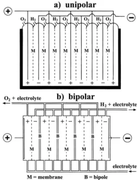
Regarding the cell configuration, electrolyzers may be constructed in either unipolar or bipolar design (Figure 8). A unipolar (or “tank--type”) electrolyzer (Figure 8a) consists of alternate positive and
negative electrodes held apart by porous separators, i.e., membranes. Positive electrodes are all coupled together in parallel, as are the negative electrodes, and the whole assembly is immersed in a single electrolyte bath (“tank”) to form a unit cell. A plant-scale electrolyzer is then built up by connecting these units electrically in series. The total voltage applied to the whole electrolysis cell is the same as that applied to the individual unit cells.
On the other hand, in a bipolar electrolyzer a metal sheet (or “bipole”) connects electrically adjacent cells in series. As seen in Figure 8b, the electrocatalyst for the negative electrode is coated on one face of the bipole and that for the positive electrode of the adjacent cell is coated on the reverse face. In this case, the total cell voltage is the sum of the individual unit cell voltages. Therefore, a series-connected stack of such cells forms a module that operates at a higher voltage and lower current than the tank-type (unipolar) design. To meet the requirements of a large electrolysis plant, these modules are connected in parallel so as to increase the current.
These two different cell configurations present different electrode reactions. For the unipolar configuration, the same electrochemical reaction (either the HER or the OER) occurs on both sides of each electrode. On the other hand, in the bipolar configuration, two different reactions (HER and OER) take place simultaneously on the opposite sides of each electrode not directly connected to the power source. This means that one side of each electrode acts as a cathode and the other as an anode (although both sides are at the same potential), with the exception of the two end electrodes that are connected to the DC power source. The resulting cell voltage for these two basic configurations is quite different. For typical industrial processes, the unipolar configura-tion presents a cell voltage of about 2.2 V and the bipolar configuraconfigura-tion has a value of 2.2 × (n − 1) V (where n is the number of electrodes).1
Owing to the simplicity of the unipolar configuration, this type of electrolyzer is easy to fabricate and requires low maintenance, but presents high electrical currents at low voltages, causing large Ohmic losses. On the other hand, the bipolar configuration has lower Ohmic losses in the electrical circuit connectors; however, it demands much higher precision in its design and manufacturing to prevent electrolyte and gas leakage between cells.1