Resilient Intrusion Tolerance through
Proactive and Reactive Recovery
Paulo Sousa
Alysson Neves Bessani
Miguel Correia
Nuno Ferreira Neves
Paulo Verissimo
DI–FCUL
TR–07–17
October 2007
Departamento de Inform´atica
Faculdade de Ciˆencias da Universidade de Lisboa
Campo Grande, 1749–016 Lisboa
Portugal
Technical reports are available at http://www.di.fc.ul.pt/tech-reports. The files are stored in PDF, with the report number as filename. Alternatively, reports are available by post from the above address.
Resilient Intrusion Tolerance through
Proactive and Reactive Recovery
Paulo Sousa Alysson Neves Bessani Miguel Correia
Nuno Ferreira Neves Paulo Verissimo
Departamento de Inform´atica
Faculdade de Ciˆencias da Universidade de Lisboa Campo Grande, 1749-016 Lisboa - Portugal∗
October 2007
Abstract
Previous works have studied how to use proactive recovery to build intrusion-tolerant replicated systems that are resilient to any number of faults, as long as recoveries are faster than an upper-bound on fault production assumed at system deployment time. In this work, we propose a complementary approach that combines proactive recovery with services that allow correct replicas to react and recover replicas that they detect or suspect to be compromised. One key feature of our proactive-reactive recovery approach is that, despite recoveries, it guarantees the availability of the minimum amount of system replicas necessary to sustain system’s correct operation. We design a proactive-reactive recovery service based on a hybrid distributed system model and show, as a case study, how this service can effectively be used to augment the resilience of an intrusion-tolerant firewall adequate for the protection of critical infrastructures.
Keywords: Intrusion Tolerance, Proactive Recovery, Reactive Recovery, Firewall.
1
Introduction
One of the most challenging requirements of distributed systems being developed nowadays is to ensure that they operate correctly despite the occurrence of accidental and malicious faults (including security attacks and intrusions). This problem is specially relevant for an important class of systems that are
∗This work was partially supported by the EC through project IST-2004-27513 (CRUTIAL) and NoE IST-4-026764-NOE
(RESIST), and by the FCT through project POSI/EIA/60334/2004 (RITAS) and the Large-Scale Informatic Systems Laboratory (LaSIGE).
employed in mission-critical applications such as the SCADA systems used to manage critical infras-tructures like the Power grid. One approach that promises to satisfy this requirement and that gained momentum recently is intrusion tolerance [31]. This approach recognizes the difficulty in building a completely reliable and secure system and advocates the use of redundancy to ensure that a system still delivers its service correctly even if some of its components are compromised.
A problem with “classical” intrusion-tolerant solutions based on Byzantine fault-tolerant replication algorithms is the assumption that the system operates correctly only if at most f out of n of its replicas are compromised. The problem here is that given a sufficient amount of time, a malicious and intelligent adversary can find ways to compromise more than f replicas and collapse the whole system.
Recently, some works showed that this problem can be solved (or at least minimized) if the replicas are rejuvenated periodically, using a technique called proactive recovery [21]. These previous works propose intrusion-tolerant replicated systems that are resilient to any number of faults [5, 34, 4, 17, 25]. The idea is simple: replicas are periodically rejuvenated to remove the effects of malicious attacks/faults. Rejuvenation procedures may change the cryptographic keys and/or load a clean version of the operating system. If the rejuvenation is performed sufficiently often, then an attacker is unable to corrupt enough replicas to break the system. Therefore, using proactive recovery, one can increase the resilience of any intrusion-tolerant replicated system able to tolerate up to f faults/intrusions: an unbounded number of intrusions may occur during its lifetime, as long as no more than f occur between rejuvenations. Both the interval between consecutive rejuvenations and f must be specified at system deployment time according to the expected rate of fault production.
An inherent limitation of proactive recovery is that a malicious replica can execute any action to disturb the system’s normal operation (e.g., flood the network with arbitrary packets) and there is little or nothing that a correct replica (that detects this abnormal behavior) can do to stop/recover the faulty replica. Our observation is that a more complete solution should allow correct replicas that detect or suspect that some replica is faulty to accelerate the recovery of this replica. We named this solution as proactive-reactive recoveryand claim that it may improve the overall performance of a system under attack by reducing the amount of time a malicious replica has to disturb system normal operation with-out sacrificing periodic rejuvenation, which ensures that even dormant faults will be removed from the system.
overall resilience of intrusion-tolerant systems that seek perpetual unattended correct operation. The key property of our approach is that, as long as the fault exhibited by a replica is detectable, this replica will be recovered as soon as possible, ensuring that there is always an amount of system replicas available to sustain system’s correct operation. To the best of our knowledge, we are the first to combine reactive and proactive recovery in a single approach.
We recognize that perfect Byzantine failure detection is impossible to attain in a general way, since what characterizes a malicious behavior is dependent on the application semantics [9, 10, 1, 13]. How-ever, we argue that an important class of malicious faults can be detected, specially the ones generated automatically by malicious programs such as virus, worms, and even botnets. These kinds of attacks have little or no intelligence to avoid being detected by replicas carefully monitoring the environment. However, given the imprecisions of the environment, some behaviors can be interpreted as faults, while in fact they are only effects of overloaded replicas. In this way, a reactive recovery strategy must address the problem of (possible wrong) suspicions to ensure that recoveries are scheduled according to some fair policy in such a way that there is always a sufficient number of replicas for the system to be avail-able. In fact, dealing with imperfect failure detection is the most complex aspect of the proactive-reactive recovery service proposed in this work.
In order to show how the proactive-reactive recovery service can be used to enhance the depend-ability of a system and to evaluate the effectiveness of this approach, we applied it to the construction of an intrusion-tolerant protection device (a kind of firewall) for critical infrastructures. This device, called CIS (CRUTIAL Information Switch) Protection Service, CIS for short, is a fundamental component of an architecture for critical infrastructures protection proposed by some of the authors recently [30] in the context of the EU-IST CRUTIAL project1. The CIS augmented with proactive-reactive recovery represents a very strong and dependable solution for the critical infrastructures protection problem: this firewall is shown to resist powerful Denial-of-Service (DoS) attacks from both outside hosts (e.g., lo-cated somewhere in the Internet) and inside compromised replicas, while maintaining availability and an adequate throughput for most critical infrastructures’ applications.
This work presents the following contributions: (i.) it introduces the concept of proactive-reactive recovery and presents a design for a generic proactive-reactive recovery service that can be integrated in any intrusion-tolerant system; (ii.) it shows how imperfect failure detection (i.e., suspicions) can
be managed to recover suspected replicas without sacrificing the availability of the overall system; and (iii.)it presents and evaluates an intrusion-tolerant perpetually resilient firewall for critical infrastructure protection, which uses the proactive-reactive recovery service.
2
Proactive-Reactive Recovery
Recently, some of the authors showed that proactive recovery can only be implemented with a few syn-chrony assumptions [26, 24]: in short, in an asynchronous system a compromised replica can delay its recovery (e.g., by making its local clock slower) for a sufficient amount of time to allow more than f replicas to be attacked. To overcome this fundamental problem, the approach proposed in this work is based on a hybrid system model [29]. Before presenting the proactive-reactive approach and its founda-tion model, we precisely state the system model on which it is based.
2.1 System Model
We consider a hybrid system model [29] in which the system is composed of two parts, with distinct properties and assumptions, let us call them payload and wormhole.
Payload. Any-synchrony system with n ≥ a f + bk + 1 replicas P1, ..., Pn. For the purpose of our work,
this part can range from fully asynchronous to fully synchronous. At most f replicas can be subject to Byzantine failuresin a given recovery period and at most k replicas can be recovered at the same time. The exact threshold depends on the application. For example, an asynchronous Byzantine fault-tolerant state machine replication system requires n ≥ 3 f + 2k + 1 while the CIS presented in Section 3 requires only n ≥ 2 f + k + 1. If a replica does not fail between two recoveries it is said to be correct, otherwise it is said to be faulty. We assume fault-independence for payload replicas, i.e., the probability of a replica being faulty is independent of the occurrence of faults in other replicas. This assumption can be substantiated in practice through the extensive use of several kinds of diversity [20].
Wormhole. Synchronous subsystem with n local wormholes in which at most f local wormholes can fail by crash. These local wormholes are connected through a synchronous and secure control channel, isolated from other networks. There is one local wormhole per payload replica and we assume that when a local wormhole i crashes, the corresponding payload replica i crashes together. Since the local wormholes are synchronous and the control channel used by them is isolated and synchronous too, we
assume several services in this environment:
1. wormhole clocks have a known precision, obtained by a clock synchronization protocol; 2. there is point-to-point timed reliable communication between every pair of local wormholes; 3. there is a timed reliable broadcast primitive with bounded maximum transmission time [12]; 4. there is a timed atomic broadcast primitive with bounded maximum transmission time [12].
One should note that all of these services can be easily implemented in the crash-failure synchronous distributed system model [28].
2.2 The Proactive Resilience Model (PRM)
The PRM [25] defines a system enhanced with proactive recovery through a model composed of two parts: the proactive recovery subsystem and the payload system, the latter being proactively recovered by the former. Each of these two parts obeys different timing assumptions and different fault models, and should be designed accordingly. The payload system executes the “normal” applications and protocols. Thus, the payload synchrony and fault model entirely depend on the applications/protocols executing in this part of the system. For instance, the payload may operate in an asynchronous Byzantine way. The proactive recovery subsystem executes the proactive recovery protocols that rejuvenate the applica-tions/protocols running in the payload part. This subsystem is more demanding in terms of timing and fault assumptions, and it is modeled as a distributed component called Proactive Recovery Wormhole (PRW).
The distributed PRW is composed of a local module in every host called the local PRW, which may be interconnected by a synchronous and secure control channel. The PRW executes periodic reju-venations through a periodic timely execution service with two parameters: TP and TD. Namely, each
local PRW executes a rejuvenation procedure F in rounds, each round is initiated within TP from the
last triggering, and the execution time of F is bounded by TD. Notice that if local recoveries are not
coordinated, then the system may present unavailability periods during which a large number (possibly all) replicas are recovering. For instance, if the replicated system tolerates up to f arbitrary faults, then it will typically become unavailable if f + 1 replicas recover at the same time, even if no “real” fault occurs. Therefore, if a replicated system able to tolerate f Byzantine servers is enhanced with periodic recoveries, then availability is guaranteed by (i.) defining the maximum number of replicas allowed to
recover in parallel (call it k); and (ii.) deploying the system with a sufficient number of replicas to tolerate f Byzantine servers and k simultaneous recovery servers.
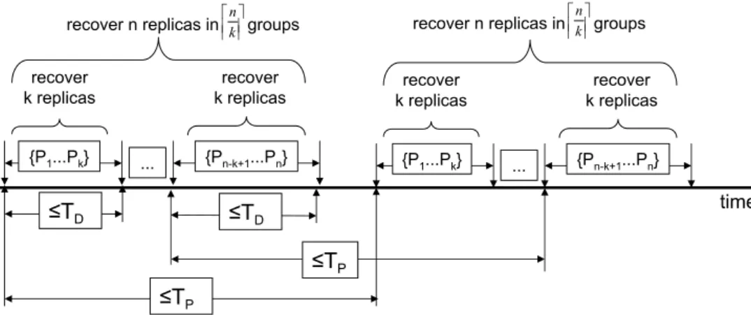
Figure 1 illustrates the rejuvenation process. Replicas are recovered in groups of at most k elements, by some specified order: for instance, replicas {P1, ..., Pk} are recovered first, then replicas {Pk+1, ..., P2k}
follow, and so on. Notice that k defines the number of replicas that may recover simultaneously, and consequently the number of distinct dnke rejuvenation groups that recover in sequence. For instance, if k= 2, then at most two replicas may recover simultaneously in order to guarantee availability. This means also that at least dn2e rejuvenation groups (composed of two replicas) will need to exist, and they can not recover at the same time. Notice that the number of rejuvenation groups determines a lower-bound on the value of TP and consequently defines the minimum window of time an adversary has to
compromise more than f replicas. From the figure it is easy to see that TP≥ dnkeTD.
time {P1...Pk} ... {Pn-k+1...Pn}
recover
k replicas k replicasrecover
{P1...Pk} ... {Pn-k+1...Pn} ≤TP ≤TD recover k replicas recover k replicas recover n replicas in groups
≤TP ≤TD k n
recover n replicas in groups kn
Figure 1: Relationship between the rejuvenation period TP, the rejuvenation execution time TD, and k.
2.3 The Proactive-Reactive Recovery Wormhole (PRRW)
The PRRW offers a single service: the proactive-reactive recovery service. This service needs input information from the payload replicas in order to trigger reactive recoveries. This information is obtained through two interface functions: W suspect( j) and W detect( j). Figure 2 presents this idea.
A payload replica i calls W suspect( j) to notify the PRRW that the replica j is suspected of being failed. This means that replica i suspects replica j but it does not know for sure if it is really failed. Oth-erwise, if replica i knows without doubt that replica j is failed, then W detect( j) is called instead. Notice that the service is generic enough to deal with any kind of replica failures, e.g., crash and Byzantine. For instance, replicas may: use an unreliable crash failure detector [6] (or a muteness detector [9]) and
Replica 1 PRRW
…
W_suspect(j) W_detect(j) Replica 2 W_suspect(j) W_detect(j) Replica n W_suspect(j) W_detect(j) Figure 2: PRRW architecture.call W suspect( j) when a replica j is suspected of being crashed; or detect that a replica j is sending unexpected messages or messages with incorrect content [1, 13], calling W detect( j) in this case.
If f + 1 different replicas suspect and/or detect that replica j is failed, then this replica is recovered. This recovery can be done immediately, without endangering availability, in the presence of at least f + 1 detections, given that in this case at least one correct replica detected that replica j is really failed. Other-wise, if there are only f + 1 suspicions, the replica may be correct and the recovery must be coordinated with the periodic proactive recoveries in order to guarantee that a minimum number of correct replicas is always alive to ensure the system availability. The quorum of f + 1 in terms of suspicions or detections is needed to avoid recoveries triggered by faulty replicas: at least one correct replica must detect/suspect a replica for some recovery action to be taken.
As will be made clear in the next sections, we do not provide any means for a replica to “unsuspect” some other replica it previously suspected. We choose to not provide this service to avoid complica-tions with the computation of f + 1 suspects (some replicas could see it while others not) and because suspicions are cleaned when the replica is recovered.
It is worth to notice that the service provided by the proactive-reactive recovery wormhole is com-pletely orthogonal to the failure/intrusion detection strategy used by a system. The proposed service only exports operations to be called when a replica is detected/suspected to be faulty. In this sense, any approach for fault detection (including Byzantine) [6, 9, 1, 13], system monitoring [7] and/or intrusion detection [8, 18] can be integrated in a system that uses the PRRW. The overall effectiveness of our ap-proach, i.e., how fast a compromised replica is recovered, is a direct consequence of detection/diagnosis accuracy.
2.3.1 Scheduling Recoveries without Harming Availability
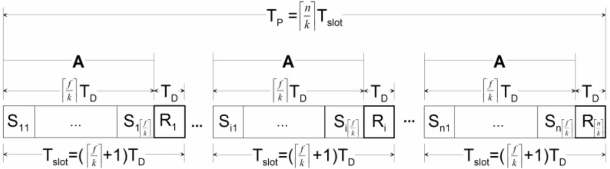
The proactive-reactive recovery service initiates recoveries both periodically (time-triggered) and when-ever something bad is detected or suspected (event-triggered). As explained in Section 2.2, periodic recoveries are done in groups of at most k replicas, so no more than k replicas are recovering at the same time. However, the interval between the recovery of each group is not tight. Instead we allocate dkfe in-tervals for recovery between periodic recoveries such that they can be used by event-triggered recoveries. This amount of time is allocated to make possible at most f recoveries between each periodic recovery, in this way being able to handle the maximum number of faults assumed.
The approach is based on real-time scheduling with an aperiodic server task to model aperiodic tasks [27]. The idea is to consider the action of recovering as a resource and to ensure that no more than kcorrect replicas will be recovering simultaneously. As explained before, this condition is important to ensure that the system always stays available. Two types of real-time tasks are utilized by the proposed mechanism:
• task Ri: represents the periodic recovery of up to k replicas (in parallel). All these tasks have worst
case execution time TDand period TP;
• task A: is the aperiodic server task, which can handle at most dkfe recoveries (of up to k replicas) every time it is activated. This task has worst case execution time dkfeTDand period (dkfe + 1)TD.
Task Riis executed at up to k different local wormholes, while task A is executed in all wormholes,
but only the ones with the payload detected/suspected of being faulty are (aperiodically) recovered. The time needed for executing one A and one Ri is called the recovery slot i and is denoted by Tslot. Every
slot i has dkfe recovery subslots belonging to the A task, each one denoted by Sip, plus a Ri. Figure 3
illustrates how time-triggered periodic and event-triggered aperiodic recoveries are combined.
In the figure it is easy to see that when our reactive recovery scheduling approach is employed, the value of TPmust be increased. In fact, TP should be greater or equal than dnke(dkfe + 1)TD, which means
that reactive recoveries increase the rejuvenation period by a factor of (dkfe + 1). This is not a huge increase since f is expected to be small. In order to simplify the presentation of the algorithms, in the remaining of the report it is assumed that TP= dnke(dkfe + 1)TD.
Notice that a reactive recovery only needs to be scheduled according to the described mechanism if the replica i to recover is only suspected of being failed (it is not assuredly failed), i.e., if less than f + 1
Figure 3: Recovery schedule (in an Si j or Risubslot there can be at most k parallel replica recoveries).
replicas have called W detect() (but the total number of suspicions and detections is higher than f + 1). If the wormhole Wi knows with certainty that replica i is faulty, i.e., if a minimum of f + 1 replicas have
called W detect(i), replica i can be recovered without availability concerns, since it is accounted as one of the f faulty replicas.
2.3.2 The PRRW Algorithm
The proactive-reactive recovery service presented in Algorithm 1 is now explained in detail. The algo-rithms executed inside the PRRW are implemented as threads in a real-time environment with a pre-emptive schedulerwhere static priorities are defined from 1 to 3 (priority 1 being the highest). In these algorithms we do not consider explicitly the clock skew and drift, since we assume that these deviations are small due to the periodic clock synchronization, and thus are compensated in the protocol parameters (i.e., in the time bounds for the execution of certain operations).
Parameters and variables. This algorithm uses six parameters: i, n, f , k, TP, and TD. The id of the local
wormhole is represented by i; n specifies the total number of replicas and consequently the total number of local wormholes; f defines the maximum number of faulty replicas; k specifies the maximum number of replicas that recover at the same time; TP defines the maximum time interval between consecutive
triggers of the recovery procedure (depicted in Figure 3); and TD defines the worst case execution time
of the recovery of a replica. Additionally, four variables are defined: tnext stores the instant when the
next periodic recovery should be triggered by local wormhole i; the Detect set contains the processes that detected the failure of replica i; the Suspect set contains the processes that suspect replica i of being failed; and scheduled indicates if a reactive recovery is scheduled for replica i.
Reactive recovery service interface. W suspect( j) and W detect( j) send, respectively, a SUSPECT or DETECT message to wormhole j, which is the wormhole in the suspected/detected node (lines 1-2).
Algorithm 1 Wormhole proactive-reactive recovery service.
{Parameters}
integer i {Id of the local wormhole} integer n {Total number of replicas}
integer f {Maximum number of faulty replicas} integer k {Max. replicas that recover at the same time} integer TP{Periodic recovery period}
integer TD{Recovery duration time}
{Constants} integer Tslot, (df
ke + 1)TD{Slot duration time}
{Variables}
integer tnext = 0 {Instant of the next periodic recovery
start}
set Detect = ∅ {Processes that detected me as failed} set Suspect = ∅ {Processes suspecting me of being failed} bool scheduled = false {Indicates if a reactive re-covery is scheduled for me}
{Reactive recovery interface threads with priority 3} service W suspect( j)
1: send( j, hSUSPECTi) service W detect( j)
2: send( j, hDETECTi) upon receive( j, hSUSPECTi)
3: Suspect← Suspect ∪ { j} upon receive( j, hDETECTi)
4: Detect← Detect ∪ { j}
{Periodic recovery thread with priority 1} procedure proactive recovery()
5: synchronize global clock()
6: tnext← global clock() + (di−1k eTslot+ dkfeTD)
7: loop
8: wait until global clock() = tnext
9: recovery() 10: tnext= tnext+ TP 11: end loop procedure recovery() 12: recovery actions() 13: Detect← ∅ 14: Suspect← ∅ 15: scheduled← false
{Reactive recovery execution threads with priority 2} upon |Detect| ≥ f + 1
16: recovery()
upon (|Detect| < f + 1) ∧ (|Suspect ∪ Detect| ≥ f + 1)
17: if ¬scheduled then
18: scheduled← true
19: hs, ssi ← allocate subslot()
20: if s 6= di
ke then
21: wait until global clock() mod TP = sTslot+
ssTD
22: if |Suspect ∪ Detect| ≥ f + 1 then recovery()
23: end if
24: end if
When a local wormhole i receives such a message from wormhole j, j is inserted in the Suspect or Detect set according to the type of the message (lines 3-4). The content of these sets may trigger a recovery procedure.
Proactive recovery. The proactive recovery() procedure is triggered by each local wormhole i at boot time (lines 5-11). It starts by calling a routine that synchronizes the clocks of the local wormholes with the goal of creating a virtual global clock, and blocks until all local wormholes call it and can start at the same time. When all local wormholes are ready to start, the virtual global clock is initialized at (global) time instant 0 (line 5). The primitive global clock() returns the current value of the (virtual) global clock. After the initial synchronization, the variable tnext is initialized (line 6) in a way that local wormholes
trigger periodic recoveries in groups of up to k replicas according to their id order, and the first periodic recovery triggered by every local wormhole is finished within TPfrom the initial synchronization. After
this initialization, the procedure enters an infinite loop where a periodic recovery is triggered within TP
function recovery actions() (line 12) that should be implemented according to the logic of the system using the PRRW. Typically, a recovery starts by saving the state of the local replica if it exists, then the payload operating system (OS) is shutdown and its code is restored from some read-only medium, and finally the OS is booted, bringing the replica to a supposedly correct state. The last three lines of the recovery() procedure re-initialize some variables because the replica should now be correct (lines 13-15). Reactive recovery. Reactive recoveries can be triggered in two ways: (1) if the local wormhole i receives at least f + 1 DETECT messages, then recovery is initiated immediately because replica i is accounted as one of the f faulty replicas (line 16); (2) otherwise, if f + 1 DETECT or SUSPECT messages arrive, then replica i is at best suspected of being failed by one correct replica. In both cases, the f + 1 bound ensures that at least one correct replica detected a problem with replica i. In the suspect scenario, recovery does not have to be started immediately because the replica might not be failed. Instead, if no reactive recovery is already scheduled (line 17), the aperiodic task finds the closest slot where the replica can be recovered without endangering the availability of the replicated system. The idea is to allocate one of the (reactive) recovery subslots depicted in Figure 3. This is done through the function allocate subslot() (line 19 – explained later). Notice that if the calculated subslot hs, ssi is located in the slot where the replica will be proactively recovered, i.e., if s = dkie, then the replica does not need to be reactively recovered (line 20). If this is not the case, then local wormhole i waits for the allocated subslot and then recovers the corresponding replica (lines 21-22). Notice that the expression global clock() mod TPreturns the time
elapsed since the beginning of the current period, i.e., the position of the current global time instant in terms of the time diagram presented in Figure 3.
Recovery subslot allocation. Subslot management is based on accessing a data structure replicated in all wormholes through a timed total order broadcast protocol, as described in Algorithm 2. This algorithm uses one more parameter and one more variable besides the ones defined in Algorithm 1. The parameter T∆ specifies the upper-bound on the delivery time of a message sent through the synchronous control
network connecting all the local wormholes. Variable Subslot is a table that stores the number of replicas (up to k) scheduled to recover at each subslot of a recovery slot, i.e., Subslot[hs, ssi] gives the number of processes using subslot ss of slot s (for a maximum of k). This variable is used to keep the subslot occupation, allowing the local wormholes to find the next available slot when it is necessary to recover a suspected replica.
Algorithm 2 PRRW recovery slot allocation.
{Parameters (besides the ones defined in Algorithm 1)} integer T∆{Bound on message delivery time}
{Variables (besides the ones defined in Algorithm 1)}
table Subslot[h1, 1i...hdnke, dkfei] = 0 {Number of processes scheduled to recover at each subslot of a recovery slot}
procedure allocate subslot()
1: TO-multicast(hALLOC, i, global clock()i)
2: wait until TO-receive(hALLOC, i,tsendi)
3: return local allocate subslot(tsend) upon TO-receive(hALLOC, j,tsendi) ∧ j 6= i
4: local allocate subslot(tsend)
procedure local allocate subslot(tsend)
5: tround← (tsend+ T∆) mod TP
6: curr subslot← hbtround
Tslotc + 1, btroundmod Tslotc + 1i 7: loop
8: curr subslot← next subslot(curr subslot)
9: if Subslot[curr subslot] < k then
10: Subslot[curr subslot] ←
Subslot[curr subslot] + 1
11: return curr subslot
12: end if
13: end loop
procedure next subslot(hs, ssi)
14: if ss < dkfe then 15: ss← ss + 1 16: else if s < dn ke then 17: ss← 0; s ← s + 1 18: else 19: ss← 0; s ← 0 20: end if 21: return hs, ssi
upon (tround← (global clock() mod TP)) mod Tslot= 0
22: if btround
Tslot c = 0 then 23: prev slot← dn
ke
24: else
25: prev slot← btround
Tslotc 26: end if
27: ∀p, Subslot[hprev slot, pi] ← 0
which timestamps and sends an ALLOC message using total order multicast (line 1) to all local worm-holes and waits until this message is received (line 2). At this point the function local allocate subslot() is called and the next available subslot is allocated to the replica (line 3). The combination of total order multicast with the sending timestamp Tsend ensures that all local wormholes allocate the same subslots
in the same order. The local allocation algorithm is implemented by the local allocate subslot(Tsend)
function (lines 5-13). This function manages the various recovery subslots and assigns them to the repli-cas that request to be recovered. It starts by calculating the first subslot that may be used for a recovery according to the latest global time instant when the ALLOC message may be received by any local wormhole (lines 5-6), then it searches and allocates the next available subslot, i.e., a slot in the future that has less than k recoveries already scheduled (lines 7-21). Finally, in the beginning of each recovery slot, all the subslots of the previous recovery slot are deallocated (lines 22-27).
3
Case Study: The CIS Protection Service
In this section we describe how the PRRW component can be extended and integrated to make a perpetual-resilient operational system. The described system is a protection device for critical
infor-mation infrastructures (a kind of improved application layer firewall) called CIS Protection Service. Here we only present a high-level view of the system focusing in the PRRW integration, the complete description of this system is presented in [3].
3.1 Context and Motivation
Today’s critical infrastructures like the Power Grid are essentially physical processes controlled by com-puters connected by networks. Once these systems were highly isolated and secure against most security threats. However, in recent years they evolved in several aspects that greatly increased their exposure to cyber-attacks coming from the Internet. Firstly, the computers, networks and protocols used in these systems are no longer proprietary and specific, but standard PCs and networks. Second, most of them are connected to the Internet and corporate networks. Therefore these infrastructures have a level of vulner-ability similar to other systems connected to the Internet, but the socio-economic impact of their failure can be huge. This scenario, reinforced by several recent incidents [32], is generating a great concern about the security of these infrastructures, especially at government level.
Recently, some of the authors proposed a reference architecture to protect critical infrastructures, in the context of the CRUTIAL EU-IST project [30]. The idea is to model the whole infrastructure as a set of protected LANs, representing the typical facilities that compose it (e.g., power transformation substations or corporate offices), which are interconnected by a wider-area network (WAN). Using this architecture, we reduce the problem of critical infrastructures protection to the problem of protecting LANs from the WAN or other LANs. In consequence, our model and architecture allow us to deal both with outsider threats (protecting a facility from the Internet) and insider threats (protecting a critical host from other hosts in the same physical facility, by locating them in different LANs). A fundamental component of this architecture is the CRUTIAL Information Switch (CIS), which is deployed at the borders of a LAN and is reasonable to connect this LAN with the others and to protect it. This second requirement is implemented by the CIS Protection Service, which ensures that the incoming and outgoing traffic in/out of the LAN satisfies the security policy of the infrastructure.
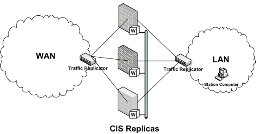
A CIS can not be a simple firewall since that would put the critical infrastructure at most at the level of security of current (corporate) Internet systems, which is not acceptable since intrusions in those systems are constantly being reported. Instead, the CIS has several different characteristics, being the most important its intrusion tolerance, i.e., it operates correctly even if there are intrusions in some of
Traffic Replicator Traffic Replicator
Station Computer
W
W
W
Figure 4: Intrusion-tolerant CIS protection service.
its components and withstands a high degree of such hostility from the environment, seeking unattended perpetual operation. In the next sections we show how the basic intrusion-tolerant design for the CIS can be integrated to the PRRW to make it attain perpetual correction.
3.2 How the CIS Works
The intrusion-tolerant CIS is replicated in a set of n ≥ 2 f + 1 machines2connected both to the protected LAN and the insecure WAN through traffic replication devices (e.g., a hub or a switch). Figure 4 depicts the intrusion-tolerant CIS architecture.
The CIS design presents two very interesting challenges that make it essentially different from other Byzantine fault-tolerant services. The first is that a firewall-like component has to be transparent to protocols that pass through it, so it can not modify the protocols themselves to obtain intrusion toler-ance. This also means that recipient nodes (inside the protected network) will ignore any internal CIS intrusion-tolerance mechanisms, and as such they can not protect themselves from messages forwarded by faulty replicas not satisfying the security policy. These two challenges are solved through the use of wormholes [29]: we assume that each replica of the CIS has a trusted component (the W boxes in Figure 4) that cannot be corrupted. These local wormholes are connected through an isolated network. Moreover, each CIS replica is deployed in a different operating system (e.g., Linux, FreeBSD, Windows XP), and the operating systems are configured to use different passwords.
In a nutshell, the message processing is done in the following way: each CIS replica receives all
2The CIS design presented here assumes that policies are stateless. In [3] we explain how statefull policies could be
packets to the LAN and verifies if these packets satisfy some pre-defined application-level security policy. If a message is in accordance with some policy, it is accepted by the CIS, and must be forwarded to its destination in the LAN. Every message approved by a replica is issued to the wormhole to be signed. The local wormholes vote between themselves and, if the message is approved by at least f + 1 replicas, it is signed using a secret key installed in the wormhole component. Once the message is signed, one of the replicas (the leader) is responsible for forwarding the approved message to its destination. Besides message signing, the wormhole is responsible also for leader election. The traffic replication devices in Figure 4 are responsible for broadcasting the WAN and LAN traffic to all replicas. The LAN replication device is specially useful to detect if malicious replicas send non-approved messages to the LAN.
3.3 Integrating the CIS and the PRRW
There are two main issues that must be addressed when integrating the PRRW into an intrusion-tolerant application: the implementation of the recovery actions() procedure (i.e., what actions are done when it is time to recover a replica) and defining in which situations the W suspect and W detect PRRW services are called by a replica.
In the case of the CIS, the recovery actions() comprise the execution of the following sequence of steps:
1. if the replica to be recovered is the current CIS leader, then a new leader must be elected: a message is sent by the local wormhole of the current leader to all local wormholes informing that the new leader is the last replica that finished its periodic recovery;
2. the replica is deactivated, i.e., its operating system is shutdown;
3. the replica operating system is restored using some clean image (that can be different from the previous one);
4. the replica is activated with its new operating system image.
Step 1 is needed only because our replication algorithm requires a leader and the wormhole is re-sponsible to maintain it. In step 3 the wormhole can select one from several pre-generated operating system images to be installed on the recovered replica. These images can be substantially different
(different operating systems, kernel versions, configurations, access passwords, etc.) to enforce fault in-dependence between recoveries. In step 4 we assume that when the system is rebooted the CIS software is started automatically.
The PRRW services for informing suspicions and detections of faults are called by the CIS replicas when they observe something that was not supposed to happen and/or when something that was suppose to happen does not occur. In the case of the CIS, the constant monitoring of the protected network allows a replica to detect some malicious behaviors from other replicas. Notice that this can only be done because our architecture (Figure 4) has a traffic replication device inside the LAN (ensuring that all replicas see all messages sent by every other replica to the LAN) and it is assumed that all messages sent by the CIS replicas to the LAN are authenticated3.
Currently, there are two situations in which the PRRW services are called:
(i.) Some replica sends an invalid message to the protected network: if a correct replica detects that some other replica sent an illegal message (one that was not signed by the wormhole) to the LAN, it can detect this replica as faulty and call W detect informing that the replica presented a faulty behaviour. From Algorithm 1 it can be seen that when f + 1 replicas detect a faulty replica, it is recovered;
(ii.) The leader fails to forward a certain number of approved messages: if a correct replica knows that some message was approved by the wormhole and it does not see this message being forwarded to the LAN it can conclude that something is wrong with the current leader (which was supposed to forward the message). Due to the many imprecisions considered in the system (asynchrony, replica’s message losses due to high traffic), it is perfectly possible that a correct leader did not received the message to be approved or, this message was forwarded but some replica did not receive it from the LAN. To cope with this, we define an omission threshold for the leader which defines the maximum number of omissions that a replica can perceive from some leader replica before suspecting it to be faulty. Notice that it is impossible to know with certainty if the leader is faulty, so replicas call W suspect and not W detect in this case. From Algorithm 1 it can be seen that when f + 1 replicas suspect a faulty replica, a recovery is scheduled for it.
As will be seen in Section 4, these two interactions between the replicas and the PRRW service makes much more difficult for a malicious adversary to launch any attack to the protected LAN (in the sense that it will have much less time). The proof that this design for the CIS is correct and attains
perpetual resilience can be found in [3].
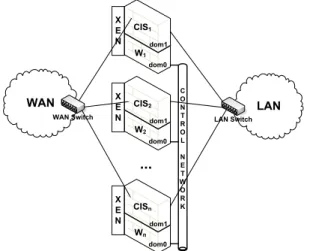
3.4 Prototype
Our implementation uses the XEN virtual machine monitor [2] with the Linux operating system. The architecture is presented in Figure 5. A XENsystem has multiple layers, the lowest and most privileged of which is XENitself. XEN may host multiple guest operating systems, every one executed within an isolated VM or, in XEN terminology, a domain. Domains are scheduled by XEN to make effective use
of the available physical resources (e.g., CPUs). Each guest OS manages its own applications. The first domain, dom0, is created automatically when the system boots and has special management privileges. Domain dom0 builds other domains (dom1, dom2, dom3, ...) and manages their virtual devices. It also performs administrative tasks such as suspending and resuming other VMs, and it can be configured to execute with higher priority than the remaining VMs.
X E N X E N X E N WAN Switch CIS1 C O N T R O L N E T W O R K LAN Switch dom0 dom1 W1 CIS2 dom0 dom1 W2 CISn dom0 dom1 Wn
Figure 5: CIS Prototype architecture.
As depicted in Figure 5, every replica uses XEN to isolate the payload from the wormhole part. Local wormholes run in replicas’ domain dom0, and the CIS protection service executes in replicas’ domain dom1. Domain dom0 is configured to execute with higher priority than domain dom1 in every replica, in order to emulate the real time behavior required by PRRW services. The local wormholes are connected through an isolated control network.
The recovery actions executed by the PRRW make use of XENsystem calls xm destroy and xm create
to, respectively, shutdown and boot a CIS replica. Note that xm destroy corresponds to a virtual power off and it is almost instantaneous, whereas a normal shutdown could take several seconds. We avoid the
delay of a normal shutdown because we assume that the running OS may have been compromised and thus it cannot be reutilized.
In order to provide a virtual global clock to each local wormhole, we implemented a clock synchro-nization protocol. There are many clock synchrosynchro-nization algorithms available in the literature suitable to synchronous environments with crash faults [28]. The protocol we implemented combines techniques proposed on some of these works and it is now briefly explained. Local wormholes are initially launched by any order as long as local wormhole 1 is the last one to begin execution. When local wormhole 1 starts executing, it broadcasts a small synchronization message to all wormholes (including itself) and this message is used by every local wormhole to define the global time instant 0. Then, in order to maintain the virtual global clocks with a bounded precision, each local wormhole broadcasts a synchro-nization message exactly when a proactive recovery is triggered. Given that all local wormholes know when proactive recoveries should be triggered, they can adjust their clocks accordingly. Both mech-anisms assume that the broadcast reception instant is practically the same everywhere in the control network, which is substantiated by the fact that the control network is provided by a switch used only by the local wormholes.
To simplify the design and to avoid changes in the kernel, the CIS prototype operates at the UDP level, instead of IP level as most firewalls do. Therefore, there was no need to implement packet in-terception because packets are sent directly to the CIS. Moreover, authentication is not done at the IP level (as when using IPSEC/AH), but in alternative the wormhole calculates the HMAC4of the payload UDP packet, and then the two are concatenated. Notice that this type of authentication implies the same type of overhead of IP authentication. Given that the CIS prototype operates at the UDP level, we make use of IP multicast to enforce broadcast in WAN and LAN communication. Therefore, we do not need physical traffic replication devices in our prototype5. Moreover, the LAN switch uses access control lists to prevent replicas from spoofing their MAC addresses, and each replica stores a table with the MAC address of each other replica.
Periodic and reactive recoveries reset the state and restore the code of a replica. While this is useful to restore the correctness of the replica, it would be interesting if we were able to introduce diversity in the recovery process. For instance, each recovery could randomize the address space of the replica (e.g.,
4HMAC is a standard for calculating MACs, and in the prototype we used the SHA-1 hash function [19].
5Nevertheless, if the CIS would operate at the IP level, we could configure the WAN and LAN switches to use the failopen
using PAX6) in order to minimize the usefulness of the knowledge obtained in the past to increase the chances of future attacks. The XENand PAX communities are currently making efforts to release a joint distribution, and we plan to integrate this mechanism in the prototype when it is available. Nevertheless, the current version of the prototype already incorporates some diversity mechanisms: we maintain a pool of OS images with different configurations (e.g., different root passwords, different kernel versions) and each recovery (proactive or reactive) randomly chooses and boots one of these images.
Domain dom0 executes with higher priority than domain dom1, but since it is based on a normal Linux OS, it provides no strict real-time guarantees. Currently, only modified versions of Linux and NetBSD can be run on dom0. However, XENis continuously being improved and we expect that in the near future one can use a real-time OS.
4
Experimental Evaluation
The experimental setup was composed by a set of four machines representing the CIS replicas (n = 4) connected to the three networks defined in our prototype architecture: LAN, WAN, and the control network (see Figure 5). These networks were defined as separated VLANs configured on two Dell Gigabit switches. The LAN and control networks shared the same switch, whereas the WAN network was deployed in a different switch. The LAN and WAN were configured as 100 Mbps networks while the control network operated at 1 Gbps. We used three additional PCs in the experiments. One PC was connected to the LAN emulating the station computer and, in the WAN side, two PCs were deployed: a goodsender trying to transmit legal traffic to the station computer, and a malicious sender sending illegal messages to the LAN (equivalent to a DoS attack). Every machine of our setup was a 2.8 GHz Pentium 4 PC with 2 GB RAM running Fedora Core 6 with Linux 2.6.18, and XEN3.0.3 to manage the virtual machines. As explained in Section 3.4, each CIS physical host uses the XEN virtual machine monitor to manage two virtual machines: a non-privileged one with 1536 MB of RAM (dom1 – CIS protection service) and a trusted one with 512 MB of RAM (dom0 – local PRRW).
Recoveries performance. In the first experiment we tried to find appropriate values for parameters TD
(recover time) and TP(recover period). We measured the time needed for each recovery task in a total of
300 recovery procedures executed during CIS operation. Table 1 shows the average, standard deviation,
and maximum time for each recovery task: CIS shutdown, CIS rejuvenation by restoring its disk with a clean image randomly selected from a set of predefined images with different configurations, and the reboot of this new image. All disk images used in this experiment had sizes of approximately 1.7 GB.
Shutdown Rejuvenation Reboot Total
Average 0.6 72.2 70.1 144.6
Std. Deviation 0.5 1.2 0.3 0.9
Maximum 1.0 74.0 71.0 146.0
Table 1: Time needed (in seconds) for the several steps of a replica recovery (1.7 GB OS images).
From Table 1 one can see that a maximum of 146 seconds (∼ 2.5 minutes) are needed in order to completely recover a virtual machine in our environment, being most of this time spent on two tasks: (1.) copying a clean pre-configured disk image from a local repository; and (2.) starting this new image (including starting the CIS protection service). These tasks could have their time lowered if we were able to build smaller images, which was not possible with the current Linux distribution we are using (Fedora Core 6).
The results from the first experiment allowed to define TD= 150 seconds for the remaining
ex-periments described below. Considering that we had n = 4 replicas to tolerate f = 1 faults and k = 1 simultaneous recoveries, we used the expressions defined in Section 2.3.1 to calculate the maximum time between two recoveries of an individual replica as TP= 1200 seconds (20 minutes). By applying
these values to the Proactive Resilience model [25], we conclude that a malicious adversary has at most TP+ TD= 22.5 minutes to compromise more than f replicas and to harm the safety of the proposed
system (i.e., make the CIS sign an illegal message) in our experimental setup.
Latency and throughput under a DoS attack from the WAN. In the second set of experiments, we tried to evaluate how much legal traffic our intrusion-tolerant firewall can deliver while it is being attacked by an outsider. In these experiments there is a good sender (in the WAN) constantly transmitting 1470 bytes’ packets of legal traffic at a rate of 500 packets per second to the station computer7 inside the LAN and there is a malicious sender (in the WAN) launching a DoS attack against the CIS, i.e., sending between 0 and the maximum possible rate (∼ 100 Mbps) of illegal traffic to it. We measured the received message rate at the station computer to obtain the throughput of the CIS (the rate at which it can approve messages) when it has to reject large amounts of illegal traffic. In a different experiment we measured
7It is a huge traffic for a critical infrastructure information system. For example, it represents 500 MMS messages being
the latency imposed by CIS message approval also in the presence of DoS attacks of different rates. In this latency experiment, the good sender sends a packet with 1470 bytes to the station computer that acknowledges it. This acknowledgment is not processed by the CIS and we measured the round-trip time in the good sender. All experiments (bandwidth and latency) were executed 1000 times and Figure 6 shows the average latency and maximum throughput measured in these experiments.
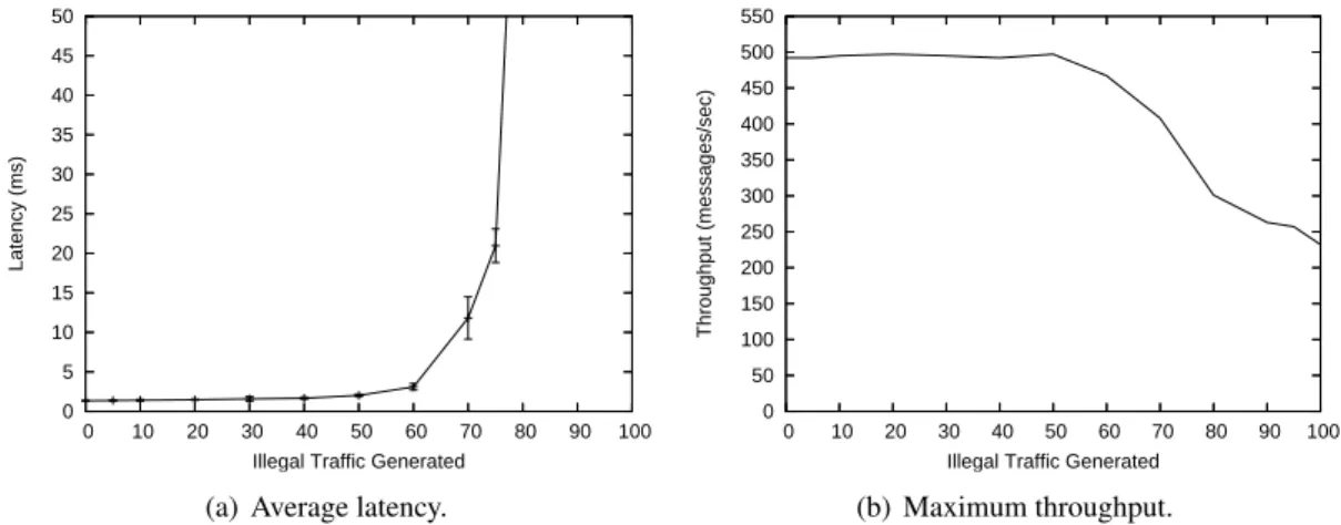
0 5 10 15 20 25 30 35 40 45 50 0 10 20 30 40 50 60 70 80 90 100 Latency (ms)
Illegal Traffic Generated (a) Average latency.
0 50 100 150 200 250 300 350 400 450 500 550 0 10 20 30 40 50 60 70 80 90 100 Throughput (messages/sec)
Illegal Traffic Generated (b) Maximum throughput.
Figure 6: Latency and throughput of the CIS in forwarding legal messages sent by a good sender in the WAN to the station computer in the LAN while a malicious host in the WAN is sending illegal traffic (not approved by the CIS).
The graphs show that the system is almost unaffected by DoS attacks up to 50 Mbps, and then its behavior degrades gracefully until 70 Mbps. After this value, the latency presents a huge increase (Figure 6(a)) and the throughput drops to about 250 messages/sec (Figure 6(b)). For 90-100 Mbps of invalid traffic we observed that sometimes (in 1% of the experiments) the CIS loses some messages (from 15% to 21%), however, it occurs rarely. These results suggest that our design adds modest latency (less than 2 ms) and no throughput loss even with a reasonably loaded network. The results show also that to cope with significant DoS attacks (> 70 Mbps) coming from the unprotected network, complimentary mechanisms must be employed, given that CIS processing latency has a huge increase.
In the third and fourth set of experiments described next, the goal was to evaluate the impact of proactive/reactive recoveries and replicas’ crash/Byzantine faults in the overall system throughput. In these experiments there is not a malicious sender in the WAN, just a good sender constantly transmitting legal traffic at a rate of 5 Mbits per second to the station computer.
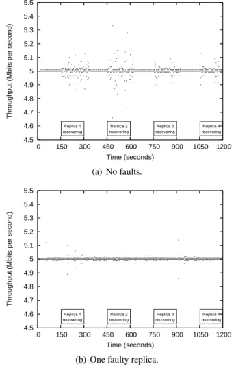
Throughput during recoveries and in the presence of crash faults. The third set of experiments evaluated the impact of proactive recovery and crash faults in the overall system throughput. Figure 7
presents two time diagrams that show the throughput of the CIS during a complete recovery period (20 minutes) without faults and with one crashed (silent) replica.
4.5 4.6 4.7 4.8 4.9 5 5.1 5.2 5.3 5.4 5.5 0 150 300 450 600 750 900 1050 1200
Throughput (Mbits per second)
Time (seconds) Replica 3 recovering Replica 1 recovering Replica 4 recovering Replica 2 recovering (a) No faults. 4.5 4.6 4.7 4.8 4.9 5 5.1 5.2 5.3 5.4 5.5 0 150 300 450 600 750 900 1050 1200
Throughput (Mbits per second)
Time (seconds) Replica 1 recovering Replica 2 recovering Replica 3 recovering Replica 4 recovering
(b) One faulty replica.
Figure 7: Throughput of the CIS during a complete recovery period (20 minutes) with n = 4 ( f = 1 and k= 1), with and without crash faults.
The time diagrams of Figure 7 lead to the following conclusions. First, it can be seen that, with-out faults, recoveries do not have a substantial impact on the perceived throughput of the system (Fig-ure 7(a)). The minimum observed throughput during recoveries was 4.6 Mbits/second, which represents a 8% drop in comparison with the expected throughput of 5 Mbits/second. This can be explained by the fact that proactive recoveries are executed with higher priority than voting procedures and thus may delay their execution during the recovering periods. Second, the occurrence of crash faults also does not affect substantially the throughput of the system, even during periodic recoveries (Figure 7(b)). This happens because we use k = 1 extra replicas to ensure that the system is always available: even with one
fault and one recovery, there are still two correct replicas ( f + 1) to vote and approve messages. Note that without these k extra replicas, the system would become completely unavailable in the recovering periods of Figure 7(b). Third, by comparing the observed throughput with and without crash faults, one can conclude that the impact of proactive recoveries is smaller when there is a crashed replica during the entire execution. This happens because 3 replicas generate less vote messages in the wormhole con-trol channel than 4 replicas. This reduction is sufficient to minimize the impact of the higher priority proactive recoveries on the vote processing time.
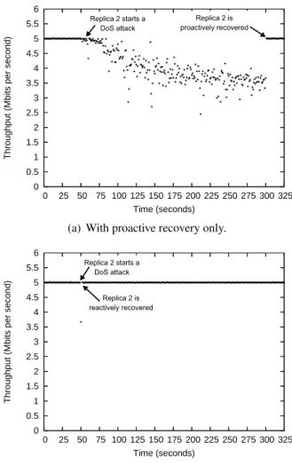
Throughput under a DoS attack from a compromised replica. Finally, the fourth set of experiments measured the resilience of the CIS against Byzantine faults, i.e., in the presence of up to f compromised replicas. Given that the CIS algorithms already tolerate up to f Byzantine faults, we choose a malicious behavior orthogonal to the algorithms logic that could nevertheless endanger the quality of the service provided by the CIS. In this way, we configured one of the CIS replicas (replica 2) to deploy a DoS attack 50 seconds after the beginning of CIS execution. This DoS attack floods the LAN with packets of 1470 bytes sent at a rate of 90 Mbps. We observed how the throughput is affected during this attack and until the replica being recovered. In order to show the effectiveness of our proactive-reactive recov-ery approach, we compared what happens when only proactive recoveries are used, and when they are combined with reactive recoveries. The results are presented in Figure 8.
Figure 8(a) shows that the CIS throughput is affected during the DoS attack from replica 2 when only proactive recovery is used. The throughput decreases during the attack and reaches a minimum value of 2.45 Mbps (half of the expected throughput). The attack is stopped when the local wormhole of replica 2 triggers a proactive recovery after 300 seconds of the initial time instant. Notice that this recovery should be triggered 150 seconds later but given that we assume here that there are no reactive recoveries, we do not need the reactive recovery subslots depicted in Figure 3 and proactive recoveries may be triggered one after the other.
The utility and effectiveness of combining proactive and reactive recoveries is illustrated by Fig-ure 8(b), which shows that the CIS throughput is minimally affected by the DoS attack from replica 2. This attack is detected by the remaining replicas and a reactive recovery is triggered immediately after the attack being launched. The reaction is so fast that the throughput drops to 3.67 Mbps just during one second and then it gets back to the normal values.
0 0.5 1 1.5 2 2.5 3 3.5 4 4.5 5 5.5 6 0 25 50 75 100 125 150 175 200 225 250 275 300 325
Throughput (Mbits per second)
Time (seconds)
Replica 2 starts a DoS attack
Replica 2 is proactively recovered
(a) With proactive recovery only.
0 0.5 1 1.5 2 2.5 3 3.5 4 4.5 5 5.5 6 0 25 50 75 100 125 150 175 200 225 250 275 300 325
Throughput (Mbits per second)
Time (seconds)
Replica 2 starts a DoS attack
Replica 2 is reactively recovered
(b) With proactive and reactive recovery.
Figure 8: Throughput of the CIS during 325 seconds with n = 4 ( f = 1 and k = 1). Replica 2 is malicious and launches a DoS attack to the LAN after 50 seconds. We present graphs with (b) and without (a) reactive recovery.
5
Related Work
Rejuvenation [15, 11] has been proposed in the 90s as a proactive technique to deal with transient failures due to software aging. The idea is to periodically rejuvenate some software components to eliminate and prevent failures. Some works on this field, beginning with [11], developed techniques to choose the optimal rejuvenation period in order to minimize the downtime of the system. None of the works on software rejuvenation assume faults caused by malicious adversaries, so the problem that we deal in this work is much more complicated than software aging.
Several works advocate the use of proactive recovery to make the system tolerate an unbounded number of malicious faults during its lifetime as long as no more than f faults occur during a bounded
time period [5, 34, 4, 17]. Recently, some of the authors showed that all these works have some hidden problems that could be exploited by a smart adversary [24]. The main problem is that these works assume the asynchronous distributed system model and, under this model it is not possible to guarantee that recoveries are triggered and executed within known time bounds: an adversary can delay the execution of the recoveries and be able to corrupt more than f nodes of a system [26]. The work presented in this work is based on a hybrid distributed system model and thus uses some trusted and timely components to ensure that replicas are always rejuvenated in accordance to the predefined time bounds [25].
There is a large body of research that aims to reactively recover systems as fast and efficiently as possible (e.g., [14, 22, 16]). Early work on this field (e.g., [14]) advocates the execution of some kind of recovery action (in general, restart the monitored process) after a fault is detected. More recently, the recovery oriented computing project proposed a set of methods to make recovery actions more efficient and less costly in terms of time [22]. Several techniques were developed in this project, either to detect failures, restart the minimum set of system components to put the system back to correct operation and to undo some operator configuration errors. Other works like [16] try to diagnose system faults through several monitors and evaluate which is the best set of recovery actions that must be taken in order to recover the system as fast as possible. These works do not consider Byzantine faults or security-compromised components and also do not rely on redundancy to ensure that the system stays available during recoveries, the main problems addressed in this work.
The second half of the technical report presents a case study for the PRRW service: an intrusion-tolerant firewall designed to protect critical infrastructures. As far as we know, there is only one other work about intrusion-tolerant firewalls: the privacy firewall [33]. This work presents an architecture for maintaining the privacy of a replicated state machine system [23, 5]: each message from the replicas is forwarded to the clients if and only if more than f replicas issue this message. In this way, a faulty replica cannot disclose private information to external processes. The aim of the CIS is completely different of the privacy firewall since it is a general intrusion-tolerant firewall that implements a protection system transparent and independent of the application messages that pass through it.
6
Conclusions
This technical report proposed the combination of proactive and reactive recovery in order to increase the overall resilience of intrusion-tolerant systems that seek perpetual unattended correct operation. In addition to the guarantees of the periodic rejuvenations triggered by proactive recovery, our proactive-reactive recovery service ensures that, as long as a fault exhibited by a replica is detectable, this replica will be recovered as soon as possible, ensuring that there is always an amount of system replicas available to sustain system’s correct operation. To the best of our knowledge, this is the first time that reactive and proactive recovery are combined in a single approach.
We showed how the proactive-reactive recovery service can be used in a concrete scenario, by ap-plying it to the construction of the CIS, an intrusion-tolerant firewall for critical infrastructures. The experimental results allow to conclude that the proactive-reactive recovery service is indeed effective in increasing the resilience of the CIS, namely in the presence of powerful DoS attacks launched either by outside hosts or inside compromised replicas.
References
[1] Roberto Baldoni, Jean-Michel H´elary, Michel Raynal, and Lenaik Tangui. Consensus in Byzantine asyn-chronous systems. J. Discrete Algorithms, 1(2):185–210, April 2003.
[2] Paul Barham, Boris Dragovic, Keir Fraiser, Steve Hand, Tim Harris, Alex Ho, Rolf Neugebaurer, Ian Pratt, and Andrew Warfield. Xen and the art of virtualization. In Proc. of the 19th ACM Symp. on Operating Systems Principles - SOSP’03, October 2003.
[3] Alysson Neves Bessani, Paulo Sousa, Miguel Correia, Nuno Ferreira Neves, and Paulo Verissimo. Intrusion-tolerant protection for critical infrastructures. DI/FCUL TR 07–8, Dep. of Informatics, Univ. of Lisbon, April 2007.
[4] Cristian Cachin and Jonathan A. Poritz. Secure intrusion-tolerant replication on the Internet. In Proc. of the Int. Conf. on Dependable Systems and Networks - DSN 2002, pages 167–176, June 2002.
[5] Miguel Castro and Barbara Liskov. Practical Byzantine fault-tolerance and proactive recovery. ACM TOCS, 20(4):398–461, 2002.
[6] Tushar Deepak Chandra and Sam Toueg. Unreliable failure detectors for reliable distributed systems. J. ACM, 43(2), March 1996.
[7] A. Daidone, F. Di Giandomenico, A. Bondavalli, and S. Chiaradonna. Hidden Markov models as a support for diagnosis: Formalization of the problem and synthesis of the solution. In 25th IEEE Symp. on Reliable Distributed Systems (SRDS 2006), pages 245–256, Leeds, UK, October 2006.
[8] Dorothy E. Denning. An intrusion-detection model. IEEE TSE, 13(2):222–232, 1987.
[9] A. Doudou, B. Garbinato, R. Guerraoui, and A. Schiper. Muteness failure detectors: Specification and implementation. In Proc. of the 3rd European Dependable Computing Conference, pages 71–87, September 1999.
[10] Assia Doudou, Benoˆıt Garbinato, and Rachid Guerraoui. Encapsulating failure detection: From crash to byzantine failures. In da-Europe ’02: Proc. of the 7th Ada-Europe International Conference on Reliable Software Technologies, pages 24–50, London, UK, 2002. Springer-Verlag.
[11] S. Garg, A. Puliafito, M. Telek, and K. S. Trivedi. Analysis of software rejuvenation using markov regenerative stochastic petri nets. In Proceedings of International Symp. on Software Reliability Engineering -ISSRE’95, October 1995.
[12] Vassos Hadzilacos and Sam Toueg. A modular approach to the specification and implementation of faulttolerant broadcasts. Technical Report TR 941425, Dep. of Computer Science, Cornell Univ., New York -USA, May 1994.
[13] Andreas Haeberlen, Petr Kouznetsov, and Peter Druschel. The case for Byzantine fault detection. In Proc. of the 2nd Workshop on Hot Topics in System Dependability, 2006.
[14] Y. Huang and C. M. R. Kintala. Software implemented fault tolerance: Technologies and experience. In Proceedings of 23rd International Symposium on Fault Tolerant Computing (FTCS-23), pages 2–9, June 1993.
[15] Y. Huang, C. M. R. Kintala, N. Kolettis, and N. D. Fulton. Software rejuvenation: Analysis, module and applications. In Proceedings of 25th International Symposium on Fault Tolerant Computing (FTCS-25), pages 381–390, June 1995.
[16] K. R. Joshi, M. Hiltunen, W. H. Sanders, and R. Schlichting. Automatic model-driven recovery in distributed systems. In Proc. of the 24th IEEE Symp. on Reliable Distributed Systems (SRDS 2005), pages 26–38, October 2005.
[17] Michael A. Marsh and Fred B. Schneider. CODEX: A robust and secure secret distribution system. IEEE TDSC, 1(1):34–47, January 2004.
[18] B. Mukherjee, L. Heberlein, and K. Levitt. Network intrusion detection. IEEE Network, 8(3):26–41, 1994. [19] National Institute of Standards and Technology. Secure Hash Standard. Federal Information Processing
Standards Publication 180-2, August 2002.
[20] Rafael Rodrigues Obelheiro, Alysson Neves Bessani, Lau Cheuk Lung, and Miguel Correia. How practical are intrusion-tolerant distributed systems? DI-FCUL TR 06–15, Dep. of Informatics, Univ. of Lisbon, 2006. [21] R. Ostrovsky and M. Yung. How to withstand mobile virus attacks (extended abstract). In Proc. 10th ACM
Symp. on Principles of Distributed Computing, pages 51–59, 1991.
[22] David Patterson, A. Brown, P. Broadwell, G. Candea, Mike Chen, James Cutler, Patricia Enriquez, Armando Fox, E. Kiciman, M. Merzbacher, D. Oppenheimer, N. Sastry, W. Tetzlaff, J. Traupman, and N. Treuhaft. Recovery oriented computing (ROC): Motivation, definition, techniques and case studies. UCB/CSD TR 02–1175, Computer Science Dep., Univ. of California at Berkeley, March 2002.
[23] Fred B. Schneider. Implementing fault-tolerant services using the state machine aproach: A tutorial. ACM Computing Surveys, 22(4):299–319, December 1990.
[24] P. Sousa, N. F. Neves, and P. Verissimo. Hidden problems of asynchronous proactive recovery. In Proc. of the Workshop on Hot Topics in System Dependability (HotDep’07), June 2007.
[25] Paulo Sousa, Nuno Ferreira Neves, Ant´onia Lopes, and Paulo Verissimo. On the resilience of intrusion-tolerant distributed systems. DI/FCUL TR 06–14, Dep. of Informatics, Univ. of Lisbon, Sept 2006.
[26] Paulo Sousa, Nuno Ferreira Neves, and Paulo Verissimo. How resilient are distributed f fault/intrusion-tolerant systems? In Proc. of Int. Conf. on Dependable Systems and Networks (DSN’05), pages 98–107, June 2005.
[27] Brinkley Sprunt, Lui Sha, and John Lehoczky. Aperiodic task scheduling for hard-real-time systems. Real-Time Systems, 1(1), 1989.
[28] P. Verissimo and L. Rodrigues. Distributed Systems for System Architects. Kluwer Academic Publishers, 2001.
[29] Paulo Verissimo. Travelling through wormholes: a new look at distributed systems models. SIGACT News, 37(1), 2006, http://www.navigators.di.fc.ul.pt/docs/abstracts/ver06travel.html.
[30] Paulo Verissimo, Nuno Ferreira Neves, and Miguel Correia. CRUTIAL: The blueprint of a reference critical information infrastructure architecture. In Proc. of CRITIS’06 1st Int. Workshop on Critical Information Infrastructures Security, August 2006.
[31] Paulo Verissimo, Nuno Ferreira Neves, and Miguel Pupo Correia. Intrusion-tolerant architectures: Concepts and design. In Architecting Dependable Systems, volume 2677 of LNCS. 2003.
[32] C. Wilson. Terrorist capabilities for cyber-attack. In M. Dunn and V. Mauer, editors, Int. CIIP Handbook 2006, volume II, pages 69–88. CSS, ETH Zurich, 2006.
[33] Jian Yin, Jean-Philippe Martin, Arun Venkataramani, Lorenzo Alvisi, and Mike Dahlin. Separating agree-ment form execution for Byzantine fault tolerant services. In Proc. 19th ACM Symp. on Operating Systems Principles - SOSP’03, pages 253–267, 2003.
[34] Lidong Zhou, Fred Schneider, and Robbert Van Rennesse. COCA: A secure distributed online certification authority. ACM TOCS, 20(4):329–368, November 2002.