i
Setembro, 2018
João Pedro Matias Filipe
Licenciado em Engenharia Eletrotécnica e de Computadores
Dissertação para a obtenção do grau de Mestre em
Engenharia Eletrotécnica e de Computadores
Orientador: Dr. Rui Miguel Henrique Dias Morgado Dinis, Professor Associado com agregação no Departamento de Telecomunicações da Faculdade de Ciências e Tecnologia - Universidade Nova de Lisboa e Investiga-dor Científico no Instituto de Telecomunicações (Portugal)
Co-orientador: Dr. Santiago Zazo Bello, Professor Catedrático e Investigador Cientí-fico no Grupo de Aplicações e Processamento de Sinal do Departa-mento de Sinais, Sistemas e Radiocomunicações da Escola Técnica Superior de Engenheiros de Telecomunicações - Universidade Poli-técnica de Madrid (Espanha)
Júri:
Presidente: Dr. João Francisco Alves Martins - FCT/UNL Arguente: Dr. Luís Filipe Lourenço Bernardo - FCT/UNL
Vogal: Dr. Rui Miguel Henriques Dias Morgado Dinis - FCT/UNL
Performance Evaluation of Low Complexity Massive
MIMO Techniques for SC-FDE Schemes
ii
Performance Evaluation of Low Complexity Massive MIMO Techniques for SC-FDE Schemes
Copyright © João Pedro Matias Filipe, Faculdade de Ciências e Tecnologia, Universidade Nova de Lisboa.
A Faculdade de Ciências e Tecnologia e a Universidade Nova de Lisboa têm o direito, perpétuo e sem limites geográficos, de arquivar e publicar esta dissertação através de exemplares impressos reproduzidos em papel ou de forma digital, ou por qualquer outro meio conhecido ou que venha a ser inventado, e de a divulgar através de repositórios científicos e de admitir a sua cópia e dis-tribuição com objectivos educacionais ou de investigação, não comerciais, desde que seja dado crédito ao autor e editor.
iii
Dedico esta obra às mais importantes pessoas da minha vida, os meus Pais, Irmão e
Avós, por todo o amor e tempo dedicado, bem como pela confiança que em mim
deposi-taram e pela ajuda e apoio que sempre me deram, proporcionando-me sempre e
incon-dicionalmente, mais e melhores condições durante o meu percurso académico.
v
Agradecimentos
Quero expressar a minha gratidão à coordenação de curso do Mestrado Integrado em Engenharia Eletrotécnica e de Computadores, Professora Helena Fino, pela disponibilidade e por toda a orientação escolar que sempre me deu, especialmente nos dois últimos anos do mestrado. À equipa da Secção de Acolhimento e Mobilidade da Divisão Académica da FCT-UNL, especi-almente à Dra. Ana Dallot agradeço por toda a prestabilidade e disponibilidade na resolução dos problemas, imprevistos e em todas as dificuldades que surgiram nas minhas candidaturas Eras-mus, e que, com o maior profissionalismo e amizade, sempre as conseguiu contornar para tornar possível e levar a bom porto as minhas duas experiências internacionais, respetivamente no ano de 2016 e em 2017/2018. Agradeço também à Direção Geral do Ensino Superior (DGES) e aos Serviços de Ação Social (SAS) da Universidade Nova de Lisboa (UNL) pela atribuição das bolsas de mobilidade Erasmus que me foram concedidas para as minhas estadias no estrangeiro no con-texto dos programas de mobilidade internacional ‘Erasmus+, Student Mobility for Studies’, os quais foram experiências que em muito me enriqueceram e que contribuíram para a minha for-mação e evolução enquanto indivíduo, ao nível do meu crescimento pessoal, académico e, creio, futuramente a nível profissional, tendo mudado a minha perceção e visão sobre o mundo e sendo, definitivamente, dois marcos muito importantes na minha vida.
Aos professores, amigos e demais pessoas integrantes nos dois percursos de intercâmbio pelo estrangeiro, com quem entrei em contacto e partilhei imensas experiências enriquecedoras, nomeadamente em Budapeste – Hungria (2016) e em Madrid – Espanha (2017/2018).
O meu especial agradecimento ao meu orientador, Prof. Rui Morgado Dinis, e ao meu co-orien-tador, Prof. Santiago Zazo Bello, por toda a disponibilidade, ajuda e dedicação que sempre tive-ram para comigo na elaboração desta Tese de Mestrado.
Finalmente, a todos aqueles que sempre lutaram por mim e que me ajudaram a alcançar o que consegui até hoje, a minha mãe Lídia, o meu pai José e o meu irmão Diogo. À minha restante família e aos amigos mais próximos do denominado “Grupo do SAL”. A todas as pessoas que considero importantes e essenciais na minha vida pessoal. A todos os amigos, colegas e com-panheiros da Universidade Nova de Lisboa, com quem tive o prazer de partilhar muitas e boas convivências ao longo da vida académica, os quais foram pessoas francamente determinantes nos momentos de maior resiliência, contribuindo para o que sou hoje e para o meu futuro e sucesso.
vii
Abstract
Massive-MIMO technology has emerged as a means to achieve 5G's ambitious goals; mainly to obtain higher capacities and excellent performances without requiring the use of more spectrum. In this thesis, focused on the uplink direction, we make a study of performance of low complexity equalization techniques as well as we also approach the impact of the non-linear ele-ments located on the receivers of a system of this type. For that purpose, we consider a multi-user uplink scenario through the Single Carrier with Frequency Domain Equalization (SC-FDE) scheme. This seems to be the most appropriate due to the low energy consumption that it implies, as well as being less favorable to the detrimental effects of high envelope fluctuations, that is, by have a low Peak to Average Power Ratio (PAPR) comparing to other similar modulations, such as the Orthogonal Frequency Division Multiplexing (OFDM). Due to the greater number of an-tennas and consequent implementation complexity, the equalization processes for Massive-MIMO schemes are aspects that should be simplified, that is, they should avoid the inversion of matrices, contrary to common 4G, with the Zero Forcing (ZF) and Minimum Mean Square Error (MMSE) techniques. To this end, we use low-complexity techniques, such as the Equal Gain Combining (EGC) and the Maximum Ratio Combining (MRC). Since these algorithms are not sufficiently capable of removing the entire Symbol Interference (ISI) and User Inter-ference (IUI), we combine them with iterative techniques, namely with the Iterative Block with Decision Feedback Equalizer (IB-DFE) to completely remove the residual ISI and IUI. We also take into account the hardware used in the receivers, since the effects of non-linear distortion can impact negatively the performance of the system. It is expected a strong performance degradation associated to the high quantization noise levels when implementing low-resolution Analog to Digital Converters (ADCs). However, despite these elements with these configurations become harmful to the performance of the majority of the systems, they are considered a desirable solution for Massive-MIMO scenarios, because they make their implementation cheaper and more energy efficient. In this way, we made a study of the impact in the performance by the low-resolution ADCs. In this thesis we suggest that it is possible to bypass these negative effects by implement-ing a number of receivimplement-ing antennas far superior to the number of transmittimplement-ing antennas.
Keywords: Massive MIMO; SC-FDE; 5G; Low resolution ADCs; Energy efficiency;
ix
Resumo
O esquema MIMO Massivo surge como um meio para atingir os objetivos do 5G, cuja principal característica é o alcance de maior capacidade e excelentes desempenhos, sem para tal requerer mais espectro. Nesta tese simulamos um cenário uplink e fazemos um estudo de desem-penho de técnicas de equalização de baixa complexidade. É ainda abordado qual o impacto na performance por parte dos elementos não lineares presentes nos receptores de um sistema deste tipo. Para este propósito, consideramos um cenário uplink multi-utilizador implementado através de uma mono portadora com equalização no domínio da frequência (SC-FDE). Esta modulação é a mais adequada devido ao seu baixo consumo energético e menor propensão aos efeitos preju-diciais das altas flutuações de envolvente, ou seja, por ter um baixo rácio entre a potência-máxima e a potência-média (PAPR) comparando com a multiplexação por divisão de frequências ortogo-nais (OFDM). Devido ao maior número de antenas e complexidade, a equalização para esquemas MIMO Massivo deve ser simplificada, ou seja, deve evitar a inversão matricial contrariamente ao que ocorre no 4G com equalização linear: Zero Forcing (ZF) e Minimum Mean Squared Error (MMSE). Para tal, nesta tese usamos técnicas de baixa complexidade, tais como o Equal Gain Combining (EGC) e o Maximum Ratio Combining (MRC). Uma vez que estes algoritmos não são capazes de remover toda a interferência inter-simbólica (ISI) e inter-utilizador (IUI), com-binámos estes algoritmos com técnicas iterativas, nomeadamente a Equalização Iterativa por Fe-edback implementada no Dominio da Frequência (IB-DFE) para assim, remover a interferência residual. Os efeitos negativos da distorção não-linear causada pelos Conversores Analógico-Di-gital (ADCs) é outro aspecto importante dos receptores. Fortes degradações de desempenho estão associadas aos altos níveis de ruído de quantização quando se implementam ADCs de baixa-resolução. No entanto, apesar destes elementos com baixas resoluções se tornarem prejudiciais ao desempenho da maioria dos sistemas, são, todavia, considerados uma solução viável em cená-rios de MIMO Massivo visto que tornam a sua implementação mais barata e eficiente. Deste modo, fazemos um estudo do impacto na performance pelos ADCs de baixa-resolução, sendo sugestivo e verificável que é possível contornar estes efeitos negativos implementando um nú-mero de antenas receptoras muito superior ao núnú-mero de antenas transmissoras.
Palavras-chave: MIMO Massivo; SC-FDE; 5G; ADCs de 1 bit; Eficiência energética;
xi
Content
Agradecimentos ... v
Abstract ... vii
Resumo ... ix
Content ... xi
List of figures ... xiii
Acronyms ... xvii
1. Introduction ... 1
1.1 Context and Motivation ... 1
1.2 Objectives ... 3
1.3 Organization ... 4
2. State of the Art ... 5
2.1 Fourth Generation of Mobile Communications (LTE) - 4G ... 5
2.2 OFDM - Orthogonal Frequency Division Multiplexing ... 7
2.2.1 Continuous-Time Implementation ... 10
2.2.2 Discrete-Time Implementation ... 11
2.2.3 On the Reception of Data Streams ... 12
2.3 SC-FDE - Single Carrier with Frequency Domain Equalization ... 19
3. Schemes of Diversity, Transmission & Reception of Signals ... 25
3.1 Diversity Schemes to Improve the Bit Error Rates ... 25
3.2 Transmission Schemes ... 27
3.2.1 MIMO – Multiple Input Multiple Output ... 27
3.2.2 SIMO - Single Input Multiple Output ... 28
3.2.3 MISO - Multiple Input Single Output ... 28
3.2.4 SISO - Single Input Single Output ... 28
3.2.5 Massive MIMO ... 29
3.3 Signal Transmission ... 30
3.4 Signal Reception ... 33
4. Equalization Techniques ... 35
4.1 Zero Forcing (ZF) ... 35
4.2 Minimum Mean Squared Error (MMSE) ... 36
4.3 Maximum Ratio Combiner (MRC) ... 37
4.4 Equal Gain Combiner (EGC) ... 38
4.5 Iterative Block – Decision Feedback Equalizer (IB-DFE) ... 39
4.6 Combined MRC+IBDFE (low complexity iterative receiver) ... 45
4.7 Combined EGC+IBDFE (low complexity iterative receiver) ... 46
5. Nonlinear Effects at Reception ... 47
5.1 Hardware Impairments Characterization ... 48
xii
5.2 Analog to Digital Converters ... 50
6. Performance Results ... 59
6.1 Analysis in the presence of Linear Systems ... 60
6.1.1 Effect of the Iterative Interference Cancelation ... 60
6.1.2 Effect of the Ratio Maintenance (with increasing T and R
simultaneously) ... 65
6.1.3 Effect of Ratio Increasing (T fixed, R increasing) ... 67
6.1.4 Effect of Decreasing the Ratio (T increasing and R fixed) ... 69
6.2 Analysis with the impact of Non-Linearities caused by Analog to Digital
Conversion ... 71
6.2.1 Comparison between the system with NL and without NL caused
by the ADCs ... 71
6.2.2 Studying the effect of the Antennas Ratio, in the presence of ADCs
... 77
6.2.3 Impact of the Number of bits of Resolution and Normalized
Clipping Level ... 80
6.2.4 Clipping Level Effect (fixing b, R and T) ... 82
7. Conclusions and Future Work ... 85
7.1 Conclusions ... 85
7.2 Future work ... 86
Bibliography ... 88
xiii
List of figures
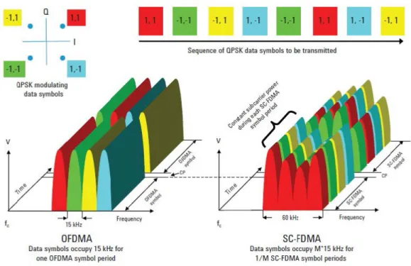
Fig. 2.1: Representation of a OFDMA transmission versus a SC-FDMA transmission. ... 6
Fig. 2.2: OFDM Spectrum. ... 7
Fig. 2.3: Comparison of the bandwith use between a FDM system (a) and a OFDM
system (b) and the respectively savings. ... 8
Fig. 2.4: OFDM block diagram. ... 9
Fig. 2.5: Duration of OFDM symbols. ... 9
Fig. 2.6: OFDM Transmission Scheme (Modulator). ... 12
Fig. 2.7: OFDM Receiver Side (Demodulator). ... 12
Fig. 2.8: Multipath Propagation Scheme. ... 13
Fig. 2.9: Guard Interval between symbols, as know as Cyclic Prefix. ... 14
Fig. 2.10: Data Scheme without CP. ... 14
Fig. 2.11: Data Scheme with CP. ... 15
Fig. 2.12: OFDM transmiter and receiver. ... 16
Fig. 2.13: OFDM versus OFDMA transmission schemes. ... 17
Fig. 2.14: OFDMA, used in the DL Multiple Acess. ... 17
Fig. 2.15: Single-Carrier Modulation (used in SC-FDE) vs Multi-Carrier Modulation
(applied in OFDM). ... 19
Fig. 2.16: SC-FDE block diagram. ... 20
Fig. 2.17: a) OFDM versus b) SC-FDE frequency allocation. ... 21
Fig. 2.18: SC-FDE (SC-FDMA), used in the UL Multiple Acess. ... 21
Fig. 2.19: SC-FDMA versus OFDMA blocks chain. ... 22
Fig. 2.20: IFFT block position in OFDM vs SC-FDE. ... 23
Fig. 3.1: Different types of Diversity Techniques. ... 25
Fig. 3.2: Types of Spatial Diversity. ... 26
Fig. 3.3: Types of Spatial Diversity in Transmission and Reception. ... 28
Fig. 3.4: Diversity vs Multiplexing in MIMO systems. ... 29
Fig. 3.5: TDD system Protocol for Massive-MIMO. ... 30
Fig. 3.6: SC-FDE transmission structure. ... 31
Fig. 3.7: Multi- user UL in Massive-MIMO. ... 31
Fig. 3.8: Transmitter side. ... 32
Fig. 3.9: Receiver side. ... 33
Fig. 4.1: Frequency Domain Equalization. ... 35
Fig. 4.2: MRC blocks diagram. ... 37
Fig. 4.3: EGC equalizer diagram. ... 38
Fig. 4.4: IB-DFE equalizer diagram. ... 39
Fig. 5.1: Massive-MIMO Scheme, receiver side detailed. ... 47
Fig. 5.2: Simplified block diagram for illustration of incorporating IQ imbalance at both
the transmitter and the receiver. ... 49
xiv
Fig. 5.1: Analog to Digital Conversion. ... 50
Fig. 5.4: Example of a Flash ADC, with threshold V
ref. ... 50
Fig. 5.5: Priority Encoder working example. ... 51
Fig. 5.6: Quantization process. ... 52
which can be translated to: ... 53
Fig. 5.7: SQNR (dB) as a function of the normalized clipping level employing different
number of resolution bits. ... 56
Fig. 6.1: Iterations Effect EGC+IBDFE (T=4, R=8). ... 60
Fig. 6.2: Iterations Effect EGC+IBDFE (T=4, R=16). ... 61
Fig. 6.3: Iterations Effect EGC+IBDFE (T=4, R=64). ... 61
Fig. 6.4: Iterations Effect MRC+IBDFE (T=4, R=8). ... 62
Fig. 6.5: Iterations Effect MRC+IBDFE (T=4, R=16). ... 62
Fig. 6.6: Iterations Effect MRC+IBDFE (T=4, R=32). ... 63
Fig. 6.7: Iterations Effect MRC+IBDFE (T=4, R=64). ... 63
Fig. 6.8: Iterations Effect, Comparison between Receivers at low Ratio (T=4, R=8). ... 64
Fig. 6.9: Iterations Effect, Comparison between Receivers at high Ratio (T=4, R=64). .. 64
Fig. 6.10: Constant Ratio (T=4, R=8). ... 65
Fig. 6.11: Constant Ratio (T=8, R=16). ... 65
Fig. 6.12: Constant Ratio, (T=16, R=32). ... 66
Fig. 6.13: Ratio 1 (T=4, R=4). ... 67
Fig. 6.14: Ratio 2 (T=4, R=8). ... 67
Fig. 6.15: Ratio 4 (T=4, R=16). ... 67
Fig. 6.16: Ratio 8 (T=4, R=32). ... 68
Fig. 6.17: Ratio 16 (T=4, R=64). ... 68
Fig. 6.18: Increasing T, Decreasing Ratio (T=4, R=64). ... 69
Fig. 6.19: Increasing T, Decreasing Ratio (T=8, R=64). ... 69
Fig. 6.20: Increasing T, Decreasing Ratio (T=16, R=64). ... 69
Fig. 6.21: System performance without ADCs vs with 1-bit ADCs, (T=4, R=8). ... 71
Fig. 6.22: System performance without ADCs vs with 2-bit ADCs, (T=4, R=8). ... 72
Fig. 6.23: System performance without ADCs vs with 6-bit ADCs, (T=4, R=8). ... 72
Fig. 6.24: System performance without ADCs vs with 1-bit ADCs, 2-bit ADCs and 3-bit
ADCs for (T=4, R=16). ... 73
Fig. 6.25: System performance without ADCs vs with 3-bit ADCs, (T=4, R=32). ... 74
Fig. 6.26: System performance without ADCs vs with 3-bit ADCs, (T=4, R=64). ... 74
Fig. 6.27: System performance without ADCs vs with 6-bit ADCs, (T=4, R=64). ... 75
Fig. 6.28: Iterative MRC vs Iterative EGC (without ADCs vs with 1-bit ADCs), (T=4, R=16
/ R=64). ... 75
Fig. 6.29: ZF vs Conventional-IBDFE (without ADCs vs with 1-bit ADCs), (T=4, R=16 /
R=64). ... 76
Fig. 6.30: Impact of Antennas in the performance of a NL System with 1-bit ADCs, for
all the equalization techniques (T=4 / T=40, R=64). ... 77
Fig. 6.31: Impact of Antennas in the performance of a NL System with 1-bit ADCs, for
all the equalization techniques (T=16, T=40, R=128). ... 77
Fig. 6.32: ZF vs CIBDFE Performances in NL System with 1-bit ADCs vs 6-bits ADCs, for
(T=4, increasing R). ... 78
xv
Fig. 6.33: Iterative MRC vs Iterative EGC Performances in NL System with 1-bit ADCs vs
6-bit ADCs, (T=4, increasing R). ... 78
Fig. 6.34: Optimum Normalized Clipping Level for a certain number of Bits of
Resolution. ... 80
Fig. 6.35: ADCs resolution impact in the performance of NL system with ZF vs CIBDFE,
for (T=4, R=32 and T=4, R=64). ... 81
Fig. 6.36: ADCs resolution impact in the performance of NL system with Iterative MRC
vs Iterative EGC, for (T=4, R=32 and T=4, R=64). ... 81
Fig. 6.37: Clipping impact in the performance of NL system with Iterative MRC vs
Iterative EGC, for different resolutions (b=1, b=3, b=5, b=10) considering (T=4 and
R=140). ... 82
Fig. 6.38: Clipping impact in the performance of NL system with ZF vs CIBDFE, for
different resolutions (b=1, b=3, b=5, b=10) considering (T=4 and R=140). ... 83
xvii
Acronyms
1G - First Generation of Mobile Communications
2G - Second Generation of Mobile Communications
3G - Third Generation of Mobile Communications
4-PSK - Quadrature Phase Shift Keying
4G - Fourth Generation of Mobile Communications
5G - Fifth Generation of Mobile Communications
8-PSK - Octogonal Phase Shift Keying
ADC - Analog to Digital Converter
ADSL - Assymetric Digital Subscriber Line
AMPS - Mobile Phone System
AWGN - Additive White Gaussian Noise
BER - Bit Error Rate
BS - Base Station
CDMA - Code Division Multiple Acess
CEPT - Confederation of European Posts and Telecommunications
CP - Cyclic Prefix
CSI - Channel State Information
DAC - Digital to Analog Converter
DFE - Decision Feedback Equalization
DFT - Discrete Fourier Transform
DL - Downlink
DS - Delay Spread
EDGE - Enhanced Data Rates for GSM Evolution
EGC - Equal Gain Combining
FD - Frequency Domain
FDD - Frequency Division Duplex
FDE - Frequency Domain Equalization
xviii
FDM - Frequency Division Multiplexing
FDMA - Frequency Division Multiple Acess
FFT - Fast Fourier Transform
GMSK - Gaussian Minimum Shift Keying
GSM - Groupe Speciale Mobile
IB-DFE - Iterative Block with Frequency Domain Equalization
ICI - Inter Channel Interference
IDFT - Inverse Discrete Fourier Transform
IFFT - Inverse Fast Fourier Transform
IID - Independent Identically Distribution
IS-95 - Interim Standard 95
ISDN - Integrated Services Digital Network
ISI - Inter Symbol Interference
IUI - Inter User Interference
IoT - Internet of Things
IP - Internet Protocol
LLR - Log Likelihood Ratio
LTE - Long Term Evolution
MFB - Matched Filter Bound
MIMO - Multiple Input Multiple Output
MISO - Multiple Input Single Output
MLSE - Maximum Likelihood Sequence Estimation
MMSE - Minimum Mean Squared Error
MRC - Maximum Ratio Combining
MSB - Most Significant Bit
MSE - Mean Squared Error
MT - Mobile Terminal
MU - Multi-User
MU - MIMO - Multi User Multiple Input Multiple Output
NSR - Noise to Signal Ratio
OFDM - Orthogonal Frequency Division Multiplexing
OFDMA - Orthogonal Frequency Division Multiple Access
PA - Power Amplifier
xix
PAPR - Peak-to-Average Power Ratio
QAM - Quadrature Amplitude Modulation
QPSK - Quadrature Phase Shift Keying
QoS - Quality of Service
R - Number of receivers
RF - Radio Frequency
Rx - Receiver Antennas
SC - Single Carrier
SC-FDE - Single Carrier with Frequency Domain Equalization
SC-FDMA - Single Carrier Frequency Domain Multiple Access
SIMO - Single Input Multiple Output
SINR - Signal to Interference and Noise Ratio
SISO - Single Input Single Output
SNR - Signal-to-Noise Ratio
SQNR - Signal-to-Quantization Noise Ratio
SU - Single-User
T - Number of Transmitters
TD - Time Domain
TDD - Time Division Duplex
Tx - Transmitter Antennas
UL - Uplink
UMTS - Universal Mobile Telecommunications System
WCDMA - Wide-Band Code-Division Multiple Acess
WLAN - Wireless Local Area Network
1
1. Introduction
1.1
Context and Motivation
Over the past generations, there has been a significant evolution in mobile communica-tions and in the transmission techniques applied in each of these generacommunica-tions. The block transmis-sion techniques, as Orthogonal Frequency Divitransmis-sion Multiplexing (OFDM) and the Single Carrier with Frequency Domain Equalization (SC-FDE), have been employed regularly in scenarios whose transmission channel is severely time-dispersive. The implementation of such techniques have been combined with schemes where multiple antennas are used in the transmitter side and in the receiver side. These Multiple Input Multiple Output (MIMO) systems were developed to perform higher rates and overcome the need for fast and reliable communication links. These models become especially interesting due to the fact that there is an exponential increase in the speed of transmission and in the capacity of telecommunications systems, a characteristic that is more and more requested due to the current level of technological evolution to which electronic devices are subject daily, as well as the applications that are proving to be more and more expen-sive in the processing resources. In today's world, the number of devices that are connectable to the communication networks in operation, increases exponentially day by day. The need for high data transmission rates, has also increased the impact of multipath propagation effect as well as the Inter Symbol Interference (ISI), facts which make the development of more evolved equali-zation methods necessary. Before 1990s, the multipath propagation effect has been considered one of the main obstacles to achieve higher transmission rates. This undesirable, but natural effect, occurs due to the different delays originated with the severall different reflections and interfer-ences in the propagation of the signal through out the transmission channel. The different delays, due to the obstacles and interferences, provoke the so called ISI. Expressing this effect in the Time Domain (TD), we can consider that the Delay Spread (DS) is the time measure between the first and the last arriving signals. This measure is used to calculate the necessary Cyclic Prefix (CP), which consists in the guard time interval needed to be introduced between the transmitted symbols to prevent the occurrence of ISI. The use of the CP between the transmitted symbols leads to more limitations in the transmission data throughput [1]. The multipath propagation ef-fect, occurred in time domain, can lead the system to be sensitive to frequency selective fading, when the bandwidth of the signal is larger than the coherence bandwidth.
2
In this thesis we will focus on the Uplink (UL) transmission. It is of major importance to take into account the energy efficiency in the transmission process, since it is a critical aspect in cell-phones, the onwards called Mobile Terminals (MT). Taking this fact into account, although usual because of his great performances, the OFDM modulation technique is not suitable to be used in the UL direction, due to its high complex envelope fluctuations that lead to a high Peak to Average Power Ratio (PAPR) [2]. Therefore, the SC-FDE, which avoids the undesirable PAPR, surges as an option to the UL since it has similar results to OFDM [3].
The next generation of wireless communication systems is expected to reach even larger speeds and capacity of users, as well as it is intended to perform transmissions with less latency.
In order to achieve these 5th Generation (5G) objectives, the Massive Multiple Input Multiple
Output (Massive-MIMO) architecture is assumed to be the ideal strategy, already with some proven results of great performances [4] [5]. The implementation of Massive-MIMO systems, where hundreds or even thousands of transmitter and receiving antennas are used, brings a lot of advantages but, despite that, it can also imply a greater complexity and become especially prob-lematic at the level of the receivers, during the signal equalization. In MIMO systems, during the equalization process, the operation of removing the channel effect, usually implies the inversion of the received data matrix. Thus, when the scale of a MIMO system is increased to a Massive-MIMO system, the channel matrices will be of a much larger size, so that the "normal" inversions in a MIMO system become something very undesirable and impractical in this type of system. The efficient equalization techniques such as Zero Forcing (ZF) and the Minimum Mean Squared Error (MMSE) become algorythms that are impractical in this scenarios. Thus, the need arises to develop distinct approaches that do not entail so much difficulty of execution with this evolved scenario. In this view, the use of low complexity receivers such as the Maximum Ratio Combining (MRC) and Equal Gain Combining (EGC) becomes as suitable options since they are simpler, even being these techniques less efficient than the previously refered. These equalization methods avoid carrying out these matrix inversion operations which entail enormous processing costs. Then, this thesis focus in the application of these low complexity equalization techniques, coupled with the association of iterative feedback schemes which are good in deal with the ISI and Inter User Interference (IUI). The Iterative Block Decision Feedback Equalization (IBDFE) works in an iterative fashion that leads to an enhancement in the performance as the iterations number increases. The objective is to put the capabilities of the IBDFE together with the low complexity algorythms MRC and EGC doing a joint solution. Since this thesis is focused in the receiver side, it also becomes pertinent to approach the Analog to Digital Converters (ADCs) that are needed in the receivers. These elements introduce Nonlinear Distortion Effects in the transmitted signals consonant the adopted number of bits of resolution. However, this distortion penalty tends to be
3
minimized when considering a scenario where we employ a much larger number of receiving antennas than the transmiting ones [6].
1.2
Objectives
In this document, a general approach will be made to the characteristics inherent to the mobile generations of the recent past and, in detail, a sequential description of transmission and reception technologies using the most advanced techniques and schemes.
We intend to provide a detailed description of possible approaches to implement the next generation of mobile communications: the so-called 5G. A distinct set of receiving techniques are described through a MIMO system. In evolving the scale of implementation of MIMO systems, it is pertinent to describe Massive-MIMO systems where there is a significant increase in the number of the used antennas. A detailed study will be conducted for a Massive-MIMO system considering the UL with the SC-FDE modulation. We will approach the main characteristics, advantages, disadvantages, potentialities and limitations of these models. The main objective is to compare the different types of receivers and understand the potential they have in the Massive-MIMO context. Emphasis is placed on low complexity receivers, namely the Maximum Ratio Combiner (MRC), and the Equal Gain Combiner (EGC). However, other algorithms, such as the Zero Forcing (ZF) and MMSE (Minimum-Square Error), as well as the Iterative Block Decision Feedback Equalizer (IB-DFE) based on the MMSE algorithm, are studied and analyzed because they are part of the implementation of a joint solution that can be applicable in perfect and imper-fect channels in Massive-MIMO scenarios. The combination of the low complexity algorithms with the iterative algorithms is addressed and is the main focus of this thesis. It is intended to make a study of a multi-user scenario in which each user only has one broadcast antenna, and the receiver is a Base Station (BS) with several receiving antennas. A performance and comparison evaluation will be done between the different receivers, contrasting different scenarios where the number of transmitter and receiver antennas that are employed is varied, as well as other factors inherent to the equalization algorithms themselves, such as the number of iterations used in the iterative equalization. Firstly, an analysis is made without the impact of non-linear elements, con-sidering only the signal sending, the modulation and the reception (where the equalization is done). Subsequently, it is considered the implementation of the ADCs in the receivers, elements which causes the introduction of non-linear distortion effects on the sent signals. The ADCs in-corporated in the receivers are of great importance in all data processing, and in this thesis, a greater emphasis will be given to the study of how standard saturation levels, as well as the num-ber of resolution bits of each element, may or may not influence the transmission performance of
4
signals that are received and need to be preprocessed prior to equalization. The study of impact of the nonlinearities on the transmitted signals is done in an analogous way to the study where they are not considered, i.e., they are considered in several types of scenario where the variation in the number of transmitter and receiver antennas is made. All the performance results are ob-tained through Monte-Carlo simulations, where we obtain a Bit Error Rate (BER) graphic in func-tion of the Signal-to-Noise Ratio (SNR). Finally, the objective is to show the importance that the high ratio between receiving and transmitting antennas has in the compensation of the negative effects of nonlinear distortion, thus showing that low-resolution ADCs are plausible for Massive-MIMO scenarios.
1.3
Organization
This thesis is organized in 8 different chapters. After this first chapter of
introduc-tion, the Chapter 2 contains the State of the Art where we approach the charachteristics
of the Mobile Networks. We emphasize the modulations used in the Long Term Evolution
(4G) that serves as a basis to the future 5G, namely the OFDM and the SC-FDE, the basis
to this thesis. In the Chapter 3 is described how important are the diversity techniques and
is also made a detail about the transmission and reception of signals in the broadband
wireless systems. The MIMO and Massive-MIMO technologies are conveniently
ad-dressed, since, this last, is the main theme of work in this thesis. In Chapter 4 are described
the proposed equalization techniques, namely the low complexity algorithms, of major
importance to this work, associated with the iterative equalization schemes. In chapter 5
we present the Non-linear effects and the hardware elements, in this case the ADCs,
which are known by provoke a negative impact in the systems performance, with their
implementation made in the receivers. In the Chapter 6 we present all the performance
experimental results, firstly without considering the imposing of non-linear distortion
ef-fects, and after, with that imposition, doing a variation in severall parameters, as the
ber of antennas, number of iterations by the iterative equalization techniques, or the
num-ber of resolution bits and the clipping level effects. Finally, in Chapter 7 we present the
conclusions about this thesis and the possible future work to explore in this addressed
matter.
5
2. State of the Art
2.1 Fourth Generation of Mobile Communications (LTE) - 4G
The 4G appears on scene presenting herself as a set of standard measures and is proposed with very specific objectives to succeed the 3G. The Long Term Evolution (LTE) by itself sug-gests that the goals to be achieved in this generation will not be achieved from the start in a single time, but gradually, rather the years ahead and the development of new emerging technologies. LTE has come about because of the natural, fast and constantly revolutionary evolution of tech-nology. Applications designed for mobile devices are increasingly reminiscent of data resources, and users are increasingly craving for faster and better Internet services to respond to those same applications. In this way, mobile communications systems have had to adapt to developments in the technological world in a way that can respond effectively to this huge demand of data-rates. The new 4G system was proposed to evolve the existing Universal Mobile Telecommunications System (UMTS) network, allowing communications over the Internet through the Internet Proto-col (IP), as already existing in previous generations, although in a much faster, reliable and secure way. Services such as video chat, streaming, high-definition television on the mobile phone and the many other services available on the Internet should also be achieved on mobile devices. Some of the proposed objectives for the 4G were:
- Enhancement of the dynamic capacity of the system, allowing the allocation of more users simultaneously in a cell;
- Coexistence with existing systems, i.e., combining narrow band systems (200 kHz GSM) and broadband systems (5MHz Wide-Band Code-Division Multiple Acess (WCDMA));
- Reduce the latency between communications, providing a faster response in the com-munication between users and the network;
- Increase or even attempt to maximize spectral efficiency;
- Flexibility and dynamism in the assignment of the frequency band available according to the services that are required by the users at a given moment;
- A fully IP network, with packet-only switching and thus more simplified;
- Optimization of the power efficiency of the mobile terminals with consequent saving in terms of energy levels of the batteries;
6
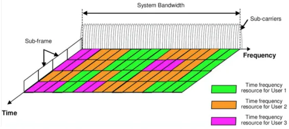
The development of the LTE system began with the approach taken in a 3rd Generation Partnership Project (3GPP) study in 2004 in Canada. This joint collaboration of the mobile com-munications industry organizes and manages the development of standards for mobile communi-cations systems. The new system should have a distinct and more comprehensive / manipulable architecture with the existing radio Technologies, in terms of multiple access and multiplexing. The evolution of WCDMA was not enough, due to the large bandwidth that would be used and the complexity that this would entail, so it became imperative to design a whole new system [7]. Thus, two new technologies emerge to the sceene and would come to be implemented; the first one for Downlink (DL), the Orthogonal Frequency Division Multiple Access (OFDMA), based on OFDM and the another one to do the UL transmission, namely the Single Carrier Fre-quency Domain Multiple Access (SC-FDMA), based on SC-FDE. The terms Multiple Access arise in the LTE because of the strategy adopted to increase system capacity by multiplexing more users by dividing the frequency assignment (groups of frequency bandwidths) in the case of SC-FDE and individual sub-carriers in the case of OFDM, respectively at different time intervals and in different channels, thus giving a more dynamic and maximized use of the system. OFDM and SC-FDE are the “single user” or the “basis” versions.
Fig. 2.1: Representation of a OFDMA transmission versus a SC-FDMA transmission.
7
2.2 OFDM - Orthogonal Frequency Division Multiplexing
The OFDM consists of a frequency division multiplexing technique in which the spec-trum of the subcarriers frequencies is partially overlapping one another, rather than being posi-tioned consecutively, side by side (parallel) to one another, as in Frequency Division Multiple Acess (FDMA). The main objective with this technique of overlapping carrier waves is to save or to take the maximum advantage of the frequencies of the available bandwidth. Although this overlap occurs, the subchannels are associated with frequencies that are orthogonal to each other, thus making it possible to make a complete and efficient recovery of the signal that was sent, and that finally reaches the receiver, without compromising the quality of the signal.
Fig. 2.2: OFDM Spectrum.
(Source: [9])
The orthogonality between the different N subcarriers corresponding to a sent signal is achieved and guaranteed by the emission of pulses of rectangular shape (binary digital transmis-sion). Thus, the discrete time domain signal is converted to the frequency domain by the Fourier Transform operation, where the N generated subcarrier waves are to be viewed individually as Sinc signals whose central frequency corresponds to the frequency of the corresponding
subcar-rier and whose zeros of those Sinc signals are spaced apart by a factor of !
"# (where K is an integer).
According to the mathematical properties of the frequency domain analysis (Fourier Analysis), it is crucial to ensure that the simultaneous spacing between all N subcarriers corresponds to a factor of "$
# (𝑇& being the value corresponding to the time of symbol duration or interval time between
symbols) so that there may be no overlapping of the center frequencies of each carrier with the adjacent carriers. The subcarrier frequencies are equally spaced and hence the subcarriers sepa-ration is constant. Thus, without overlaps, it is possible to guarantee the orthogonality and conse-quently it is possible to recover the signal at the receiver when demodulating and equalizing in the frequency domain.
8
Furthermore, one of the big advantages of this type of scheme is that it allows to obtain notable gains in terms of saving the use of the available spectrum (a scarce and important re-source) when compared with simple Frequency Division Multiplexing (FDM) systems, that is, this type of application becomes more efficient at the spectral level because of the partial over-lapping between subcarriers. [10]
Fig. 2.3: Comparison of the bandwith use between a FDM system (a) and a OFDM system (b) and the respectively savings.
(Source: [11])
OFDM is the technique applied in 4G/LTE, mainly in the DL connection, due to severall advantages it presents. OFDM techniques are intended to be a way of transmission data-streams of a single user in all the available subcarriers in a certain moment or through-out consecutive time periods. It is possible for other users to transmit simultaneously (i.e., during the same symbol times) but on different sub-carriers or in different subcarrier sets (so, in parallel). The simplest situation is when all the available subcarriers are allocated to a user for all of the time.
The data symbols are transmitted independently over many closely spaced orthogonal subcarriers making use of Quadrature Phase Shift Keying (QPSK) or Quadrature Amplitude Mod-ulation (QAM) as 4-QAM (2 bits per time-symbol), 16-QAM (4 bits per time-symbol) or 64-QAM (6 bits per time-symbol) Modulations, depending on the quality conditions of the
transmis-sion channel. The combination of a time-slot (𝑇' time period) with a certain subcarrier or set of
subcarriers, corresponds to a source where each symbol (the usefull part) is modulated in a certain modulation. Finally, gathering everything, the modulated waveform is composed of N orthogonal subcarriers with each narrowband subcarrier.
9
Fig. 2.4: OFDM block diagram.
(Source: [12])
The M-point time-domain blocks obtained from the IFFT (after the serial to parallel con-version of all the modulated symbols) are then serialized to create a time-domain signal after the add of CP. The CP is added to each symbol to minimize the ISI caused by the time dispersive
channels (due to the delay spread created by the multipath propagation). The CP duration (𝑇2)
should be sufficient to cover the delay spread energy of a radio channel impulse response. After
the insertion of the CP, the OFDM symbol duration (𝑇&) should be:
𝑇&= 𝑇2+ 𝑇'
(1)
As it can be seen in the following figure:
Fig. 2.5: Duration of OFDM symbols.
10
2.2.1 Continuous-Time Implementation
A modulated signal in OFDM consists of a sequence of data blocks whose mathematical expression, representative of this signal in the time domain, is given by the following equation in the complex form:
𝑠 𝑡 = 𝑆8,:𝑔:(𝑡 − 𝑛𝑇&) ?@$ :AB C 8A@C (2) where: 𝑔: 𝑡 = 𝑒 EFGHI, 𝑡 𝜖 0, 𝑇 & 0, 𝑜𝑡ℎ𝑒𝑟𝑤𝑖𝑠𝑒 (3) and: 𝑓: = 𝑓B+ 𝑘×1 𝑇& 𝑤𝑖𝑡ℎ 𝑘 = 0,1,2, … , 𝑁 − 1 (4)
where 𝑆8,: is the symbol that is transmitted in the 𝑛IX time slot by the 𝑘IX subcarrier.
𝑆8,: is a complex number such that 𝑆8,: = 𝑎8,: ± 𝑗𝑏8,: is associated with a point of the
considered constellation (QAM, QPSK, etc.).
𝑇& is the variable which represents the symbol time interval. 𝑁 is the variable representing
the number of subcarriers used for transmission, while 𝑓: is the frequency of the 𝑘IX subcarrier,
where 𝑓B is the frequency value of the first subcarrier.
Thus, the term in brackets in (2) corresponds to the OFDM block sent in the 𝑛IX interval,
represented by 𝑆8 𝑡 .
The signal 𝑆8 𝑡 which is actually transmitted corresponds to the real part, described by:
𝑆8 𝑡 = 𝑅𝑒[ 𝑆8,:𝑔:(𝑡 − 𝑛𝑇&)
?@$
:AB
] (5)
Taking into account (2) comes:
𝑆8 𝑡 = 𝑅𝑒[ 𝑆8,:
?@$
:AB
𝑒E`GHI] (6)
decomposing 𝑒E`GHI, arises:
𝑆8 𝑡 = {𝑎8,:cos 2𝜋𝑓:𝑡 − 𝑏8,:sin 2𝜋𝑓:𝑡}
?@$
:AB
, 𝑡 ∈ [𝑛𝑇&, (𝑛 + 1) 𝑇&]. (7)
Thus the OFDM block appears as a sequence of 𝑆8(𝑡) blocks:
𝑠 𝑡 = 𝑆8(𝑡)
C
8A@C
(8) The demodulation of the signal is made based on the orthogonality present in the subcarriers,
11
through the following operation:
𝑔: 𝑡
"#
𝑔:i∗ 𝑡 𝑑𝑡 = 𝑇
&𝛿(𝑘 − 𝑘′) (9)
And the received signal is then obtained by the following relation: 𝑆8,:= (8n$)"#𝑠 𝑡 𝑔:i∗(𝑡)
8"# 𝑑𝑡 (10)
2.2.2 Discrete-Time Implementation
The implementation of OFDM systems in the Continuous-Time domain becomes impracticable due to the extreme complexity that this entails, thus giving rise to the implementation of this system in the Discrete-Time domain as the viable alternative. This implementation is based on the operation of the Fast Fourier Transform (FFT).
By sampling the signal to be transmitted in OFDM [described in (2) and (5)], at a
frequency N times greater than the symbol rate of the "$
# subcarriers and assuming 𝑓B = 0, we
obtain the following:
𝑆8 𝑚 = 𝑆8,:𝑔: 𝑡 − 𝑛𝑇& , 𝑡 = (𝑛 + 𝑚 𝑁) 𝑇& 𝑎𝑛𝑑 𝑚 = 0,1, . . . , 𝑁 − 1. ?@$ :AB (11) By doing the substitution of (3), appears the following:
𝑆8 𝑡 = 𝑆8,:𝑒E`GHI= 𝑁. 𝐼𝐷𝐹𝑇{𝑆8,:}
?@$
:AB
(12)
Thus, it is possible to generate the signal 𝑆8(𝑡) equivalent to a block of the baseband
signal 𝑠(𝑡) from its samples, since these correspond to the IDFT of the complex numbers 𝑆8,:
less than one factor N-scale. For this to be possible, the sampling frequency ?s
"# must be equal to
or greater than the Nyquist frequency.
Finally, the demodulation of the signal is performed through the Discrete Fourier
Transform (DFT), obtaining 𝑆8,:.
The exemplary scheme of modulation and demodulation of an OFDM system with QPSK/4-QAM can be seen in the following block diagrams:
12
Fig. 2.6: OFDM Transmission Scheme (Modulator).
(Source: [14])
It is possible to verify that to implement this type of transmission structure it is necessary to make use of N different oscillators, each one of them associated to each one of the different subcarriers, that is, for N different frequencies, N different oscillators must exist, as well as N analog filters (which from the point of view of implementation costs can be very expensive).
Fig. 2.7: OFDM Receiver Side (Demodulator).
(Source: [14])
2.2.3 On the Reception of Data Streams
An OFDM-modulated signal can traverse a highly time-dispersive (high Delay Spread) channel ℎ(𝑡), thus the transmitted signal can be affected by random noise 𝑛(𝑡). In this situation, the received signal 𝑦(𝑡), is given by:
𝑦 𝑡 = 𝑠 𝑡 ∗ ℎ 𝑡 + 𝑛 𝑡 (13)
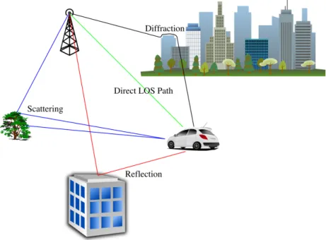
In most situations, the channel used to transmit the signal is highly Delay-Dispersive because of the multipath propagation phenomenon that triggers a sequence of extraordinary elements affecting the original transmitted signals. The multipath propagation yields signal paths of different paths with different times of arrival at the receiver.
13
Fig. 2.8: Multipath Propagation Scheme.
(Source: [15])
This situation is very problematic because, due to it, there is the so-called Inter-Symbol Interference (ISI) phenomenon and, in the case where the channel is heavily delay-dispersive, this phenomenon can affect the adjacent data blocks between each other. That is, the consecutive symbols from a data-stream sent by a user, run the risk of overlapping each other upon arrival at the receiver.
Considering the discrete time domain, the channel can be characterized by the discrete time impulse response ℎ[𝑖], 𝑤𝑖𝑡ℎ 𝑖 = 0, . . . , 𝐿, where 𝐿 is the value corresponding to the Channel Delay Spread, i.e., the maximum value of delay imposed by the channel on the received signal, whereby the following equations can be written:
𝑦 𝑚 = 𝑠 𝑚 ∗ ℎ 𝑚 + 𝑛(𝑚) (14)
𝑦 𝑚 = ℎ 𝑖 . 𝑠 𝑚 − 𝑖 + 𝑛[𝑚]
v
wAB
(15) From (15) it can be concluded that the response at any instant m depends on m-i previous values, which, in turn, can give rise to the ISI phenomenon.
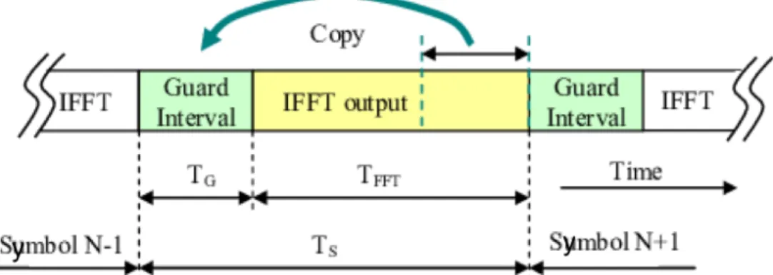
One way to combat this problem is to basically copy a set of samples from the final part of the OFDM block and enter them at the beginning of the block, that is, to repeat them. These samples are repeated in the time domain and have, at most, a size equal to the maximum delay spread of the channel.
The orthogonality between subcarriers is maintained, and this set of data which is repeated at the beginning of the OFDM block is the CP, as illustrated in the following figure:
14
Fig. 2.9: Guard Interval between symbols, as know as Cyclic Prefix.
(Source: [16])
This highly efficient process consists of copying symbols from the end of the OFDM block and inserting these same symbols before the beginning of the block, which in a certain way will be a repetition at the beginning of the data block.
The CP must have a length (duration) greater than or equal to the channel's maximum delay spread.
The introduction of the CP is important for bridging the negative consequences, namely the ISI due to the multipath effect, which affect the signal processing at the receiver. These phenomenon, that occurs in multipath propagation and that cause delays in arriving at the receiver, are, in particular: the phenomenon of reflection, diffraction and dispersion of the signal in the various obstacles of the channel.
Below is possible to identify the situation where there is not implemented the CP and the consequent occurrence of ISI in the receiver:
Fig. 2.10: Data Scheme without CP.
15
However, as we can see, with the insertion of the CP between the transmited symbols, we obtain the following structure where the ISI is totally avoided:
Fig. 2.11: Data Scheme with CP.
(Source: [17])
The CP, when copied from the final part of the block and introduced at its beginning, causes the symbol to "close itself", that is, the symbol that was previously a discrete linear convolution, is now seen as a circular convolution (also discrete in time).
Thus, the received data can be analyzed as a result of a circular convolution between the channel impulse response and the data block, together with the addition of the noise interference. At the receiver side, it is then possible and feasible to perform the equalization in the frequency domain. In this way, the received signal can be represented as follows:
𝑦 𝑚 = 𝑠 𝑚 ∗ ℎ 𝑚 + 𝑛 𝑚 = 𝐼𝐷𝐹𝑇 𝑋8,: ⊗ ℎ 𝑚 + 𝑛 𝑚 (16)
Upon receipt of this signal, the DFT is applied, passing the TD signal to the FD:
𝑌8,: = 𝐷𝐹𝑇 𝑦 𝑚 = 𝐷𝐹𝑇 𝐼𝐷𝐹𝑇 𝑋8,: ⊗ ℎ 𝑚 + 𝑛 𝑚 (17) ⇔ 𝑌8,: = 𝐷𝐹𝑇 𝑦 𝑚 = 𝑆8,: . (𝐷𝐹𝑇 ℎ 𝑚 ) + 𝐷𝐹𝑇 𝑛 𝑚 (18) ⇔ 𝑌8,: = 𝑆8,: . 𝐻: + 𝑁: (19) with: 𝐻: = 𝐷𝐹𝑇 (ℎ[𝑚]) (20) and 𝑁: = 𝐷𝐹𝑇 (𝑛[𝑚]) (21)
In fact, (20) corresponds to the channel frequency response function, sampled at the
fre-quency of the 𝑘IX sub-carrier.
The equation (21) corresponds to the noise that is added in the transmission and which obeys a Gaussian distribution with zero mean.
16
also be concluded that the orthogonality between the sub-carriers remains, even after the intro-duction of the channel effect.
Upon arrival of the signal to the receiver, it becomes necessary to do the equalization of the signal, i.e., to remove the effect of the channel on the signal that was originally transmitted to obtain the transmitted data. This equalization process will be addressed later in (𝑠𝑒𝑐𝑡𝑖𝑜𝑛 4).
The 𝐹𝑖𝑔. 2.12 shows an OFDM system diagram, making emphasis on the transmitter and receiver. In this systems, each user transmits symbols in the time-domain and in a ‘parallel scheme’, that is, each user has a certain portion of the total existing bandwidth. For the sake of simplicity and to give an example, let us consider that each user has one dedicated frequency. This implies that, for each one of the users, the transmission of their respective data-streams is made only at one frequency allocated to each one of them and in each time period (sequence of time-slots). This division of the bandwidth results in an increase in the duration of the time-sym-bol for each of the different flows of data (for each user) in order to compensate the ‘limitation’ of frequencies allocation that was made to each user. The available bandwidth to use is given by:
𝐵𝑎𝑛𝑑𝑊𝑖𝑑𝑡ℎ = 1
𝑇& (22)
Fig. 2.12: OFDM transmiter and receiver.
(Source: [18])
With the symbol duration increased in this type of parallel transmission, when compared to a serial transmission, it is verified that the OFDM system is more robust to the multipath pro-pagation effect. Then, with the insertion of the CP, the hypothetical occurrence of ISI is decreased. The Multiple Acess Scheme applying the OFDM basics is called Orthogonal Frequency Division Multiple Acess (OFDMA) and it provides a better usage of the Frequency and Time
17
availabilities or accessibility. Despite OFDM can be applied in a multi-user situation, the OFDMA is more dedicated and suitable for that type of scenario due to a better management of the demand by the users, as represented in the 𝐹𝑖𝑔. 2.13 and 𝐹𝑖𝑔. 2.14.
Fig. 2.13: OFDM versus OFDMA transmission schemes.
(Source: [19])
The OFDMA is largely used in the most recent Mobile Communications, as LTE/4G, because of their great dynamism in the resources management and consequent better capacity.
Fig. 2.14: OFDMA, used in the DL Multiple Acess.
(Source: [20])
The LTE architecture and system itself focuses on energy efficiency and thus implies some requirements in its operation by the MTs. The transmission power of the mobile phones must be below certain limits to avoid the high energy consumption (due to signal amplification). This translates into the, as small as possible, Peak to Average Power Ratio (PAPR) values:
𝑃𝐴𝑃𝑅 =𝑃𝑂𝑊𝐸𝑅𝑎𝑣𝑒𝑟𝑎𝑔𝑒
18
where POWERpeak corresponds to the peak power of the symbol and the POWERaverage corre-sponds to the average power of all transmitted blocks of symbols. This ratio is usually high in OFDM/OFDMA, since the complex symbols associated with each subcarrier are distributed ac-cording to an Independent Identically Distribution (IID), and in addition being the IDFT operation associated with each one of the subcarriers independently. This is a linear transformation process on a large number of complex symbols modulated in QAM (Quadrature Amplitude Modulation) according to an IID. This makes the amplitude of the symbols, that are transmitted, depend di-rectly on the constellation points of the modulation scheme concerned. Thus, and considering the Central Limit Theorem, an OFDM-based signal, in TD, can be approximated by a Gaussian dis-tribution. This Gaussian distribution should show large amplitude variations for each of the trans-mitted symbols, thus causing a high PAPR (not desirable in MTs). This high PAPR has negative consequences since it causes high energy consumption due to the fluctuations of the signal enve-lope, thus forcing the electronic amplifiers of the MTs to work in non-linear (i.e., high load/satu-ration) regimes. In the DL, this type of situation is not so problematic since the transmitter is a BS, however, in the UL it is not desirable because the transmitter is a MT, which runs through batteries to be energetically powered. To overcome this critical drawback of OFDM, the next section approaches another similar technology to OFDM, whose’s better to deal with the UL transmissions of the MTs.
19
2.3 SC-FDE - Single Carrier with Frequency Domain Equalization
As was refered previously, the OFDM algorithm has some disadvantages to implement in the UL context. To avoid this problematic facts, a similar system to OFDM is presented which only differs in the way how the sequence of procedures is implemented, namely the IFFT block. All the negative aspects from the OFDM can be circumvented through a single-carrier approach called Single Carrier – Frequency Domain Equalization (SC-FDE) [21][22][23][24].
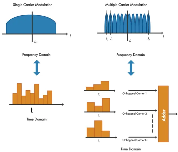
Fig. 2.15: Single-Carrier Modulation (used in SC-FDE) vs Multi-Carrier Modulation (applied in OFDM).
(Source: [25])
To avoid complexity in the architecture of the MTs, and a consequent saving of the use of batteries power, the SC-FDE algorithm works in a way where the transmited signals do not require the presence of a IFFT block in the UL transmitter device. In this UL focused context, the IFFT block is implemented in the SC-FDE receiver (the BS, where the power supply is not so critical) maintaining the complexity in the BS side. The difference between OFDM and SC-FDE
20
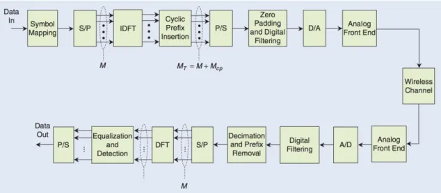
basically consists in the position of the IFFT block in the “procedures chain”. This method is highly efficient and maintains the same high performances of OFDM with the big advantage of low PAPR fluctuations [23]. The equalization in SC-FDE is also made in the frequency-domain.
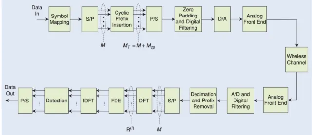
Fig. 2.16: SC-FDE block diagram.
(Source: [12])
While OFDM uses the different available subcarriers in the available bandwidth to trans-mit different simbols in different channels, the SC-FDE, in another way, uses all the available banwidth to a certain user to transmit blocks. So, instead of the OFDM where the different sym-bols (user data-stream) are transmited simultaneously (each symbol in a different sub-carrier through-out the time), the SC-FDE transmition scheme consists in transmit the symbols belonging to each user, each symbol in a time-slot and making use of all the available frequencies (a certain portion of band of the total bandwidth) in that period of time to each symbol transmission. In this way, all the available frequency resources, to one certain user, are dedicated to each symbol (or group of symbols) at a time-slot or sequence of time-slots, as we can see in 𝐹𝑖𝑔. 2.17.
21
Fig. 2.17: a) OFDM versus b) SC-FDE frequency allocation.
(Source: [26])
The SC-FDE is called Single Carrier Frequency Division Multiple Acess (SC-FDMA) in a multiple acess situation, where severall different users can be, respectivelly each one, allocated to transmit in a portion of the total available bandwidth. The SC-FDMA, as well as OFDMA, can be concerned as a more dynamic version of SC-FDE, as it is possible to observe in 𝐹𝑖𝑔. 2.18.
Fig. 2.18: SC-FDE (SC-FDMA), used in the UL Multiple Acess.
(Source: [20])
This modulation method avoids complexity, presents advantages and also has com-provedly equal or even better UL performances when compared with OFDM [12] reasons why it is used in the LTE/4G uplink. The absence of IFFT in the UL transmitter (MT) results in a less complex system, making the transmission mechanism much simpler and consequently saving power.
22
The SC-FDMA can be interpreted as a linearly precoded OFDMA scheme, in the sense
that it has an additional DFT processing step preceding the conventional OFDMA processing as
referred previously and as can be seen in 𝐹𝑖𝑔. 2.19.
Fig. 2.19: SC-FDMA versus OFDMA blocks chain.
(Source: [27])
This few diferences in the characteristics of both systems becomes particulary interesting to adapt the devices to be a tipical OFDM or a SC-FDE transmiter/receiver doing just the neces-sary change of the position of the IDFT block. The SC system transmits a single carrier, modu-lated at a high symbol rate (instead of OFDM with low symbol rate). The Frequency Domain Equalization (FDE) in a SC system is simply the FD analog of what is done by a conventional linear Time Domain Equalizer (TDE). For channels with severe Delay-Spread, the FDE is simpler than corresponding TDE, for the same reason that OFDM is simpler: the FFT operations and the simple channel inversion operation. The use of SC modulation and FDE by processing the FFT of the received signal has several attractive features, namely:
• The SC modulation has a reduced PAPR requirements when compared to OFDM, thereby al-lowing the use of less costly power amplifiers [22].
• The SC system performance with FDE is similar to OFDM performance, even for very long channel delay spread. The receiver complexity is similar to OFDM, proportional to the Logarithm of the multipath spread. Coding, while desirable, is not necessary for combating frequency selec-tivity, as it is in nonadaptive OFDM systems.
23
and its RF system linearity requirements are well known.
Both systems can be enhanced by coding (which is in fact required for OFDM systems), adaptive modulation and per space diversity. In addition, OFDM can be incorporate peak-to-av-erage reduction signal processing to partially (but not completely) alleviate its high sensitivity to power amplifier nonlinearities. SC-FDE can be enhanced by adding Decision Feedback Equali-zation (DFE) or Maximum Likelihood Sequence Estimation (MLSE) [28].
Comparable SC-FDE and OFDM systems have the same block length and CP lengths. Since their main hardware difference is the location of the IFFT, a modem can be converted as required to handle both OFDM and SC signals by switching the location of this block between the transmitter and receiver, as it can be seen in 𝐹𝑖𝑔. 2.20.
25
3. Schemes of Diversity, Transmission &
Recep-tion of Signals
3.1 Diversity Schemes to Improve the Bit Error Rates
As previously mentioned, the transmission of data through the air interface can be done through techniques with some degree of sophistication. These type of techniques for increasing the transmission gains aren’t itself enough to achieve the maximum benefit of what technology can offer nowadays. Then, it is possible to improve the Bit Error Rates (BER) of the data trans-missions between two points. In order to maximize the performance of telecommunication sys-tems, we take advantage of some techniques, the so-called diversity techniques. These techniques, whose are very important in achieving higher performances [29][30], can be combined with each other to approach even better results. They are represented in the 𝐹𝑖𝑔. 3.1:
Fig. 3.1: Different types of Diversity Techniques.
26
• Time Diversity - Corresponds to a transmission scheme, whose core business is related to the transmission of data in different time intervals (i.e.: consecutive), in order to combat the selectiv-ity in time by the physical environment where the transmission takes place (the channel). • Frequency Diversity - Consists in the transmission of a data block in a set of distinct frequencies within a certain bandwidth, in order to avoid channels that are selective in the frequency, that is, channels that cancel certain frequencies. This type of diversity technique only applies to non-flat-fading channels (non-frequency selective channels);
• Spatial Diversity - In this type of technique, several transmitting and receiving antennas are used to increase the multiplexing of communication "channels" between the transmitting and receiving ends, i.e.: achieving a greater amount of transmission possibilities and combinations between transmitting antennas and receiving antennas simultaneously, to transmit a given signal. This technique is very important in nowadays telecommunication systems, presenting a significant impact in the performance [32][33].
Fig. 3.2: Types of Spatial Diversity.
27
3.2 Transmission Schemes
3.2.1 MIMO – Multiple Input Multiple Output
Taking advantage of the spatial diversity, as we can see in 𝐹𝑖𝑔. 3.3, is possible to use
different types of schemes to transmit signals between an array of Transmitter Antennas (Tx) and an array of Receiver Antennas (Rx). The more multiplexing between Tx and Rx, more speed and reliability will be present in the transmission between the terminals (𝐹𝑖𝑔. 3.4). The most efficient scheme used in telecommunications is the MIMO where severall Tx transmit to severall Rx, thus resulting in a high performance communication system. This type of scheme can be designed to be used with 2x2, 2x4, 4x2, 4x4, 6x6, 6x4, or another type of structures, depending only in the available capacity to implement more or less Tx and Rx antennas. Over the last 20 years, MIMO technology has proven its excellent performance [35] and has been commonly integrated in sys-tems from 3G to LTE/4G with the aim of increase their capacity. LTE-Advanced (4.5G) and 5G are also two generations that use this kind of configurations to achieve higher rates of data trans-mission and to increase their capacities. The performance of telecommunication systems, in gen-eral, is proportional to the minimum number of necessary antennas used in the ‘Transmit/Receive’ relation. However, despite the milestones achieved to date with MIMO technology, according to
[1], the number of antennas currently employed in this type of configuration is still insufficient
to provide the desired rates for 5G. One can note that MIMO scenarios can be described also in two different ways, related to a Single-User (SU) transmission or to a Multi-User (MU) transmis-sion.
Nowadays, MIMO Techniques are used in the Wi-Fi networks as well as in the WLAN networks due to his efficiency in the presence of severall users. In MIMO schemes, the different Tx can be used to transmit Spacial Diversity (using the diferent Tx to transmit the same data package in simultaneous, resulting thus on a better system redundancy, and thus achieving better BERs, consequence of the higher reliability. By another way, MIMO systems are able to create a multiplexing scenario where each of the different Tx transmits different parts of the same data package with focus on the achievement of higher data rates.
28
Fig. 3.3: Types of Spatial Diversity in Transmission and Reception.
(Source: [36])
3.2.2 SIMO - Single Input Multiple Output
The Single Input Multiple Output (SIMO) model corresponds to a diversity reception system, in which the system has two or more Rx and only one Tx. This type of structure has its maximum performance when using combinatorial equalization techniques, that is, in order to use the information that reaches the receivers more efficiently.
3.2.3 MISO - Multiple Input Single Output
The Multiple Input Single Output (MISO) model, is a type of system that consists of transmit diversity, by implementing two or more Tx and using only one Rx. In this type of struc-ture, it is imperative to implement precoding algorithms to process the redundant information to be sent, so that there can be an efficient combination of the data at the equalization. Alamouti techniques are well suited for this type of application [37].
3.2.4 SISO - Single Input Single Output
The Single Input Single Output (SISO) model does not present any diversity. This type of configuration is the simplest one, but at the same time, the one who offers less advantages in