978-1-5386-3917-7/17/$31.00 ©2017 IEEE
Electric Vehicle Battery Charger Controlled by
Magnetic Core Reactor to
Wireless Power Transfer System
L.F. Romba, S.S. Valtchev, R. Melício
UNINOVA/CTS, Faculdade de Ciências e Tecnologia, Universidade Nova de Lisboa, Portugal
Departamento de Física, Escola de Ciências e Tecnologia, Universidade de Évora, Portugal
M.V. Mudrov, A.M. Ziuzev
Ural Federal University, Yekaterinburg, Russia([email protected]; [email protected]; [email protected]; [email protected];
Abstract—This paper presents a control process and
frequency adjustment based on the Magnetic Core Reactor prototype. For the past decades, there has been significant development in the technologies used in Wireless Power Transfer systems. In the Wireless Power Transfer systems it is essential that the operating frequency of the primary circuit be equal to the resonant frequency of the secondary circuit so there is the maximum energy transfer. The Magnetic Core Reactor allows controlling of the frequencies on both sides of the transmission and reception circuits. In addition, the assembly diagrams and test results are presented.
Keywords— Electric vehicles; magnetic core reactor; wireless power transfer; strongly coupled magnetic resonance.
I. INTRODUCTION
The Wireless Power Transfer (WPT) can be considered as an efficient power transmission process, from one point to another point through the vacuum or the atmosphere without electrical cables or any other conductive material [1-5].
The technologies applied in WPT systems are categorized as near-field, mid-range and far-field, which definition depends on the applied operating frequency and “antenna” size. The near-field system is used for very short distances, few millimeters, and employs the inductive power transfer technology. The mid-range system is used to cover distances between a few centimeters and a few meters, using the magnetic resonant technology. These two technologies are non-radiative. In contrast, the technology employed in far-field category system is radiative and requires special care in antenna alignments [1,2].
In the wireless power transfer via strongly coupled magnetic resonance the driving coils supply power to each resonant LC circuit (transmitter and receiver). The both resonant circuits are galvanically isolated from the other circuits but magnetically linked through the mutual inductance of the transmitter and the receiver coils [3,6]. The resonators should have high quality factor and the same resonant frequency.
However, the distance between the transmitter and the receiver can vary and misalignments may also occur. When this happens, the impedances of the resonators change. For to achieve a constant efficiency, the resonators frequency must be adjusted [2-10].
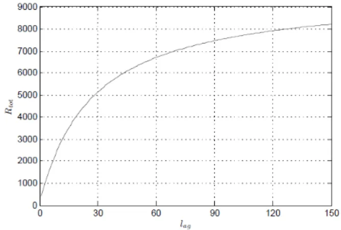
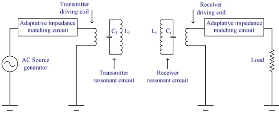
The magnetic coupling coefficient is directly proportional to the mutual induction between the transmitter and receiver coils. When the distance between the two coils changes, the mutual inductance is also changed, thus the coupling coefficient is consequently changed too [3,4]. When there is a misalignment or when the distance between the coils is changed the air gap ℓ varies [10,11-13]. This implies that magnetic reluctance ℜ is changed once it is directly proportional to ℓ . The Fig. 1 shows the relationship between the magnetic reluctance and the air gap. The layout of the wireless power transfer via strongly coupled magnetic resonance [14] is shown in Fig. 2.
Fig. 1. Variation of ℜ function of the ℓ .
The WPT systems, regardless of the frequency and power applied, are not excluded from the standards, regulations and norms dictated by various international organizations and regulations.
Fig. 2. Variation of ℜ function of the ℓ .
How the electromagnetic field affects the health of the human beings has been the subject of research and discussion in the most recent decades [15].
The mid-range WPT systems do not require a close proximity between the primary and secondary coils during power transmission. The use of this technology allows the power transmission to be extended, e.g. to a distance of two meters [4]. This distance that separates the coils do not allow any possibility for shielding of the entire volume filled by the magnetic field. By not having shield, the operation of the system may involve an increase of the emission levels, which can exceed the electromagnetic emission intensity limits and make dangerous the human exposure. This obliges to strictly comply with the approved standards [15].
The WPT process is essential for spread of EV. To achieve wireless charging, the WPT system must satisfy these three conditions: high efficiency, large air gaps and high power. The WPT via strongly magnetic resonance satisfy these three conditions [3,6].
The wireless EV charging system includes several stages. First the AC power from the grid is converted to a DC power. The DC power is converted to high-frequency AC to drive the transmitter coil. The transmitter resonant circuit should oscillate to the resonant frequency determined by LC set. The high-frequency current in transmitting coil generates an alternating magnetic field, which induces an AC voltage on receiver coil. At the last, the AC transferred power is rectified to charge the battery [6].
A. Magnetic Core Reactor
The magnetic core reactor (MCR) comprises one core and two windings. One of the windings is the AC component and the other winding is the DC control. Varying the DC current through the control winding vary the inductance and implicitly changed the inductive reactance this device. These devices work at the beginning of the knee of the saturation curve of the ferromagnetic core [3,4]. In this paper it is shown the use of this device for equalizing the frequencies of the transmitter and receiver in WPT system [4,7,8].
The most basic saturable reactor consists of a three-legged magnetic core, with coils wound on each leg. The core is shown in Fig. 3.
Fig. 3. Three-legged saturable core reactor.
The center leg normally is approximately twice as wide as the outer legs. Two coils having equal number of turns are wound on the outer legs. These are the AC coils or the load winding N . The coil on the middle leg normally has many more turns than the outer coils, serving as the control coil in DC or control winding N [12,13].
II. MODELING
The signal amount can be adjusted to the set point of the reactor flux by the amount of Δφ to any given point of the magnetic loop, in accordance with Faraday Law, given by:
dt E Nc c
=
Δφ 1 (1)
where Ec is the power from the source, Nc is the turns number of the control winding.
The coil inductance with the winding made on a magnetic core, using CGS units is given by:
H l S L N 10 9 2 4 − × = π μ (2)
where l is the length, N is the turn number, S is the area, μ is the magnetic permeability.
The magnetic permeability is given by:
H B =
μ (3)
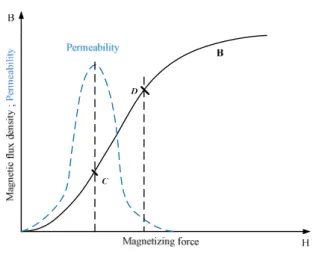
where B is the flux density, H is the magnetization force. In (2) the magnetic permeability is the only variable factor for any given core material. The flux density and magnetic permeability as a function of the magnetizing force is shown in Fig. 4.
Fig. 4. Flux density and magnetic permeability.
The values of the permeability increases to a maximum, achieved where the B curve reaches the knee (inflexion point). After this point the permeability value decreases quickly, asymptotically going to zero, with H to increase. If the core permeability of the reactor will vary in the linear region of the curve, then the reactance of the coil reactor will vary linearly as well. The method used to obtain the linear change of permeability is to operate at the knee of the magnetization curve (B/H) curve. In this way, the magnetic permeability change is a linear function of the magnetization force H, even for larger AC component applied [8,9]. The larger space left for the AC component is important for this reactor, prepared for power applications.
The layout of the magnetic core reactor with the two circuits, i.e., the load circuit and the control circuit is shown in Fig. 5.
Fig. 5. Flux density and magnetic permeability.
In Fig. 5 the current that flows in the load circuit is the current IL. The IL is limited by Rload and the reactance LL of the coil NL.
The value of the inductance LL is given by (2). When the DC control current Ic is allowed to flow in this circuit, the permeability of the magnetic core will be changed, since Ic will cause the operating point C to shift to point D (Fig. 2). Them, this change in the permeability core material has caused the reactance of LL to decrease and consequently the coil reactance to decrease too, allowing more current to flow through the Rload. This is the process controlled by the varying of the DC control current Ic. It is possible to vary the load current IL and consequently to vary the voltage at the terminals of the load resistance.
In Fig. 5 the AC source voltage applied to the load circuit, is given by:
( )
t t v =Vmcosω (4) where: dt d t N Vmcosω
= cφ
(5)Here, in (5), Nc is the winding control turn number,
dt dφ is
the time rate of the change of the total flux linking the load circuit winding. Reformulating (5) is given by:
= tdt d N V c m ω φ cos (6)
Then the flux φ is given by:
φ ω ω φ= sin t+ 0 N V c m (7)
where Ø0 is the initial flux. The flux density B is given by:
B
B t
S
B=
φ
= msinω
+ 0 (8)where S is the core surface, B0 is the initial flux density. Comparing (7) and (8) the maximum flux density is given by:
S S N V B c m m m
ω
φ = = (9)III. PROTOTYPE RESULTS
The transmitter inductance variation and MCR inductance variation in function of the DC control current are shown in Fig. 6.
Fig. 6. MCR and transmitter inductances in function of the DC current.
The diagram of the circuit to obtain the inductance value of the MCR in function of the DC control current was implemented in the prototype as shown in Fig. 7.
Fig. 7. Circuit to collect the inductance values function of the DC current.
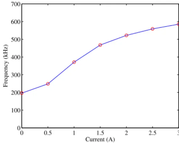
The circuit to obtain the inductance value of the MCR plus the transmitter coil was implemented in the prototype as shown in Fig. 8. The range of the working frequencies of the prototype in function of the DC control current is shown in Fig. 9.
The inductance values were observed during a varying of the DC current (measured by the ampere meter, connected in
series in the control circuit). The inductance values are measured by the Digital LCR test equipment. The same procedures were taken to collect the inductance values of the MCR connected in series with the transmitter coil as shown in Fig. 8.
Fig. 8. Circuit to collect the inductance value of the MCR plus transmitter coil.
Fig. 9. Prototype working frequencies range.
The tuning capacity of the resonant transmitter circuit, i.e., the total Lt and Ct values to the transmitter resonant circuit [16] is shown in Fig. 10.
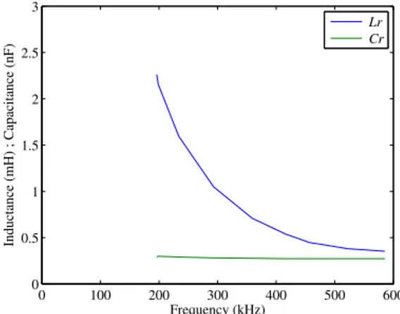
The tuning capacity of the resonant receiver circuit, i.e., the total Lr and Cr values to the receiver resonant circuit is shown in Fig. 11.
The capacitance is constant and when the MCR inductance changes, the total inductance of the circuit changes too, once the transmitter coil is connected in series with the MCR. When, the total inductance varies, consequently the resonant frequency also varies.
The prototype partial view is shown in Fig. 12. The transmitter and the receiver (2 MCRs) are shown in the bottom
0 0.5 1 1.5 2 2.5 3 0 0.5 1 1.5 2 2.5 3 Current (A) Inductance (mH) Lt Lmcr 0 0.5 1 1.5 2 2.5 3 0 100 200 300 400 500 600 700 Current (A) Frequency (kHz)
of the Fig. 12. The red coil is the transmitter coil and the white coil is the receiver coil. The driver coils are embedded in each transmitter and receiver sets of coils.
Fig. 10. Tuning capacity of the resonant transmitter circuit.
Fig. 11. Tuning capacity of the resonant receiver circuit.
Fig. 12. Prototype partial view of the transmitter and receiver MCRs.
The overall image from the prototype constituted by transmitter and receiver coils and the driver coils is shown in Fig. 13. The transmitter driver coil receives the power from the signal generator.
The input power pulses may have the same frequency (or higher than) the resonant frequency of the circuit formed by the transmitter coil, magnetic core reactor and the transmitter
resonant capacitor. The receiver circuit formed by receiver coil, the magnetic core reactor and the receiver resonant capacitor should be tuned to the first harmonic of the primary switching frequency. This condition is essential to obtain the maximum power transmission efficiency.
The defined best tuning points of the transmitter and the receiver circuits can be adjusted through the introduced magnetic core reactors.
Fig. 13. Overall image from the prototype.
IV. CONCLUSION
The energy transfer in the mid-range WPT is made by the magnetic flux. To obtain the maximum transfer of energy it is fundamental that the tuned frequency operation point of the transmitter and the receiver will be the same. Once this condition is fulfilled since the beginning, the control system will have continuous capability to readjust the frequency. In this project the control system is based on the magnetic core reactor. The tests already made have shown the functionality of the magnetic core reactor principle when applied to this control system.
This process enables the operation frequency adjustments in a WPT system. With this frequency adjustment process, it is possible to match the impedances between the transmitter and the receiver circuits and to increase the efficiency of the contactless power transmission system.
The control method proposed here by applying of magnetic core reactor allows a significant improve compared to other control methods, usually applied.
REFERENCES
[1] X. Lu, P. Wang, D. Niyato, D.I. Kim, and Z.J. Han, “Wireless charger networking for mobile devices: fundamentals, standards, and applications,” IEEE Wireless Communications, vol. 22, pp. 126-135, April 2015.
[2] X.L. Huang, W. Wang, L.L. Tan, L.L. Zhao, and Y.L. Zhou, “Study of transmission performance on strong coupling wireless power transfer system in free position,” Proc. of the Progress in Electromagnetics Research Symposium, p. 669-676, 2012.
[3] A. Barili, A. Brambilla, G. Cottafava, and E. Dallago, “A simulation model for the saturable reactor,” IEEE Transactions on Industrial Electronics, vol. 35(2), pp. 301-306, 1988. 0 100 200 300 400 500 600 0 0.5 1 1.5 2 2.5 3 Frequency (kHz) Inductance (mH) ; Capacitance (nF) Lt Ct 0 100 200 300 400 500 600 0 0.5 1 1.5 2 2.5 3 Frequency (kHz) Inductance (mH) ; Capacitance (nF) Lr Cr Transmitter MCR Receiver MCR
[4] L. Austrin, and G. Engdahl, “Modelling of a three-phase application of a magnetic amplifier,” Proc. of the 24th International Congress of the Aeronautical Sciences, p. 1-8, 2004.
[5] L. Romba, S. Valtchev, and R. Melicio, “Three-phase magnetic field tested in wireless power transfer system,” International Review of Electrical Engineering, vol. 11(6), pp. 586-597, November-December 2016.
[6] S.G. Cimen, A. Pfannkuchen, and B. Schmuelling, “Compensation considerations for bidirectional inductive charging systems of electric vehicles with coil positioning flexibility,” IEEE Transactions on Magnetics, vol. 52(3), pp. 1-4, March 2016.
[7] J.A. Russer, M. Dionogi, M. Mongiardo, and P. Russer, “A bidirectional wireless power transfer system for roadway powered electric vehicles,” Microwave Review, vol. 19(2), pp. 68-75, 2013.
[8] L.F. Romba, S. Valtchev, and R. Melício, “Three-phase magnetic field system for wireless energy transfer,” Proc. of the International Symposium on Power Electronics, Electrical Drives and Motion, p. 73-78, 2016.
[9] J.-L.W. Hsu, A.P. Hu, and A. Swain, “A wireless power pickup based on bidirectional tuning control of magnetic amplifier,” IEEE Transactions on Industrial Electronics, vol. 56(7), pp. 2771-2781, July 2009.
[10] L.F. Romba, S. Valtchev, and R. Melício, “Improving magnetic coupling for battery charging through 3d magnetic flux,” Proc. of the IEEE International Power Electronics and Motion Control Conference, p. 291-297, 2016.
[11] L.F. Romba, S. Valtchev, and R. Melício, “Wireless energy transfer with three-phase magnetic field system: experimental results,” Proc. of the International Conference on Renewable Energies and Power Quality, p. 1-5, 2016.
[12] Jr J.A.F. Barbosa, J.C. Oliveira, T.V. Silva, I.N. Gondim, F.P. Santilio, and L.N. Velasco, “Modelling and validation of the magnetizing curve to represent saturated core reactor using atp simulator,” Proc. of the International Conference on Renewable Energies and Power Quality, p. 1-6, 2016.
[13] A. Dimitrovski, Z. Li, and B. Ozpineci, “Magnetic amplifier-based power-flow controller,” IEEE Transactions on Power Delivery, vol. 30(4), pp. 1708-1714, August 2015.
[14] L.F. Romba, S. Valtchev, R. Melício, “Single-phase wireless power transfer system controlled by magnetic core reactors at transmitter and receiver,” in Technological Innovation for Smart Systems, vol. 499, L.M. Camarinha-Matos et al., Eds. Springer, DOI: 10.1007/978-3-319-56077-9_41, 2017.
[15] X. Lu, P. Wang, D. Niyato, D.I. Kim, and Z. Han, “Wireless charging technologies: fundamentals, standards, and network applications,” IEEE Communications Surveys and Tutorials, vol. 18(2), pp. 1413-1452, November 2015.
[16] L.F. Romba, E.N. Baikova, S. Valtchev, R. Melício, “Electric vehicle battery charger: wireless power transfer system controlled by magnetic core reactor,” Proc. of the Conference on Electronics, Telecommunications and Computers, p. 1-2, 2016.