Abstract—In this paper, an optical coupler composed by a photonic quasi-crystal fiber (PQCF) with two cores is proposed. The structure is obtained by immersion of a quasi-periodic arrangement of air holes replicated twelve-fold in a conventional fiber optical constituted of pure silica. The cores are generated from defects caused due to absence of two air holes on each identical core and horizontally equidistant from the center of PQCF. The chromatic dispersion in each fiber core is ultra-flat around 38.12 ps.nm-1.km-1 and to verify the power transfer, the signal was launched on the left core and transferred to the right core in a propagation length of approximately 3.78 cm.
Index Terms—Photonic Quasi-Crystal Fiber; Optical Coupler; Extended Cores.
I. INTRODUCTION
The basic geometry of a photonic crystal fiber (PQCF) is formed by an arrange of
quasi-periodic air holes whose depth extends along the length of the fiber. These types of optical fibers,
represent a class of structures that exhibit an important feature of do not have translational symmetry,
normally found in the traditional photonic crystals (CFs), which are structured materials, where their
geometrical functions varies periodically in space [1]. The photonic quasi-crystals (PQC) are
characterized by an unusual alignment of atoms forming ordered aperiodic structures, having at least
two different symmetrical patterns, which also form a gap-free structure, but they are not repeated
regularly [2]. Geometrical reasons reduce the possibilities of symmetries, and after an analysis one
can conclude that only 6, 8, 12 and 24-fold symmetries are possible.
As in photonic crystal fibers (PCF), a PQCF can be defined by the geometric parameters Λ (pitch), the
center-to-center distance between the air holes, and the air hole diameter d. In addition, a PQCF is
also characterized by the number of times that the matrix formed by the quasi-periodic arrangement,
that is basic matrix, is repeated in the core of pure silica. The PQCF proposed in this work is shown in
Figure 1 (a). and the basic matrix is shown in Figure 1 (b). In addition, the introduction of symmetries
with an aperiodic array of air holes, in a dielectric matrix with low refractive index produces photonic
band gaps, i.e., disallowed bands of frequency in which the light propagation is totally banned [3]. In
the limit, for small wavelengths (Λ/λ→ ∞), the light is forced to remain only in the region of defects
due to the total internal reflection phenomenon. The PQCF presents manufacturing configurations that
are similar to the processes used in manufacturing the PCF, that is, they are commonly fabricated
using pure silica, doped silica or polymeric materials, and the microstructure of the shell is obtained
Directional Coupler Based on a Photonic
Quasi-Crystal Fiber with Extended Cores
J. P. da Silva1, Einstein G. dos Santos2 and Marcos T. B. Segundo3 1,2,3
Brazilian Microwave and Optoelectronics Society-SBMO received 26 Oct 2017; for review 26 Oct 2017; accepted 05 Apr 2018 with the inclusion of materials with lower refractive index, commonly with holes filled with air or
some other material with refractive index lower than the base material [1], [4].
In addition, an important feature of the structures based on photonic quasi-crystals, lies in the fact
that the use of repetitions of the basic cell to mount the structure, can present a high degree of
symmetry. Considering the significant band-gaps achieved with these models of structures in the
optical range, it has the possibility to fabricate photonic devices that enable a reduction in the
coupling losses that are associated with the transition of light in the waveguide interface. This
characteristic represents an advantage of the use of PQCF in relation to the PCF [5].
In the next section, the finite element formulation including perfect matched layers (PML) of
cylindrical type are briefly presented, concepts for PQCF project are described in section III,
numerical results are shown in section IV, and finally the conclusions of this work are presented.
II. METHOD OF ANALYSIS
The finite element method (FEM) is a mathematical tool widely used in telecommunications,
specifically in the numerical analysis of propagation characteristics in optical fibers [6]. One can
define the FEM as a numerical technique for finding approximate solutions to boundary value
problems for partial differential equations (PDE). In this work, the FEM is applied to obtain the neff
effective refractive index from which it is possible to find the chromatic dispersion D, which acts
directly on the transmission quality of the waveguide [7]. In addition, the Sellmeier coefficients were
used in the vector formulation to examine the chromatic dispersion, the variation of the effective
index and the effective area of the fundamental mode at different frequencies.
The Sellmeier coefficients can be applied, without loss of generality, directly to the vector
formulation. In essence, these coefficients can be calculated from the Helmholtz differential equation, obtained from Maxwell’s equations in differential form:
0 2
0
k H k H (1)
wherek1/(L), in which represents the permittivity tensor or dielectric tensor, and L
corresponds to a tensor that relates the parameters of the cylindrical PML [8]. After some algebraic
manipulation and assuming that in both medias the fields vary relatively slowly along the propagation
direction z [6], the equation (1) can be rewritten as:
A
neff2
B
(2)where [A] e [B] are sparse and complex matrices. Equation (2) is efficiently solved by subspaces
method. Here, the FEM is applied together with the vectorial beam propagation method (VBPM) [6]
III. PQCF DESIGN
The proposed structure is composed of pure silica and is characterized by a quasi-periodic array
with microscopic air holes forming an arrangement with 12-fold symmetry, Figure 1 (a). The air holes
are separated by and have equal diameters d, except for the central hole, which has a varying
diameter dc. The structure consists of two identical cores horizontally equidistant from the central air
hole. The cores are distributed in order to permit maximum energy transfer between them. Figure 1
(b) shows the used quasi-periodic array to design the geometry with repetition of 12-fold symmetry
and the hexagonal structure containing the adjusted diameter of the central air hole is shown in Figure 1 (c). It is important emphasize that the is usually constant and presents a significant effect on the
chromatic dispersion curve localization [8].
Fig. 1 (a) Cross section of a PQCF with 12-fold symmetry and extended and identical cores 1 e 2, (b) Basic matrix of the
quasi-periodic array and (c) Central air hole detail.
In the design of this new fiber, the extended cores are obtained by introducing a defect caused by
removing two neighboring air holes, located near the central air hole of the quasi-crystalline mesh,
which forms the pattern structure of repetitions. In fact, removing the air holes does not affect the
symmetry of repetitions along the length of the fiber, since these defects are located at equidistant and
symmetrical points in relation to the horizontal line center of the PQCF transversal section. Another
point remains in the fact that the photonic quasi-crystals can have their symmetry and geometry
predefined, which allowed the development of this design [9]. It is important to emphasize that the
crystalline structure was obtained by intercalating air holes, which were immersed in pure silica with
a corresponding wavelength of 1.55 µm.
IV. RESULTS
In this work, a study was first performed considering the structure composed by just core 1 and then
the core 2. In both cases, the PQCF is formed with 12-fold symmetry and values of d = 1.2 m, d/ =
0.5 e = 1.55 µm. Here, the objective was to verify the effective area of the structure and the
Brazilian Microwave and Optoelectronics Society-SBMO received 26 Oct 2017; for review 26 Oct 2017; accepted 05 Apr 2018 The effective modal area refers to the area of the fiber where optical power is effectively
transmitted. To obtain this area in the analyzed PQCF, the energy beam was launched into the left
core (core 1), assuming the right core without defects, next the signal was launch into the core 2,
considering the left core without defects, the same procedure was adopted to obtain the chromatic
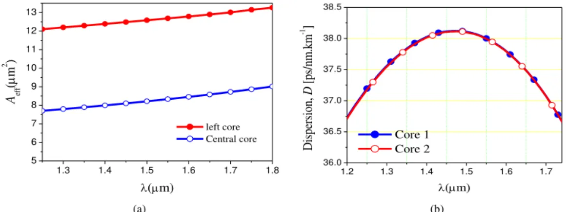
dispersion in the cores 1 and 2. Figure 2 (a) shows a comparison between the effective modal area of
the left extend core (where the core is obtained due defect caused by removing two air hole) and
central core. To obtain the effective area in the central core, the defect was introduced due removing
one air hole only in the hexagon of the structure center. In addition to the effective modal area, all
simulation were obtained using the expression A
E dxdy
E dxdy
eff
4 2
2 [7], where E is the
transverse electric field and the material which constitutes the PQCF is pure silica with refractive
index of 1.44. To obtain the Aeff and the chromatic dispersion, it was consider dc = d and the
computational window for all simulations was divided into 18,368 linear elements. The effective area
for the PQCF in analysis is proportional to the diameter of the modal field. Thus, the PQCF with
extended cores have a larger effective area when compared to the single core PQCF in the center of
the structure. This way, we can conclude that the PQCF with extended core can transmit a greater
amount of power.
To obtain the chromatic dispersion as a function of the wavelength was used the expression D = - (/c) (d2neff / d
2
), where c represents the speed of light in free space. The chromatic dispersion
obtained is ultra-flat and varies between 36.75 e 38.125 ps/(km.nm) for a range of wavelengths from
1.2 m to 1.74 m as shown in Fig. 2 (b).
(a) (b)
Fig. 2 (a) Effective Area (Aeff) of the left and central cores in function of wavelengths from =1.25m to =1.8m and (b)
Chromatic dispersion for the structure showed in Fig. 1, considering the analysis for the cores 1 e 2 separately with dc = d =
1.2 m.
In the Figure 2 (b) we can see that the structure presents a flat and positive dispersion to a range of
wavelengths for layers E+S+C+G+U approximately 37.5 ps.km-1.nm-1 for the cores 1 and 2
individually. A possible application to the coupling structures analyzed in this paper, could be its use
for the power transmission with chromatic dispersion adjustment for the wavelength range considered
1.3 1.4 1.5 1.6 1.7 1.8
5 6 7 8 9 10 11 12 13 left core Central core Aef f ( m 2 )
(m)
1.2 1.3 1.4 1.5 1.6 1.7
36.0 36.5 37.0 37.5 38.0 38.5 Core 1 Core 2 D is pe rs io n, D [p s/ nm .k m -1 ]
and results obtained in this analysis.
For the second application, we considered the structure shown in Figure 1 (a) with two cores to
perform the analysis of the coupling characteristics at the wavelength = 1.55 m. The energy
transfer can be controlled by varying the diameter of the air hole dc introduced into the hexagon
located in the center of PQCF. Here, the fiber was excited with the signal launched into the core 1
corresponding to the mode E11x, for which the effective refractive index (neff) obtained through modal
analysis [10].
The coupling distance obtained from VBPM is in accordance with the distance obtained using the
modal analysis through the relation LB/(eff1eff2) where LB is the beat length, and eff1 and eff2
correspond to the propagation constant of the super-symmetric and anti-symmetric mode of the lowest
order. Figure 3 shows the power transfer between the cores 1 and 2 of PQCF along the direction of
propagation. The red curve with empty squares corresponds to the power variation in the core 1 and
the red curve with filled squares represents the power variation in the core 2, considering dc = 0.684
µm. The blue curve with empty circles corresponds to the power variation in the core 1, the blue curve
with filled circles represents the power variation in the core 2, considering dc = 0.3 µm. The black
curve with empty triangles corresponds to the power variation in the core 1 and the black curve with
filled triangles corresponds to the power variation in the core 2, considering dc = 0 µm.
Fig. 3. Distance of maximum power transfer for the PQCF with two cores considering dC = 0.684 µm, dC = 0.3 µm e dC = 0
µm para 1 = 1.55 e d/=0.5.
From the results, it is observed that, for the first diameter dc = 0.648 μm, the energy launched into
the core 1 is totally transferred to the core 2 in the propagation distance of Lc = 23.46 cm. For dc =
0.300 μm, the energy launched in core 1 is totally transferred to the core 2 in the propagation distance of Lc = 7.6 cm and when we consider the central hexagon of PQCF with dc = 0 μm, the energy
launched into the core 1 is totally transferred to the core 2 in a propagation distance Lc = 3.78 cm.
It is important to note that the absence of defect in the central air hole, where d = 0 μm, does not
0 1 2 3 4 5
0,0 0,2 0,4 0,6 0,8 1,0
d
c
= 0.0
m
d
c= 0.3
m
d
c
= 0.684
m
Normaliz
ed Po
wer
Brazilian Microwave and Optoelectronics Society-SBMO received 26 Oct 2017; for review 26 Oct 2017; accepted 05 Apr 2018 characterize the inclusion of a third core in fiber, because no energy is stored in the central hexagon
during the transfer of energy between the cores 1 and 2. However, when a defect in the core of the
central hexagon is caused, there is a high sensitivity in the power transfer between the cores, that is,
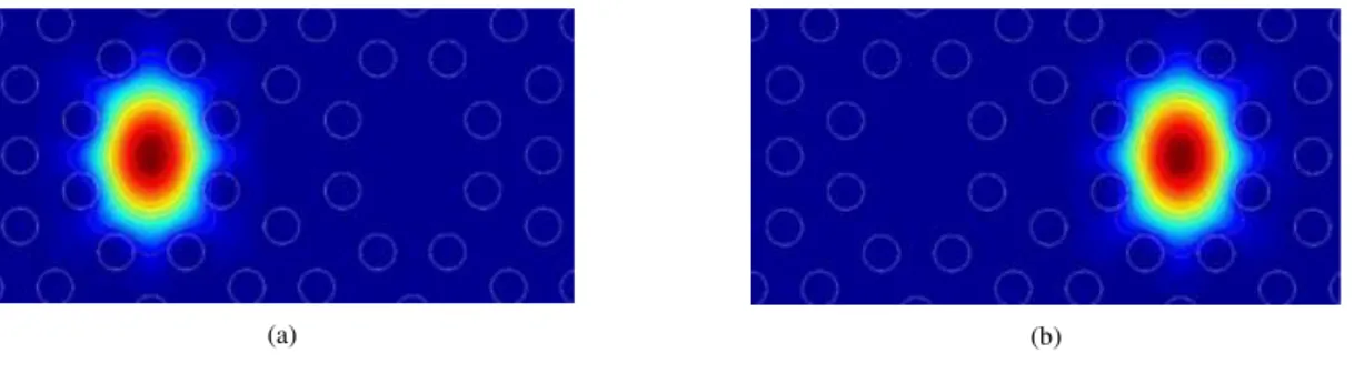
small variations in the diameter dc provoke large variations in the coupling distance. Finally, Figure 4
shows the electric field distribution from the simulation with VBPM for propagation distance z = 0
and Lc for = 1.55 μm.
(a) (b)
Fig. 4. Electric field distribution in (a) z = 0 e (b) z = Lc.
In addition, as an application using structures based in photonics quasi-crystals, recently, optical beam
couplers were developed from networks photonics quasi-crystals with twelve-folds symmetry. In this
case, the device was constructed by random stampfli inflation, etched in silicon oxynitride slab
waveguide deposited on silicon dioxide [11]. On the other hand, making a parallel between the
structure analyzed in this paper and the couplers based on PQCF, we can consider the advantage of
PQCF to facilitate the use of the extended cores due to the arrangement of air holes and its
twelve-fold symmetry, which does not occur in PCF due to the periodicity of the air holes hexagonal rings
distribution.
V. CONCLUSIONS
In this work, a new design of an optical coupler formed by a PQCF with two extended cores was
proposed. The values of the structural parameters were obtained with the aim of improving the
performance of the PQCF optical coupler. The modal analysis of PQCF, considering the cores
isolated, was performed in order to obtain a chromatic dispersion in each of the cores of the fiber as
being ultra-flat around of 38.12 ps.nm-1.km-1. In the C-band, that corresponds to the optical
wavelength range from 1530 nm to 1565 nm, the slope of the dispersion curve was around 0.0015
ps.nm-1.km-2. The results obtained show that all the energy launched into the core 1 was transferred to
the core 2 of the PQCF in a propagation distance of 3.78 cm for dc = 0 µm. The sensitivity analysis of
this fiber relative to the diameter of the central air hole was shown in Figure 3. The variation of these
parameters was introduced under the assumptions that the others remain constant. For this analysis, it
is clear that for an increase of 5.0% dc results in an increase of approximately 10% in the coupling
ACKNOWLEDGMENT
The authors would like to thank the structural support of the UFRN and UFERSA and financial
supports of the CAPES and CNPq.
REFERENCES
[1] S. Kim, C. S. Kee and J. Lee, “Novel Optical Properties of Six-Fold Symmetric Photonic Quasicrystal Fibers”, Opt. Express, v. 15, pp. 13221-13226, 2007.
[2] S. Kim and C. S. Kee, “Dispersion Properties of Dual-Core Photonic Quasicrystal Fibers”, Optics Express, V. 15, 15885-15890, 2009.
[3] L. Yu-He, F. Wan-De and S. Qiu-Qin, “A novel Photonic Quasicrystal Fiber with Broadband Large Negative
Dispersion”, Chine Physics Letters, V. 27, 114211-1-4, 2010.
[4] M.J. Gander, R. McBride, J.D.C. Jones, D. Mogilevtsev, T.A. Birks, J.C. Knight, and P.St.J. Russell, “Experimental
measurement of group velocity dispersion in photonic crystal fibre,” Electronic Letters, V. 35, 63–64, 1999.
[5] Robert C. Gauthier and Alexei Ivanov, “Production of quasi-crystal template patterns using a dual beam multiple exposure technique”, Optical Express, V. 12, 990-1003, 2004.
[6] J. P. da Silva, H. E. Hernández-Figueroa and A. M. F. Frasson, “Vectorial finite-element BPM analysis for transverse anisotropic media”, J. Lightwave Technology, V. 21, 567-576, 2003.
[7] K. Saitoh, N. Florous, and M. Koshiba, "Ultra-flattened chromatic dispersion controllability using a defected-core photonic crystal fiber with low confinement losses," Optics Express V. 13, 8365-8371 (2005).
[8] Xin Cheng, Ming-Jun Li, J. Koh, A. Artuso and D. A. Nolan, “Effects of bending on the performance of hole-assisted single polarization fibers” Optics Express, V. 15, 10619-10636, 2007.
[9] Weicheng Cai. Exian Liu, Bo Feng, H. Liu, Z. Wang, W. Xial T. Liang, S. Wang, J. Liu and Jianjun Liu, “ Dispersion
proparties of a photonic quasi-crystal fiber with double cladding air holes”, Elsevier Optik, V. 127, 4438-4442, 2016.
[10] J. P. da Silva and E. R. M. Dantas, “ Modal anlysis of a photonic quasi-crystal fiber of silica doped with germanium”, International Microwave & Optoelectonics Conference (IMOC), 2013 SBMO/IEEE MTT-S, 1-5, 2013.
[11] Jingxing Shi, Michael E. Pollard, Cesar A. Angeles, Ruiqi Chen, J. C. Gates and M. D. B. Charlton, “Photonic crystal and quasi-crystals providing simultaneous light coupling and beam splitting within a low refractive -index