Faculdade de Engenharia da Universidade do Porto
Emerging Technologies and Future Trends in
Substation Automation Systems for the
Protection, Monitoring and Control of
Electrical Substations
Bruno Tiago Pires Morais
F
INALV
ERSIONMaster in Electrical and Computer Engineering
Major Automation
Advisor: Hélder Leite (Professor)
Supervisor: Mário Lemos (Engineer)
!
Resumo
O conceito de subestação inteligente é baseado em tecnologias “state-of-the art” para automação de subestações, e visa permitir uma mais fiável e eficiente proteção, monitorização, controlo, operação e manutenção dos equipamentos e aparelhos instalados nas subestações, bem como responder rapidamente a falhas no sistema e oferecer maior segurança aos operadores. Os Sistemas de Automação de Subestações são responsáveis pela proteção, monitorização e controlo de todo o processo eléctrico de uma subestação eléctrica, e tanto a arquitetura do sistema como a sua estrutura organizacional tornam o sistema fiável, flexível, modular e fácil de expandir. A evolução dos Sistemas de Automação em Subestações teve início na substituição dos relés electromagnéticos por relés numéricos, e prosseguiu com a implementação de comunicações digitais ao nível da subestação, mas ainda sujeitas a protocolos proprietários. Em seguida, o IEC 61850 foi introduzido, e a interoperabilidade entre diferentes dispositivos tornou-se possível, mas o próximo grande passo na evolução da automação de subestações surgirá com a implementação do barramento de processo. O barramento de processo interliga os dispositivos de proteção e controlo ao nível de painel, com os transformadores de medida e equipamento de corte ao nível de processo. Com isso, os fios de cobre convencionais serão substituídos por cabos de fibra óptica, e a transmissão de medidas de corrente e tensão, assim como de sinais de proteção e comando terá lugar sobre uma rede de ligações série, em vez de ligações paralelas ponto a ponto. O barramento de processo torna possível a substituição de transformadores de medida electromagnéticos convencionais por modernos sensores ópticos de corrente/tensão, e a implementação de sistemas de monitorização da condição de ativos. A manutenção preditiva é extremamente importante nos esforços dos operadores para lidar com a redução de pessoal e as exigências crescentes dos clientes para melhor qualidade da energia e fiabilidade no fornecimento de energia. Além disso, os transformadores de potência são os ativos mais caros numa subestação e, portanto, a sua monitorização é essencial para garantir uma manutenção eficiente e a utilização óptima das suas capacidades operacionais. Assim, dispositivos de monitorização on-line para diagnóstico de transformadores, usando a Análise de Gases Dissolvidos para medir o nível de gases combustíveis e humidade no óleo de isolamento, estão a tornar-se cada vez mais populares para avaliar o estado de saúde de um transformador em tempo real.
Abstract
The smart substation concept is built on state of the art automation technologies for substations, and should enable a more reliable and efficient protection, monitoring, control, operation, and maintenance of the equipment and apparatus installed within the substations, as well as rapidly respond to system faults and provide increased operator safety. Substation automation systems are responsible for the protection, monitoring and control of all electric process within an electric substation, and both the system architecture and its organizational structure make the system reliable, flexible, modular and simple to expand. Substation automation systems evolution went from electromagnetic to numerical relays at first, and followed with the implementation of digital communications at station level, but still subjected to proprietary protocols. Then the IEC 61850 was introduced, and interoperability between different devices became possible, but the next big step in the evolution of substation automation will come with the implementation of the process bus. The process bus interconnects the protection and control devices at bay level, with the instrument transformers and switchgear equipment at process level. With it, conventional copper wires will be replaced by fibre optic cables, and the transmission of current and voltage samples, as well as protection and command signals will be over a serial link network, instead of parallel point-to-point connections. The process bus makes it possible to replace conventional electromagnetic instrument transformers by novel optical current/voltage sensors, and to implement assets condition-monitoring systems. Predictive maintenance is extremely important in the efforts of utilities to deal with reduced personnel and increasing customer requirements for improved power quality and reliable power supply. In addition, Power Transformers are the most expensive asset in a substation, and so monitoring is essential to provide efficient maintenance and optimal use of their operational capacities. Therefore, on-line monitoring devices for transformer diagnostics, using the Dissolved Gas Analysis to measure the level of combustible gases and moisture in the insulating oil, are becoming increasingly popular to evaluate a transformers health condition in real-time.
Acknowledgements
I would like to thank first and foremost to my parents to whom I owe everything. I am very thankful for their unconditional help and support in every decision I made. They helped shape me into the person I am today. And none of what I achieved in life would have been possible without them, and for that I am forever grateful. I am also very grateful to my advisor, Professor Helder Leite, and to my supervisors, Engineers Mario Lemos and Carlos Peças Lopes, for their guidance and for sharing their knowledge and expertise with me. I am very pleasant for the opportunity, which was given to me, of doing my thesis project at EDP Energias de Portugal, to which I am also thankful. My special thanks to, and in no given order, Antonio Azevedo, Antonio Silva, Duarte Duarte, Fernando Moreira, José Ramos, Pedro Carvalho, and Diogo Oliveira, who passed away, for being with me every single day since I got in at the Faculdade de Engenharia da Universidade do Porto, and for making this journey an easy and pleasant one.
Finally, it would be inappropriate to specify names, since they are so many that I could fail to mention some, but I would like to thank all my friends, friends from my hometown, friends from university, friends I become with when as an exchange student at the Royal Institute of technology in Stockholm, friends from Portugal Telecom which was the first company I worked for, friends I become with while in London when working for the European Bank for Reconstruction and Development, friends from EDP Energias de Portugal the company where I am doing my thesis project right now, and from all the groups and societies I am member of, for I am much appreciated. I am very grateful indeed, for their support along all this years, for making my day every single day ever since, and for pushing me to take this endeavour of stop working and doing my thesis after almost 5 years out of university.
Thank You All, Bruno
“A journey of a thousand miles begins with a single step.”
Contents
Resumo ... iii
!
Abstract ... v
!
Acknowledgements ... vii
!
Contents ... xi
!
List of Figures ... xv
!
List of Tables ... xvii
!
Acronyms & Symbols ... xix
!
Chapter 1 ... 1
!
Introduction ... 1!
Thesis Proposal ... 2!
1.1!
– Problem Definition ... 3!
1.2!
– Research Approach ... 3!
1.3!
– Expected Results ... 4!
Chapter 2 ... 5
!
Smart Substations (Literature Review) ... 5
!
2.1
!
– The Smart Grid ... 6!
2.1.1 – Required Functional Areas ... 6
!
2.1.2 – Characteristics and Requirements ... 6
!
2.2
!
– The Smart Substation ... 8!
2.2.1 – Technical Characteristics ... 9
!
2.2.2 – Functional Requirements ... 9
!
2.3
!
– Intelligent Electronic Devices ... 12!
2.3.1 – Electromechanical Relays ... 12
!
2.3.2 – Solid-State Relays ... 13!
2.3.3 – Computer Relays ... 14!
2.4!
– Communication Networks ... 14!
2.4.1 – Communication Media ... 15!
2.4.2 – Network Topology ... 15!
2.4.3 – Communication Protocols ... 17!
2.5
!
– The IEC 61850 Standard ... 20!
2.5.1 – Legacy Protocols ... 20
!
2.5.2 – IEC61850 Standard ... 21
!
2.5.4 – Future Trends ... 26
!
2.6
!
– Summary ... 27!
Chapter 3 ... 29
!
Substation Automation Systems ... 29
!
3.1
!
– Standard Substation ... 30!
3.1.1 – Station Switchyard ... 30!
3.1.2 – Auxiliary Equipment ... 31!
3.1.3 – Operating Room ... 31!
3.1.4 – Panels Line-up ... 31!
3.2!
– Introduction ... 32!
3.2.1 – General Characteristics ... 32!
3.2.2 – Relays & Control Panels Definition ... 33
!
3.2.3 – Relays & Control Devices Layout ... 34
!
3.2.4 – Equipment Layout ... 35
!
3.2.5 – Bay Diagrams ... 36
!
3.3
!
– Protection, Monitoring and Control ... 39!
3.3.1 – Physical System Architecture ... 39
!
3.3.2 – Logical System Architecture ... 40
!
3.4
!
– System Functionalities ... 42!
3.4.1 – Protection Functions ... 42
!
3.4.2 – Control Functions ... 44
!
3.4.3 – Other Functions ... 45
!
3.5
!
– Applications & Services ... 45!
3.5.1 – Primary Applications ... 45
!
3.5.2 – Support Services ... 46
!
3.6
!
– Summary ... 48!
Chapter 4 ... 51
!
Process Bus Implementation ... 51
!
4.1
!
– Introduction ... 52!
4.2
!
– The Process Bus ... 52!
4.2.1 – Historical Background ... 52
!
4.2.2 – Main Benefits ... 53
!
4.2.3 – Technical Issues ... 54
!
4.2.4 – Future Architecture ... 54
!
4.3
!
– Sensors and Actuators ... 55!
4.3.1 – Novel Instrument Transformers ... 55
!
4.3.2 – Disconnecting Circuit Breakers ... 57
!
4.4
!
– Switchgear Digital Interfaces ... 58!
4.4.1 – Merging Unit ... 58
!
4.4.2 – Breaker IED ... 59
!
4.5
!
– Local Area Network Topology ... 60!
4.5.1 – Process Close Implementation Overview ... 60
!
4.5.2 – Process Close Architecture Details ... 62
!
4.5.3 – Reliability and Redundancy ... 63
!
4.5.4 – Verification, Validation and Testing ... 64
!
4.6
!
– Summary ... 65!
Chapter 5 ... 67
!
Assets Condition Monitoring ... 67
!
5.1
!
– Transformer Protection & Maintenance ... 68!
5.1.1 – Predictive Maintenance ... 68
!
5.1.2 – Benefits of Monitoring Devices ... 68
!
5.1.3 – Transformer Asset Management ... 68
!
5.2
!
– Transformer Monitoring & Diagnostics ... 69!
5.2.1 – Transformer Gas Analyser ... 70
!
5.3
!
– Dissolved Gas Analysis ... 72!
5.3.1 – Types of Faults ... 72!
5.3.2 – Gas Levels ... 73!
5.3.3 – Key Gases ... 73!
5.3.4 – Gas Ratios ... 74!
5.3.5 – Duval’s Triangle ... 75!
5.4
!
– Economic Appraisal of Monitoring ... 76!
5.4.1 – Cost–Benefit Analysis ... 76
!
5.4.2 – Probability of Failure ... 77
!
5.4.3 – Failure Costs Evaluation ... 78
!
5.4.4 – Deferring Replacement ... 79
!
5.4.5 – Overloading Benefits ... 80
!
5.5
!
– Summary ... 82!
Chapter 6 ... 83
!
Conclusions ... 83
!
6.1
!
– Analysis & Discussion ... 83!
6.2
!
– Future Work ... 86!
References & Bibliography ... 87
!
List of Figures
Figure 1.1 - Substation Automation Systems architecture for the Next-Generation
Substations. ... 4
!
Figure 2.1 - The Smart Grid characteristics and requirements [09]. ... 7
!
Figure 2.2 - Principle of construction of an induction disk relay [35]. ... 13
!
Figure 2.3 - A possible circuit configuration for a solid-state instantaneous overcurrent relay [35]. ... 13
!
Figure 2.4 - Star Network Architecture [08]. ... 16
!
Figure 2.5 - Cascading (Bus) Network Architecture [08]. ... 17
!
Figure 2.6 - Ring Network Architecture [08]. ... 17
!
Figure 2.7 - Example of PRP and HSR networks coupled through Redboxes [34]. ... 19
!
Figure 2.8 - Interconnection of a PRP network with a HSR network [34]. ... 20
!
Figure 2.9 - Substation Automation Topology [04]. ... 23
!
Figure 2.10 - Data Structure based on Logical Nodes [04]. ... 24
!
Figure 2.11 - Data Model and Communication Services [04]. ... 24
!
Figure 3.1 - Station Switchyard Blueprint [44]. ... 30
!
Figure 3.2 - Operating Room Blueprint [37]. ... 31
!
Figure 3.3 - HV Line / Power Transformer & Voltage Regulators [44]. ... 36
!
Figure 3.4 - Switched Busbar Circuit-Breaker + HV Busbar Potential [44]. ... 36
!
Figure 3.5 - High Voltage Power Line [44]. ... 37
!
Figure 3.6 - Main Power Transformer & Voltage Regulators [44]. ... 37
!
Figure 3.7 - HV Line Termination Structures [44]. ... 38
!
Figure 3.8 - Medium Voltage Power Line [44]. ... 38
!
Figure 3.10 - Present Substation Automation System Architecture [12]. ... 39
!
Figure 4.1 - Substation wide area network with a merged station/process bus and a communication architecture, which is fully compliant with the IEC61850 standard [12]. ... 55
!
Figure 4.2 - Rogowski coil principle [42]. ... 56
!
Figure 4.3 - Capacitive divider principle [42]. ... 56
!
Figure 4.4 - Optical current sensor [43]. ... 57
!
Figure 4.5 - Optical voltage sensor [43]. ... 57
!
Figure 4.6 - Merging unit connected to 3 single-phase voltage and current transformers [12]. ... 59
!
Figure 4.7 - Present architecture using both a station bus and conventional wiring links [12]. ... 60
!
Figure 4.8 - Architecture with a station bus and links to non-conventional instrument transformers [12]. ... 61
!
Figure 4.9 - Full process bus architecture with both a station bus at bay level, and a process bus using both non-conventional instrument transformers and breaker IEDs [12]. ... 61
!
Figure 4.10 - Traditional approach with conventionally connected switchgear [12]. ... 62
!
Figure 4.11 - Introducing new sensor technology with non-conventional instrument transformers [12]. ... 62
!
Figure 4.12 - Process close connection details of both non-conventional instrument transformers and intelligent circuit breakers resulting in a full process bus solution [12]. ... 63
!
Figure 5.1 - Schematic Representation of a Transformer Gas Analyser Installation. ... 70
!
Figure 5.2 - Photo-Acoustic Infrared Spectroscopy [55]. ... 72
!
Figure 5.3 - Duval’s Triangle method used in Dissolved Gas Analysis [55]. ... 76
!
Figure 5.4 - Probability of Failure Indices without Transformer Monitoring [54]. ... 78
!
Figure 5.5 - Probability of Failure Indices with Transformer Monitoring [54]. ... 78
!
Figure 5.6 - Deferring Transformer replacement [54]. ... 79
!
Appendix A.1 - Equipment Layout [44]. ... 92
!
Appendix A.2 - Operating Room [44]. ... 93
!
List of Tables
Table 3.1 — Switchgear - HV Panel [38]. ... 35
!
Table 3.2 — Switchgear – MV Panel [38]. ... 36
!
Table 3.3 — Protection functions implemented in each of the bay unit devices [38]. ... 41
!
Table 3.4 — Automation functions implemented in each of the bay unit devices [38]. ... 42
!
Table 5.1 — Dissolved Key Gas Composition Limits (ppm). ... 73
!
Table 5.2 — Gases generated by transformer faults. ... 74
!
Table 5.3 — Basic Gas Ratios used in Dissolved Gas Analysis. ... 74
!
Acronyms & Symbols
List of acronyms
AMI Advanced Metering Infrastructure ANSI American National Standards Institute AVR Automatic Voltage Regulator
CCTV Closed-Circuit Television CCU Central Control Unit
CIT Conventional Instrument Transformers CMD Condition Monitoring and Diagnosis
CT Current Transformer
D Energy Discharges
DCB Disconnecting Circuit Breaker DG Distributed Generation DGA Dissolved Gas Analysis
DNO Distribution Network Operator DSO Distribution System Operator FAT Factory Acceptance Test
FOVT Fibre Optical Voltage Transformer
GC Gas Chromatography
GOOSE Generic Object Oriented Substation Events GPS Global Positioning System
GSSE Generic Substation State Events
HAN Home Area Network
HMI Human-Machine Interface
HSR High-availability Seamless Redundancy
HV High Voltage
HVAC Heating, Ventilation, and Air Conditioning ICCP Inter-Control Centre Communication Protocol IED Intelligent Electronic Devices
IP Internet Protocol IRR Internal Rate of Return
ISO International Organization for Standardization LAN Local Area Network
LN Logical Node
LOS Line-Of-Site
LV Low Voltage
MG Micro Grids
MMS Manufacturing Message Specification MOCT Magneto-Optic Current Transformer MTBF Mean Time Between Fails
MU Merging Unit
MV Medium Voltage
NCIT Non-Conventional Instrument Transformers NER Neutral Earth Resistor
NLOS Non-Line-Of-Site
NOC Network Operations Centre NPV Net Present Value (NPV)
MOCT Magneto-Optic Current Transformer OSI Open Systems Interconnection PAS Photo Acoustic Spectroscopy PD Partial Discharges
PLC Programmable Logic Controller PMU Phasor Measurement Unit PRP Parallel Redundancy Protocol RBE Return by Exception
RTU Remote Terminal Units
SAS Substation Automation Systems SAT Site Acceptance Test
SCADA Supervisory Control And Data Acquisition SCL Substation Configuration Language
SV Sampled Values
SVC Static Var Compensator
T Thermal Faults
TASE Tele-control Application Service Element TCP Transmission Control Protocol
TDCG Total Dissolved Combustible Gases
UFLS Underfrequency Load-shedding and Restoration UVLS Undervoltage Load-shedding and Restoration VAR Volt-Ampere Reactive
VT Voltage Transformer
WACC Weighted Average Cost of Capital WSN Wireless Sensor Networks
XML eXtensible Markup Language
List of symbols
α Transformer Shape Parameter
Chapter 1
Introduction
The first chapter, Introduction, guides the reader through all the main topics covered on this report, providing an overview of each of the remaining chapters of the report. It also includes the Thesis Proposal with the problem definition, research approach, and expected results. Chapter two, Smart Substations, is intended to present the reader with a broad range of concepts about substation automation systems. It reviews some well-established technologies presently available for electrical substations, and introduces some upcoming trends in the power and energy industry.
The third chapter, Substation Automation Systems, covers the Protection, Monitoring and Control systems presently implemented in the standard substations of the Portuguese distribution network operator.
In the fourth chapter, Process Bus Implementation, we shall see what the process bus is, and why its implementation is so critical for the evolution process of electrical substations and substation automation systems.
This chapter, Assets Condition Monitoring, provides an overview of techniques commonly available for transformer asset management. It starts by presenting the reader with the benefits of switching from Schedule Maintenance to Predictive Maintenance, and showing the role of Intelligent Electronic Devices in the Condition Monitoring and Protection of Power Transformers.
The last chapter, Conclusions, makes a summary of all the main topics covered along this report, and provides guidance on future work for those willing to pursue with this project.
Thesis Proposal
The work carried out comes as an extension of the research done by Hélder Leite, Mário Lemos and André Morais in “A Survey of Protection, Automation and Control Systems in the Portuguese Distribution Substations”, [02] and is intended to go further into the novel technologies and future trends of substation automation systems.
Background
Substations are a crucial element in the transmission and distribution of electrical energy, with a primary role of transfer and transform electrical energy by stepping-up or down the voltage. To do this, high voltage switching equipment and power transformers are used, in addition to instrument transformers, which supply the status of the primary system to the secondary equipment. Substation Automation Systems are then used to control, protect and monitor the substations.
Problem
Since the majority of the substations were built in Portugal, more than 30 years ago, there has been a tremendous development of both the primary equipment (switchgear, power transformers) and the secondary equipment (protection, control and metering). Over the years, advances in electronics, information and communication technology changed the way substations are operated. This provides an opportunity to re-design the way new substations are built and retrofit the ones currently in operation.
Motivation
The motivation behind this work is, to study the existing and fore-coming technologies for the automation of substations, provided that they will enable a more reliable and efficient monitoring, operation, control, protection, and maintenance of the equipment and apparatus installed, as well as provide an increased operator safety and ensure high quality of service. Moreover, the implementation of substation automation should help improve financial performance, customer service, and organisational effectiveness.
Previous work
Previous work has been carried out at the bay level, and as of now the connection between Substation Automation systems is moving away from a rigid parallel copper wiring to serial links architecture. However, at the process level, the connection of the Substation Automation systems with the switchgear and instrument transformers is still left to analogue standards, and contact circuits for switchgear operations. Thus the need and importance of carrying out this research work for the distribution network operator.
1.1 – Problem Definition
Description of the Goals
The work that I am doing consists on the following three main activities. Firstly, evaluate emerging technologies and future trends for the Automation of Substations and the Protection, Monitoring and Control of electric power systems. Secondly, analyse the impact of the IEC 61850 communications standard and the process bus implementation on the Digital Instrumentation and Control of Electrical Substations. Finally, review novel Assets Condition Monitoring solutions and Predictive Maintenance methodologies for the Protection and Diagnosis of power transformers.
The outcome of this work is expected to bring major improvements for distribution network operator across the following three main operational areas: financial performance, customer service, and organisation effectiveness. In fact, time and costs reduction in the substation design, construction, commissioning and maintenance; along with increased quality of service and reduced number of outages; and also guarantied safety, efficiency and increased reliability on the operation of the electric power system; are some of the key benefits intended to achieve with this study.
1.2 – Research Approach
Methods to be Used
The research intended to be carried out will focus primarily on the Substation Automation Systems, but across all of its areas of application namely: Protection, Monitoring, Control, Instrumentation, Command and Supervision. In order to cover a wide and varied range of sources, the research will target academic papers, technical journals, articles from magazines, documents from conferences, as well as reports published by the main suppliers, and leader utilities in the sector. The purpose is to get a broad and deep understanding of the subjects previously referred getting the insights from the academic world, the equipment manufacturers, and the electric companies.
Limitations
With the purpose of managing all the information initially gathered, the literature review will be organised within the following 8 categories: Smart Sensing and Measurement, Communications, Autonomous Control and Adaptive Protection, Data Management and Visualisation, Monitoring and Alarming, Diagnosis and Prognosis, Advanced Interfaces with Distributed Resources, Real-Time Modelling, and Cyber Security. Then, due to the wide range of areas covered, and the need to focus on just a few of them, on a later stage the analysis is going to be narrowed down to just the following 3 topics: Substation Automation Systems, Process Bus Implementation, and Assets Condition Monitoring.
1.3 – Expected Results
Results and Conclusions
The latest step in substation development comes with the introduction of the communications standard IEC 61850 and the implementation of the process bus, together with all trends, methodologies and technologies it brings along. As it can be seen next, the architecture of a standard substation automation system is expected to evolve into a topology like the one shown on the following image.
Figure 1.1 - Substation Automation Systems architecture for the Next-Generation Substations.
In a few years, the next generation substations will popup, the station bus is going to connect the IEDs for protection, control and monitoring with the station-level devices, while the process bus is going to connect the bay units with the switchyard devices. Moreover, being based in the IEC 61850 architecture, conventional wiring is going to be eliminated and binary and analogue signals are going to be transmitted and received via the communications interface. Furthermore, both new installations as well as the increasing number of secondary retrofit or extension installations are going to see both sensor and conventional instruments transformers technologies side-by-side. Additionally, setups for the supervision and diagnosis of primary equipment called condition monitoring and diagnosis systems are going to become increasingly popular. With them maintenance methodologies are going to switch from the presently common Preventive and Reactive to a more cost-efficient Predictive approach. Finally, it is also said that, the use of Ethernet network architectures will be extended for the communication within substations and within them and the control centre.
Chapter 2
Smart Substations (Literature Review)
Chapter two, Smart Substations, is intended to present the reader with a broad range of concepts about substation automation systems. It reviews some well established technologies presently available for electrical substations, and introduces some upcoming trends in the power and energy industry.Initially, given its strategic importance for the electricity networks of the future, and its role as a driver for smart substations to be implemented, particular attention will be given to the Smart Grid, including its characteristics and requirements. Following this, the subject will switch towards Smart Substations, and we will see which technical characteristics and functional requirements the future next-generation substations should respect.
Protections and Control relays are key elements in Substation Automation, and for this reason, we will save a section to cover the evolution in relay designs, from the early electromechanical to the present computer relays, not forgetting the solid-state relays. Afterwards in this chapter it will be discussed the opportunities and challenges of different network architectures and communication technologies. Starting by describing the different communication media available, we will then evaluate the advantages and disadvantages of each network topologies, and finish by addressing two communication protocols for seamless redundancy.
Finally, the last section of this chapter will focus entirely on the IEC 61850 standard. It starts by looking at the two legacy communication protocols it is intended to replace, to move later on into a detailed description of the IEC6180 standard, after which it presents other two communication protocols for use outside substations. At last, we will see some future trends in communications beyond substations, which will only be possible thanks to the aforementioned standard.
2.1 – The Smart Grid
This subchapter is intended to provide an overview on what a Smart Grid is, which is becoming increasingly important given its present within the power and energy industry, and its general relevance for the understanding and study of the next-generation substations.
2.1.1 – Required Functional Areas
The European Union's Smart Grid Coordination Group, in its “Vision and Strategy for Europe’s
Electricity Networks of the Future” report, announces that the current concept of a smart
grid should focus on the following eight priority areas [31]:
• Wide-Area Situational Awareness: Monitoring and display of power-system components and performance across interconnections and over large geographic areas in near real time.
• Demand Response and Consumer Energy Efficiency: Mechanisms and incentives for utilities, business, industrial, and residential customers to cut energy use during times of peak demand or when power reliability is at risk.
• Energy Storage: New means of storing energy, directly or indirectly, since the significant bulk energy storage technology available today is pumped hydroelectric storage technology.
• Electric Transportation: Refers, primarily, to enabling large-scale integration of plug-in electric vehicles.
• Cyber Security: Encompasses measures to ensure the confidentiality, integrity, and availability of the electronic information communication systems, and the control systems necessary for the management, operation, and protection of the Smart Grid’s energy, information technology, and telecommunications infrastructures.
• Network Communications: A variety of public and private communication networks, both wired and wireless used by the Smart Grid domains and subdomains
• Advanced Metering Infrastructure: It consists of the communications hardware and software and associated system and data management software that creates a two-way network between advanced meters and utility business systems, enabling collection and distribution of information to customers and other parties, such as the competitive retail supplier or the utility itself.
• Distribution Grid Management: Focuses on maximizing performance of feeders, transformers, and other components of networked distribution systems and integrating with transmission systems and customer operations.
2.1.2 – Characteristics and Requirements
Chun-Hao Lo and Nirwan Ansari in [09] provide an overview of the smart grid paradigm and the integration of communications technologies in the legacy power system. In this paper the authors go over different Intelligent automation technologies proposed for smart grid projects
as for example Supervisory Control And Data Acquisition / Energy Management Systems (SCADA/EMS), Phasor Management Units (PMU), Automatic Meter Reading / Advanced Meter Infrastructure (AMR/AMI), Field/Neighborhood Area Networks (FAN/NAN) and Home Area Networks (HAN) as well as Demand Response (DR).
Figure 2.1 - The Smart Grid characteristics and requirements [09].
According to them, the smart grid should include the following characteristics and requirements, which are interconnected in a very close relationship as cause-effect among one another. With these smart features, see Figure 2.1, the smart grid is expected to deal with environmental challenges, market/customer needs, infrastructure challenges, and innovative technologies [03].
• Reliability and Stability – the Smart Grid must guarantee voltage and current stability, mitigate peak demand and load variability with implementation of distributed generation (DG) and energy storage over wide areas, and preclude a variety of incidents.
• Measurability and Controllability – the Smart Grid must be capable of identifying and correcting disruptive operations, i.e. service interruptions and faults that are serious and possible to happen, through dynamic measurements and control monitoring in real time.
• Flexibility and Scalability – as the Smart Grid is moving from a centralised infrastructure to multiple decentralised micro grids (MG), it must provide multiple redundant alternate routes for power and data to flow as well as supply options for feasible control and operation.
• Availability - the availability of power and communications is essential upon consumers’ request for energy and information, especially when dealing with latency and security issues, since a latency of few tens of milliseconds should be considered in line protection and control systems.
• Resiliency – the Smart Grid must be capable of restoring and recovering from any failures or destruction caused by natural disasters, deliberate attacks, or malicious activities, through a robust fast-response process, thus ensuring safety and security when incidents happen.
• Maintainability - the Smart Grid must be designed for easy of maintenance, i.e. inspection, troubleshooting and replacement procedures, such that the diverse power and communication components would be repaired rapidly, efficiently and cost-effectively.
• Sustainability - the Smart Grid should provide sufficient greener energy and optimise the system balance and grid assets, in an environmental-friendly and user-friendly manner, in order to deal with the rise of environmental concerns and peak demand risks.
• Interoperability - the Smart Grid should be based on technologies and protocols being interoperable to allow the interconnection of power and communication technologies and in order to offer seamless power and data transport.
• Security - the Smart Grid has to bridge a safe and secure connectivity between suppliers and consumers in order to provide protection for critical applications and data as well as defence against security breaches, while addressing data confidentiality and integrity issues.
• Optimisation - the Smart Grid operation and assets have to be optimised, since it is crucial to reduce the capital cost, network complexity, and resources usage, in order to be practical to develop such a smart grid.
• Mobility – since the positions of the enormous amount of smart meters to be installed worldwide in the forthcoming years will be fixed and static, they should be strategically placed to avoid unwanted location-dependent limitations as much as possible.
• Power Level and Receiver Sensitivity – besides the issues of non-line-of-site (NLOS) signal transmission, the design of power level and receiver sensitivity for the smart meters should as well be appropriately determined.
• Energy Consumption - energy-efficiency in wireless sensor networks (WSN) has always been a top priority and, while most devices are wire-powered in AMI and HAN, more power-efficient schemes are still desired.
• Data Traffic and Prioritisation/Classification - in the Smart Grid, data packets are periodically collected from smart meters, and must be handled and transported either by preceding to its categorisation and prioritisation, or by establishing dedicated channels and routes, but in both ways they need to be time-stamped and classified.
2.2 – The Smart Substation
A traditional substation has four main functionalities: protection, monitoring, control, and metering. Protection involves the detection, isolation and recovery from an electric fault, to ensure human safety and prevent equipment damage. Monitoring involves tracking the state of the equipment installed within the substation and in the network. Control involves the
local or remote command of the electric and electronic apparatus. Metering involves measuring analogue signals from instrument transformers and recording digital signals from intelligent electronic devices [30].
2.2.1 – Technical Characteristics
The smart substation concept is built on state-of-the-art automation technologies for substations, and should enable a more reliable and efficient protection, monitoring, control, operation, and maintenance of the equipment and apparatus installed within the substations. A smart substation must as well rapidly respond to system faults and provide increased operator safety.
Fangxing Li et al. defended in [03] that smart substations, together with smart distribution networks and smart control centres, are key elements of the smart grid, and as such shall support the following major characteristics: digitalisation, autonomy, coordination, and self-healing.
• Digitalisation – The smart substation should provide a digital platform for fast and reliable sensing, measurement, communication, protection, control and maintenance of all the equipment and apparatus installed.
• Autonomy – The smart substation must be autonomous, and capable of operate without any interaction with the control centre or other substations. The operation of all equipment and devices, installed within a substation, must also be autonomous to ensure fast and reliable response under emergency conditions.
• Coordination - The smart substation should be able to communicate and coordinate with other substations and control centres in a way to increase the efficiency and stability of power transmission. It should be possible to implement complex protection and control schemes under the coordination of control centres to improve the overall security, reliability, and quality of service of the power grid.
• Self-healing – The smart substation must be able to reconfigure itself dynamically to recover from terrorist attacks, natural disasters, power outages, or equipment failures.
2.2.2 – Functional Requirements
According to [03] in order to achieve the aforementioned characteristics, a smart substation must then include the following major functions: smart sensing and measurement, communication networks and protocols, autonomous control and adaptive protection, data management and visualisation, monitoring and alarming, diagnosis and prognosis, advanced interfaces with distributed resources, and real-time modelling.
Besides these eight specific functional requirements a Smart Substation should also address cyber security. This thus defines the major functional features, technical requirements, and enabling technologies of the next generation substations [30].
Smart Sensing and Measurement
In a smart substation the electromechanical instrument transformers are going to be replaced by optical instrument transformers like the magneto-optic current transformer (MOCT) and the fibre optical voltage transformer (FOVT). These novel sensors have several advantages over conventional transformers, e.g. wide bandwidth, high accuracy of measurement, low maintenance costs, and operation safety.
The replacement of legacy analogue transformers by novel digital sensors will also lead to the introduction of merging units (MU). These electronic devices will be used to merge three phases input signals into a single output signal. In addition, all measurement signals will be digitally sampled and then time stamped with high accuracy by using a global positioning system (GPS) signal [03].
Communication Networks and Protocols
A smart substation has a high-speed local area network to link all protection and control devices and high system applications together. Each smart substation must also have an engineering station, a Human Machine Interface (HMI), and a server that connects to the control centre via a router. This communication architecture should have a certain level of redundancy in order to ensure the reliability and availability of monitoring, protection and control of the substation.
The communication protocol of a smart substation should be standardized and open to significantly improve the interoperability of communication networks. When it comes to Substation Automation Systems (SAS) the future trend is toward the general adoption of the IEC 61860 standard. This standard provides an open interface for communication not only among the Intelligent Electronic Devices (IEDs), but also between substations and control centres, and even between substations themselves.
Autonomous Control and Adaptive Protection
A smart substation should contain a Distributed Control System (DCS) to coordinate with all the Intelligent Electronic Devices (IEDs) in order to improve the reliability and security of the power distribution [15]. Electronic devices as the phase measurement units (PMU) will provide access to both the magnitude and the phase angle of current and voltage measurements, thus making it possible to analyse the state of the electrical power system in real time [03] and [13]. Static VAR Compensators (SVC) can be used as a reactive power supply, either consuming the spare inductive reactive power from the grid or supplying capacitive reactive power to the grid, in order to compensate the reactive power [19]. The next-generation smart substations must then incorporate and coordinate all these devices and technologies.
Data Management and Visualization
In a smart substation, the decentralised supervision and control applications will have access to a distributed database management system where all the power system data is recorded and managed. Each substation should then be able to communicate through an advanced communication network with the other substations and with the control centre providing this way a real-time picture of the power system status. All the data from the protection and control relays, fault recorders, PMU units and smart meters should be efficiently managed, shared and displayed [03].
Monitoring and Alarming
The future substation should provide alarm warnings to authorised users via handheld mobile devices and intranet corporate applications in order to improve awareness. Furthermore, it should be developed an advanced monitoring and alarm system to detect equipment faults, and diagnose system failures in a substation, and immediately inform a number of selected remote operators. The issues comes from the fact that common devices alarm a fault condition locally, and since most of the substations are unmanned, faults may go undetected for extended periods giving rise to more catastrophic failures [03]. These legacy devices should be replaced by modern sensors with communication capabilities and able to provide continuous-time signals such as voltages, currents, temperatures and pressures, instead of just alarm conditions.
Diagnosis and Prognosis
A smart substation should rely on available technologies such as assets condition monitoring solutions and predictive maintenance methodologies to achieve fast diagnosis and prognosis. While online assets condition monitoring based on advanced sensor technology ensures stable operation and prevents catastrophic failures, predictive maintenance allows utilities to deal with reduced personnel and increasing customer requirements.
Advanced Interfaces with Distributed Resources
Smart Substations should provide advanced power electronics and control interfaces for the integration of renewable energy and demand response resources. Smart substations should be able to seamless transition and operate in islanding mode [11], and should as well incorporate micro grids [10], so that after a major commercial outage the power supply degrades gracefully as opposed to a catastrophic loss of power.
Real-Time Modelling
A real-time model of substations should be built for better control inside and outside a smart substation. In order to produce a reliable and consistent real-time model for a substation, a
topology processor will build the substation topology, while a state estimator will estimate the substation states, thus providing a more reliable and full view of the substation. A power-systems-wide model can be easily built in the control centre by merging the substation models to significantly improve the operating resilience of control centres against physical and cyber attacks or natural disasters [03].
Cyber Security
A Smart Substation must address cyber security both on a system and on a product level. On a system level the substation automation systems must respect the following key requirements in order to prove secure: Availability (avoid denial of service), Integrity (avoid unauthorized modification), Confidentiality (avoid disclosure), Authentication (avoid spoofing/forgery), Authorization (avoid unauthorized usage and Auditability (avoid hiding of attacks).
On a product level it must integrate robust bay level devices supporting the following security features: individual user accounts; role based access control; enforced password policies; session management; detailed audit trails; secure remote management connection; built-in firewall; built-in VPN capabilities; support for antivirus solutions; and disabled unused ports and services.
2.3 – Intelligent Electronic Devices
Intelligent Electronic Devices are a core element in Substation Automation Systems given its role in the protection, monitoring and control of electrical substations. For this reason, it is important to understand its evolutionary history, which will be presented hereafter in this subchapter.
2.3.1 – Electromechanical Relays
The early relays were designed to use mechanical forces produced as result of the electromagnetic interaction between currents and fluxes such as in a motor [35]. These actuating forces were created by a combination of input signals, stored energy in springs, and dashpots. The plunger relays and the induction relays are examples of these electromechanical protection devices. The plunger type relays are usually triggered by a single input while an induction type relay may be triggered by either single or multiple inputs. Electromechanical relays were, until recently, the primary source of protection mainly because the high cost and complexity of their replacement. However, in new installations, and at major system and station upgrades, the electromechanical relays have been replaced by solid state or digital relays. The following image, Figure 2.2, shows an electromechanical relay based on the induction principle.
Figure 2.2 - Principle of construction of an induction disk relay [35].
2.3.2 – Solid-State Relays
The expansion and growing complexity of modern power systems have brought a need for protective relays with a higher level of performance and more sophisticated characteristics [35]. The introduction of these new relay designs, generally referred to as solid-state or static relays, has only been possible with the development of semiconductors and other associated components. The solid-state relays perform all the same functions and characteristics previously available with the electromechanical relays. While they are more power-efficient than previous type relays since they use low-power components they also have a lower tolerance to temperature, humidity, overvoltage, and overcurrent. Their characteristics can be adjusted as opposed to the fixed characteristics of electromechanical relays, and their settings are also more repeatable and precise making it a clear advantage in hard-tuning situations. Solid-state relays, as the one shown in Figure 2.3, are designed, assembled and tested as standard equipment, and thus is the manufacturer the one who bears the overall responsibility for its proper operation [35].
2.3.3 – Computer Relays
A relay is a device that accepts inputs, processes them electromechanically or electronically to develop a torque or a logic output and makes a decision resulting in a contact closure or output signal [35]. It was no surprise then, that with the advent of rugged, high-performance microprocessors, digital computers started to perform protection functions traditionally performed by electromechanical or solid-state relays. However, since inputs are usually power system voltages and currents, it is necessary to sample the analogue signals, in order to obtain a suitable digital representation of these parameters
Computer relays were initially designed to replace existing protection functions such as transmission line and transformer or bus protection. However, digital relays presented a major advantage over the previous types, its ability to diagnose itself, a capacity only available, if at all, with great effort, cost, and complexity. In addition, digital relays are provided with communication capability that allows for remote monitoring, troubleshooting diagnosis and engineering operations. Finally, another important feature brought by this type of relays is its ability to self-adapt in real-time to variable system conditions. This adaptive feature is rapidly becoming a vital aspect of future system reliability [35].
2.4 – Communication Networks
Substations can be logically divided into three functional levels, i.e. station level, process level and bus level, and two communication buses, i.e. station bus and process bus. The local communication networks for substations have demanding requirements, e.g. capacity, performance, coverage, security, reliability, accuracy, and availability that must be respected [07].
Besides that, a highly reliable, scalable, secure, robust and cost-effective communication network between substations and a remote control centre must also exist in order to enable remote supervision and control [32].
Recent developments in communication technologies have brought along new communication media for last mile connectivity for electric utilities including: power line communication, satellite communication, optical fibre communication, and wireless communication [06]. Another key point with communication networks is the choice of the topology for the Local Area Network (LAN), since each one has its own advantages and disadvantages that must be evaluated to determine the best communication infrastructure. Common network topologies include the Bus topology, Ring topology and Star topology, in addition to hybrid topologies, e.g. Cascaded-Star and Star-Ring [08].
The desired communication network for tomorrow’s substation automation systems should also rely on the Ethernet communication protocol to provide an efficient way of remotely monitoring and control of the electric system.
2.4.1 – Communication Media
Mahmood Qureshi et al. in [07] analyse the current state-of the-art communication technologies for substation automation evaluating whether they address critical requirements as capacity, performance, coverage, security, reliability, accuracy, and availability. Cagri Güngör and Frank Lambert in [06] also discuss the opportunities and challenges of different network architectures and communication technologies for electric power system automation applications. In both papers, the authors describe in detail power line, satellite, wireless, and optical fibre communication technologies evaluating both their advantages and disadvantages.
• Power Line Communication consists on the transmission of data and electricity simultaneously over existing power lines, thus offering a broad coverage in a cost effective manner, but is prone to noise, capacity, signal distortion and security. • Satellite Communication is a viable mean for remote control and monitoring of
substations thereby providing global geographic coverage and rapid installation but suffers from unavoidable delays and thus it has performance issues.
• Optical Fibre Communication offers significant advantages over traditional copper-cable communication systems, being technically attractive due to its high data rates and immunity characteristics for Electro Magnetic Interference (EMI) and Radio Frequency Interference (RFI). In addition, the expensive cost of optical fibre is overcomes by the high performance and high reliability that it offers.
• Wireless Communication technologies have several benefits over conventional wired communication networks in order to remotely control and monitor substations. This includes its rapid deployment and cost effective solution, but on the other hand it presents capacity, security and coverage issues.
The benefits and applications of wireless sensor networks for substation automation, and the concept of hybrid network architectures using WiMAX and wireless mesh networks are also introduced and explained in [06] and [07].
2.4.2 – Network Topology
The performance of a substation automation system depends on the implementation of an effective communication system to connect all the protection, monitoring and control devices within the substation. There are three basic communication network topologies, i.e. bus, ring, and star that are commonly implemented with Ethernet switches in electric substations. In addition, there are some hybrid topologies built from the combination of the basic topologies to mitigate their disadvantages and offer better cost performance trade-off [08] and [33].
Star topology
In a typical star architecture, as shown in Figure 2.4, all switches are linked to a common central node referred to as the ‘backbone’ switch resulting in a star configuration for the Ethernet network. This configuration offers the lowest latency of all topologies and a time delay for the message transmission compliable with the IEC 61850 standard requirements. However, reliability is an issue since there is no redundancy and all devices are connected to a single central switch, the backbone, which is highly susceptible to the harsh environmental and electromagnetic conditions typical of electric substations.
Figure 2.4 - Star Network Architecture [08].
Cascading/Bus topology
A cascading (bus) architecture, as shown in Figure 2.5, has each switch connected to the previous and/or next switch in the cascade via one of its ports. These ports operate at a higher speed than the ports connected to the other devices, but there is also a retransmission delay caused by the internal processing time of each switch, the switch latency. For this reason, the maximum number of switches that can be cascaded depends on the worst-case delay that can be tolerated by the system. This network architecture may provide acceptable time delays in a cost effective manner, but complete reliability is still not achieved since this topology offers no redundancy.
Figure 2.5 - Cascading (Bus) Network Architecture [08].
Ring topology
The ring architecture is very similar to the cascading/bus architecture except that the loop is closed from last switch to first switch, as seen in Figure 2.6, thus providing some level of redundancy if any of the ring connections should fail. However, managed switches must be used in order to prevent messages from circulating indefinitely in a loop, which would eventually eat up all of the available bandwidth. For that, managed switches implement an algorithm called the Rapid Spanning Tree Protocol (RSTP), which allows them to detect loops and logically break the ring. As a result, a ring topology with managed switches allows sub-second network reconfiguration during a communication fault, thus offering physical redundancy. This network architecture provides allowable time delays and offers the better reliability of the three topologies at the cost of being more expensive and complex than the remaining configurations.
Figure 2.6 - Ring Network Architecture [08].
2.4.3 – Communication Protocols
The IEC 62439 standard, released in February 2010, specifies two redundancy protocols that meet the requirements for reliable industrial communication networks: the Parallel Redundancy Protocol (PRP), and the High-availability Seamless Redundancy (HSR). These protocols provide active redundancy and therefore avoid any reconfiguration delay when a fault occurs in any of the network equipment, as in the case of a switch or link failure. The
PRP and the HSR are also based on the same active redundancy principle, in which the information exchanged is duplicated, but both address different network topologies [34]. Since these protocols provide seamless redundancy, which is crucial in substation automation, they are especially of interest for protection applications based on digital communication such as the IEC 61850.
• Parallel Redundancy Protocol (PRP)
The Parallel Redundancy Protocol implements redundancy at the device level through doubly attached nodes. Each node is connected to two independent local area networks (LAN) of similar topology that operate in parallel. A source node sends the same frame over both networks, and the destination node receives each frame from both networks, consuming the first received and discarding the duplicated one. The two LANs must be identical in protocol but can differ in terms of performance and topology as well as transmission delays [34].
• High-availability Seamless Redundancy (HSR)
The High-available Seamless Redundancy protocol is based on the same principles of operation, and also has a zero recovery time in case of a network element failure, but is only applicable to ring topologies. Similarly to PRP, the sender nodes transmit duplicated messages on each direction of the ring, and the receiver nodes interrupt the circulation of both frames. However, unlike PRP, it requires each node on the ring to be HSR capable and non-HSR traffic is not allowed on the ring [34].
It is possible to couple a HSR network to a PRP network through the use of one Redbox for each LAN, as seen in Figure 2.7. These devices must then be configured to allow PRP traffic on the interlink, and HSR traffic on the ring ports. Since both boxes are transmitting frames over the HSR ring as well as the PRP interlink, there will be four identical frames travelling on the ring, and thus frame cancellation must take place at both the destination nodes and the boxes themselves.
Figure 2.7 - Example of PRP and HSR networks coupled through Redboxes [34].
Within a new generation substation, it is advised to use the PRP protocol for the Station Bus and the HSR protocol for the Process Bus. The station bus is the communication network used to communicate between the protection and control devices as well as between them and high-level systems. In this case, an architecture where all the devices in the system are connected to two independent and redundant networks can handle failure of any communication equipment without any communication interruption [34].
The process bus is the communication network used to connect the protection and control devices with field devices. These applications consist mainly of sampled values and are the most sensitive from a communication point of view because an interruption would generally mean lost samples which would then lead to a protection failure. As for the process level, an architecture where a HSR ring is used to connect the protection and control devices to the merging units that acquire data from the primary equipment, assures redundancy for the sampled values [34].
Figure 2.8 - Interconnection of a PRP network with a HSR network [34].
Finally, one must pay special attention when connecting the Process and Station buses since the sampled values are not allowed to travel from the process bus to the station bus. One way to handle the redundant packages is by using multicast filters such as redboxes in between the two buses. In the Figure 2.8, it can be seen an example of an interconnection of a PRP network with a HSR network.
2.5 – The IEC 61850 Standard
Communication protocols and standards were introduced in 1970’s, being quickly adopted by the power industry to implement efficient control and automation systems, progressively replacing its proprietary counterparts [04]. Their main objective was to ensure open access, interoperability, flexibility, upgradability and future proof, as well as an effective data sharing among applications.
2.5.1 – Legacy Protocols
The Modbus and DNP3 communication standards are two examples of legacy protocols used in power system industry as for example in distribution substations predominantly with the purpose of ensuring coordination and data sharing between the protection and control devices.
The Modbus is a transmission protocol developed by Schneider in 1979 for process control systems. It is an application layer messaging protocol positioned at the level 7 of the OSI model, and used for client/server communication between devices of the same network. The
Modbus messages can be either of query/response or broadcast / no response type but always initiated by the client.
The DNP3 is a telecommunication standard developed by GE in 1993 that defines communication between client stations, RTUs and other IEDs. It is based on the IEC 60870 standard and was originally designed for SCADA applications, and is currently used in the electrical, water infrastructure, oil and gas, security as well as other industries worldwide.
2.5.2 – IEC61850 Standard
Overview
The IEC 61850 is a standard recommended by the International Electrotechnical Commission (IEC) for the design of substation automation systems (SAS) as referred in [36]. The introduction of the standard for communication networks and systems in substations followed the need for more platform-independent and interoperable protocols. The standard was proposed as a future proof and adaptable communication protocol, capable of providing interoperability in a multi-vendor environment and with a highly advanced object modelling structure [04].
Mohagheghi et al. in [04] provides an overview of the current status of communication networks for substations using IEC 61850, and also discuss the possible future trends for extending the scope of the standard and using its capabilities for other applications within the distribution system.
Ralph Mackiewicz in [05] addresses the key features of IEC 61850 as the possibility to use a virtualised model and names for all data, object names being standardised and defined in a power system context, all devices being self-describing and the standard supporting high-level services, and finally the definition of a standardised configuration language.
Tarlochan Sidhu et al. in [08] introduce the IEC 61850 standard and describe its main features (functional hierarchy, OSI-7 layer model, process bus) as well as its major benefits (interoperability, free configuration, simple architecture, and overall cost savings).
• Interoperability: Different vendors are allowed to provide complete integration of bay functions within one or two IEDs.
• Free Configuration: Any possible number of substation protection and control functions can be integrated at bay level IED.
• Simple Architecture: As the plenty of point-to-point copper wires are reduced to just simple communication links, at the same time that functional hierarchy architecture provides better communication performance for time critical applications.
• Overall Cost Saving: The high-speed digital communication at process level allows replacing the traditional electrical wiring using virtual wiring, which could save a lot of time and cost for substation automation system.
Other benefits that a user can take advantage of by implementing the IEC 61850 are the elimination of procurement ambiguity; the lower installation, transducer, commissioning, equipment migration, extension, and integration costs; and finally the possibility to implement new capabilities [05] and [21].
The authors, in [08], discuss as well the major implementation issues and possible solutions related with the IEC 61850 standard. As for the process bus, the main issues identified are the network topology, communications performance, time synchronization, and environmental requirements. The major implementation issues related with the station bus can be traced down to the communications network, coordination with distributed SAS, and both intra-communication and remote control centre communications.
Other operational challenges imposed by the standard implementation and which need to be addressed are architecture, availability, maintainability, data integrity, testing, inter-changeability, data security, and version upgrade requirements. Finally, there are as well some project challenges to overcome such as the cost and complexity, allocation of the substation functions, system expansion, and manpower training. However, is has been proved that, the overall benefits largely overtake the implementation issues.
Substation Automation Topology
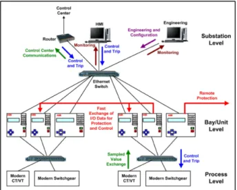
The IEC 61850 standard divides substation networks into three levels within or between which all communications take place: the process level, the bay/unit level, and the substation level. The process level includes the input/output devices, intelligent sensors and actuators; the bay/unit level includes all the protection and control devices; and the substation level includes the engineering workstation, the Human Machine Interface (HMI) and the communications equipment. Figure 2.9 presents a network topology based on the IEC61850 standard.
![Figure 2.1 - The Smart Grid characteristics and requirements [09].](https://thumb-eu.123doks.com/thumbv2/123dok_br/15956174.1098445/31.892.311.627.248.558/figure-smart-grid-characteristics-requirements.webp)
![Figure 2.2 - Principle of construction of an induction disk relay [35].](https://thumb-eu.123doks.com/thumbv2/123dok_br/15956174.1098445/37.892.262.676.107.373/figure-principle-construction-induction-disk-relay.webp)
![Figure 2.4 - Star Network Architecture [08].](https://thumb-eu.123doks.com/thumbv2/123dok_br/15956174.1098445/40.892.219.637.355.609/figure-star-network-architecture.webp)
![Figure 2.7 - Example of PRP and HSR networks coupled through Redboxes [34].](https://thumb-eu.123doks.com/thumbv2/123dok_br/15956174.1098445/43.892.292.645.104.440/figure-example-prp-hsr-networks-coupled-redboxes.webp)
![Figure 2.8 - Interconnection of a PRP network with a HSR network [34].](https://thumb-eu.123doks.com/thumbv2/123dok_br/15956174.1098445/44.892.240.611.107.420/figure-interconnection-prp-network-hsr-network.webp)
![Figure 2.9 - Substation Automation Topology [04].](https://thumb-eu.123doks.com/thumbv2/123dok_br/15956174.1098445/47.892.274.663.107.419/figure-substation-automation-topology.webp)
![Figure 2.10 - Data Structure based on Logical Nodes [04].](https://thumb-eu.123doks.com/thumbv2/123dok_br/15956174.1098445/48.892.267.589.108.419/figure-data-structure-based-on-logical-nodes.webp)
![Figure 3.1 - Station Switchyard Blueprint [44].](https://thumb-eu.123doks.com/thumbv2/123dok_br/15956174.1098445/54.892.258.595.776.1054/figure-station-switchyard-blueprint.webp)
![Table 3.1 — Switchgear - HV Panel [38].](https://thumb-eu.123doks.com/thumbv2/123dok_br/15956174.1098445/59.892.185.749.400.717/table-switchgear-hv-panel.webp)
