Luís Miguel Teixeira da Silva
Bachelor of ScienceReplication and Caching Systems for the support
of VMs stored in File Systems with Snapshots
Dissertation submitted in partial fulfillment of the requirements for the degree of
Master of Science in
Computer Science and Informatics Engineering
Adviser: Paulo Lopes, Auxiliar Professor, NOVA University of Lisbon
Co-adviser: Pedro Medeiros, Associate Professor, NOVA University of Lisbon
Examination Committee Chairperson: Prof. Carmen Pires Morgado
Raporteur: Prof. Carlos Jorge de Sousa Gonçalves Member: Prof. Paulo Orlando Reis Afonso Lopes
Replication and Caching Systems for the support of VMs stored in File Sys-tems with Snapshots
Copyright © Luís Miguel Teixeira da Silva, Faculty of Sciences and Technology, NOVA University Lisbon.
The Faculty of Sciences and Technology and the NOVA University Lisbon have the right, perpetual and without geographical boundaries, to file and publish this dissertation through printed copies reproduced on paper or on digital form, or by any other means known or that may be invented, and to disseminate through scientific repositories and admit its copying and distribution for non-commercial, educational or research purposes, as long as credit is given to the author and editor.
This document was created using the (pdf)LATEX processor, based in the “novathesis” template[1], developed at the Dep. Informática of FCT-NOVA [2]. [1] https://github.com/joaomlourenco/novathesis [2] http://www.di.fct.unl.pt
Ac k n o w l e d g e m e n t s
The work presented in this document would never see the light of day if not for the collaboration of several people to whom I wish to manifest my profound gratitude and recognition.
First I would like to thank my advisors and members of the iCBD Project, Professors Paulo Lopes, Pedro Medeiros and Nuno Preguiça, for there advice, always supporting this work and the countless hours spent trying to find the better course of action especially when I would see myself lost and overwhelmed.
It is necessary to give a special thanks to Engineer Miguel Martins from Reditus S.A, to whom I had the pleasure of work closely for more than a year. Who taught me a lot, not only from his vast knowledge of computer systems, backed by countless years of experience in the IT world and without who this work would not be possible but also for the many conversations we held in the realms of Physics, Economics and History. I will always admire how a person can keep such a large body of knowledge and a passion for sharing it.
I also like to extend my recognition to Dr. Henrique Mamede and Engineer Sérgio Rita, also from Reditus S.A., for the opportunity given, constant support and the warm-hearted welcome in my year-long stay with SolidNetworks. And, to Luís Anjos from the
Divisão de Infraestruturas Informáticas da FCT NOVA (Div-I FCT NOVA) for all his help in
resolving issues related to FCT NOVA’s internal network.
Finally, my very heartfelt gratitude to my family and friends for their unconditional support, for putting up with my grumbles when work problems went home with me, being always there with a kind word and some crazy plan to make me forget work for a couple of hours and enjoy their friendship and time spent together.
I also would like to acknowledge the following institutions for their hosting and financial support:Departamento de Informática da Faculdade de Ciências e Tecnologia of the Universidade NOVA de Lisboa (DI - FCT NOVA); the NOVA Laboratory of Computer Science and Informatics (NOVA LINCS) in particular the Computer Systems group; SolidNetworks – Business Consulting, Lda of the Reditus S.A. Group; and the funding provided through the COMPETE2020 / PORTUGAL2020 program for the iCBD project
A b s t r a c t
Recently, in a relatively short timeframe, there were fundamental changes in the way computing power is used. Virtualisation technology has changed both the model of a data centre’s infrastructure and the way physical computers are now managed. This shift is a consequence of today’s fast deployment rate of Virtual Machines (VM) in a high consolidation environment with minimal need for human management.
New approaches to virtualisation techniques are being developed at a surprisingly fast rate, leading to a new exciting and vibrating ecosystem of platforms and services. We see the big industry players tackling problems such asDesktop Virtualisation with moderate
success, but completely ignoring the computation power already present in their clients’ infrastructures and, instead, opting for a costly solution based on powerful new machines. There’s still room for improvement in Virtual Desktop Infrastructure (VDI) and devel-opment of new architectures that take advantage of the computation power available at the user’s desk, with a minimum effort on the management side; Infrastructure for Client-Based Desktops (iCBD) is one of these projects.
This thesis focuses on the development of mechanisms for the replication and caching of VM images stored in a local filesystem, albeit one with the ability to perform snapshots. In this work, there are some challenges to address: the proposed architecture must be entirely distributed and completely integrated with the already existing client-based VDI platform; and it must be able to efficiently cope with very large, read-only files, (some of them snapshots) and handle their multiple versions. This work will also explore the challenges and advantages of deploying such a system in a high throughput network, with both high availability and scalability while efficiently supporting a large number of users (and their workstations).
R e s u m o
Nos últimos anos tem-se assistido a mudanças fundamentais na forma como a capaci-dade computacional é utilizada - com o grande aumento da utilização da virtualização, tanto a forma como são geridas as máquinas físicas como os modelos de infraestruturas num centro de dados sofreram grandes alterações. Estas mudanças são o resultado da procura por uma forma de disponibilizar rapidamente VMs num ambiente altamente
consolidado e com necessidades mínimas de intervenção humana na sua gestão.
Estão a ser desenvolvidas novas abordagens às técnicas de virtualização a um ritmo nunca visto, o que leva à existência de um ecossistema altamente volátil com novas pla-taformas e serviços a serem criados a todo o momento. É possível apreciar o esforço de grandes empresas da indústria das tecnologias de informação relativamente a problemas como a virtualização de desktops - com algum sucesso, mas ignorando completamente o poder de computação que está presente nos Personal Computers (PCs) instalados, op-tando por uma via de custo elevado, baseada em máquinas poderosas. Existe ainda espaço para melhores soluções e para o desenvolvimento de tecnologias que façam uso das ca-pacidades de computação que já se encontrem presentes nas organizações, mantendo a simplicidade da sua configuração.
Esta tese foca-se no desenvolvimento de mecanismos de replicação e caching para
imagens de máquinas virtuais armazenadas num sistema de ficheiros local que tem a fun-cionalidade (pouco habitual) de suportarsnapshots. A arquitectura da solução proposta
tem de ser distribuída e integrar-se na soluçãoclient-based VDI já desenvolvida no projecto
iCBD; tem de suportar eficientemente ficheiros com vários GB (alguns deles resultantes da criação desnapshots) acedidos em leitura, e manter destes múltiplas versões. A solução
desenvolvida tem ainda de oferecer desempenho, alta disponibilidade, e escalabilidade na presença de elevado número de clientes geograficamente distribuídos.
Palavras-chave: VDI, Sistema de Ficheiros Btrfs, Snapshots, Middleware de Replicação, Servidor de Caching.
C o n t e n t s
List of Figures xiii
List of Tables xv
List of Listings xvii
Acronyms xix 1 Introduction 1 1.1 Context . . . 1 1.2 Motivation . . . 2 1.3 Project Presentation . . . 3 1.3.1 iCBD Project . . . 3 1.3.2 Previous Work . . . 4
1.4 Problem Stating and Main Contributions . . . 5
1.4.1 Replication and Caching - The Problem . . . 5
1.4.2 Main Expected Contributions . . . 6
1.5 Document Structure . . . 6
2 Research Context 9 2.1 Virtualisation . . . 10
2.1.1 Hypervisors . . . 10
2.1.2 Virtual Desktop Infrastructure . . . 12
2.1.3 Virtual Machine Image Storage . . . 16
2.2 Storage . . . 18 2.2.1 Storage Challenges . . . 18 2.2.2 File Systems . . . 19 2.2.3 Snapshots . . . 20 2.3 Caching . . . 21 2.4 Replication . . . 22
3 iCBD - Infrastructure for Client-Based Desktop 23 3.1 The Concept . . . 24
3.2.1 iCBD Machine Image . . . 25
3.2.2 Boot Services Layer . . . 28
3.2.3 Administration Layer . . . 29
3.2.4 Client Support Layer . . . 31
3.2.5 Storage Layer . . . 31
4 Implementation of the iCBD-Replication and Cache Server 33 4.1 Motivation and System Architecture . . . 34
4.2 Implementation of a Replication Module . . . 35
4.2.1 Requirements . . . 35
4.2.2 System Overview . . . 37
4.2.3 Communications between nodes . . . 39
4.2.4 Name Server . . . 43
4.2.5 Image Repository . . . 43
4.2.6 Master Node . . . 46
4.2.7 Replica Node . . . 49
4.3 Deploying an iCBD Platform with a Cache Server . . . 51
4.3.1 The iCBD infrastructure at DI - FCT NOVA . . . 51
4.3.2 Roles in the Platform . . . 53
4.3.3 Installing iCBD Core Services . . . 55
5 Evaluation 59 5.1 Experimental Setup . . . 60
5.2 Metodology . . . 61
5.3 Replication Service Benchmark . . . 62
5.4 Cache Server Performance Benchmark . . . 64
6 Conclusions & Future Work 71 6.1 Conclusions . . . 71
6.2 Future Work . . . 72
Bibliography 73 I iCBD-Replication Documentation 79 II iCBD Installation Guide 105 III Bug on Btrfs affecting CoreUtils tool 123 III.1 Bug Report . . . 123
III.2 Resolution . . . 124
L i s t o f F i g u r e s
2.1 Virtualization architecture with type 1 and type 2 hypervisors . . . 11
2.2 An exemple of a Virtual Desktop Infrastructure, adapted from AppDS . . . . 13
2.3 Conceptual overview of DaaS architecture, adapted from Intel . . . 16
3.1 iCBD Layers View . . . 25
3.2 iCBD Machine Image Files . . . 26
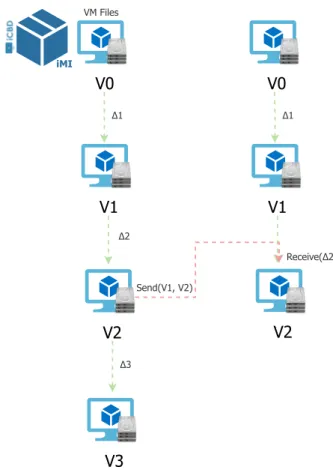
3.3 iMI Life Cycle inside the iCBD Platform . . . 27
4.1 iCBD Replication and Caching Architecture (high-level) . . . 34
4.2 iCBD iMI Snapshots Structure . . . 36
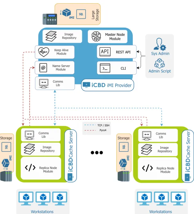
4.3 iCBD Replication Modules and Communications . . . 37
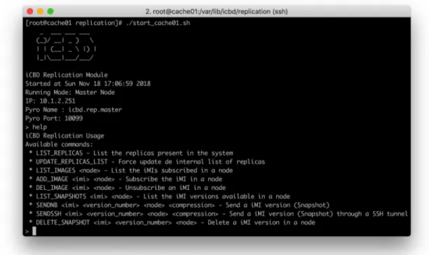
4.4 iCBD Replication Module help output . . . 47
5.1 iCBD Nodes and Networking Setup . . . 61
5.2 Mean Boot Time of five workstations using iSCSI (Sequential Boot Scenario), comparing iMI provider and network speed . . . 66
5.3 Mean Boot Time of five workstations using NFS (Sequential Boot Scenario), for different iMI providers and network speeds . . . 66
5.4 System metrics for iCBD-imgs on one run of the five workstations sequential boot scenario test . . . 67
5.5 System metrics for iCBD-Cache02 on one run of the five workstations sequen-tial boot scenario test . . . 68
5.6 System metrics for one run on the iCBD-Cache02 in a boot storm scenario . . 69
5.7 Boot Time of fifteen workstations simultaneously (Boot Storm Scenario) for different iMI providers and network speeds . . . 69
L i s t o f Ta b l e s
4.1 Specifications of one HP ProLiant DL380 Gen9 host . . . 52
4.2 Specifications of the HPE MSA 2040 SAN Storage . . . 52
4.3 Specifications of all Networks . . . 53
4.4 Specifications of the virtual hardware of the iCBD machines . . . 54
4.5 Specifications of the Physical Cache Server . . . 55
5.1 Specifications of the Laboratories Workstations . . . 60
5.2 Physical infrastructure of the FCT NOVA and SolidNetworks sites . . . 60
5.3 Time spent and data transmitted on transferring a complete iMI from Master to Replica . . . 63
5.4 Time spent and data transmitted on transferring a delta between v1 and v2 of an iMI from Master to Replica . . . 64
5.5 Total data received in the user workstation after booting, depending on boot protocol and iMI providers . . . 65
5.6 Comparison of boot times in a boot storm situation in both providers (iCBD-imgs and iCBD-cache02) . . . 68
L i s t o f L i s t i n g s
1 Dependences of the iCBD-Replication module bundled in a Pipfile . . . . 40
2 Starting procedure of a Name Server . . . 44
3 Example of the information stored in theicbdSnapshot object. . . . 45
4 iCBD-Replication REST API Route Mapping . . . 50
5 Strace of thecp --reflink=always command . . . 125
Ac r o n y m s
API Application Programming Interface.
BIOS Basic Input/Output System.
CLI Command Line Interface.
CoW Copy-on-Write.
CPU Central Processing Unit.
DaaS Desktop as a Service.
DC Data Centre.
DHCP Dynamic Host Configuration Protocol.
FAT File Allocation Table.
FS File System.
HTTP Hypertext Transfer Protocol.
IaaS Infrastructure as a Service.
iCBD Infrastructure for Client-Based Desktop.
iMI iCBD Machine Image.
IP Internet Protocol.
iSCSI Internet Small Computer Systems Interface.
IT Information Technology.
KVM Kernel-based Virtual Machine.
LAN Local Area Network.
NFS Network File System.
NVRAM Non-Volatile Random-Access Memory.
OS Operating System.
PC Personal Computer.
PXE Preboot Execution Environment.
RAID Redundant Array of Independent Disks.
RAM Random-Access Memory.
RCS Replication and Caching Service.
RDP Remote Desktop Protocol.
RDS Remote Desktop Services.
REST Representational State Transfer.
RFB Remote Framebuffer Protocol. RPC Remote Procedure Call.
SSH Secure Shell.
TCP Transmission Control Protocol.
TFTP Trivial File Transfer Protocol.
UDP User Datagram Protocol.
VDI Virtual Desktop Infrastructure.
VLAN Virtual Local Area Network.
VM Virtual Machine.
C
h
a
p
t
e
r
1
I n t r o d u c t i o n
1.1
Context
The concept of virtualisation, despite all the recent discussion and hype, isn’t new: the technology has been around since the 1960s [11], but it was not until it was available for the x86 architecture [2] and, later on, further developed with the introduction of Intel VT [47] and AMD SVM [24] in the 2000s, that virtualisation has entered the mainstream as a must-have technology for server deployment across any production environments.
With efficient techniques that take advantage of all available resources, and continu-ously lowering price points on hardware, an opportunity for the advance in application architecture and a revamp in the supporting infrastructure was at hand.
However, companies realised that the cost to run an in-house, fully fledged data centre (DC) may be, in some cases, unreasonable, and that building and managing it is also a cumbersome task. And, cost is high - not as a consequence of hardware costs, but when factoring in all other parcels: cooling systems that extract the heat generated by servers, storage and networking, physical security to protect the DC, fire suppressing systems and, the largest factor, cost of manpower to maintain the infrastructure; when all these parcels are added together, the result is a high value for OPEX (operational expenditures).
To further aggravate costs, demand for instantaneous access to information coupled with an ever-increasing amount of data to handle also demands a level of resources that continues to grow every day.
This created an opportunity for the Infrastructure as a Service (IaaS) [38] cloud model that, in the case of public clouds, outsources all the resource provisioning to third parties, which are (must be) experts in maintaining very large data centres, geographically dis-persed across the globe (for high availability), and can benefit from high discounts from suppliers (hardware, energy, etc.).
With major industry players building their own, very large DCs, and offering both public and hybrid cloud services, supporting more and more types of services with an increasing number of customers, new ways to store data have emerged, and distributed object storage is the platform that supports other storage paradigms – files, databases, key-value stores, etc. – that exhibit high degrees of reliability, consistency, performance, scalability, all essential to a broad range of applications with different workloads.
But, as always, there’s no one size fits all solution, and clouds are no exception: some environments have peculiarities – such as low latency, and the cost to keep it under control – that dictates that computing resources must be close to the user; one of these environments is Desktop Virtualisation. VDIs, i.e., Virtual Desktop Infrastructures, are computing infrastructures that provide their users with a virtual desktop: when the user pics his/her workstation (usually PC or laptop) and interacts with it, the desktop application (e.g., Windows Desktop, CentOS Gnome, Ubuntu Unity) displayed at the device’s screen is not running natively on the user’s workstation. It is running in a Virtual Machine (VM).
This is the umbrella (context) of our thesis/project: an infrastructure that runs VMs that act as the user’s “personal computer” and that he/she can access anywhere where a network is available (subject, naturally, to security and performance constraints), using another computer for that task. The remainder of this chapter will provide more details but, for now, we want to add that previous work was researched and developed a VDI, named iCBD, that is running and functionally “complete”. Our task is to provide features that will bring fault-tolerance, high-availability and scalability to the solution (with an eye on cost).
1.2
Motivation
Virtualisation is the pillar technology that enabled the widespread availability of IaaS cloud providers, benefiting of economies of scale. These cloud providers, such as Amazon AWS [7], Microsoft Azure [39] and Google Cloud Platform [20], manage thousands of physical machines all over the globe, with the vast majority of their infrastructures being multi-tenant oriented.
The sheer magnitude of those numbers leads to an obvious problem, i.e., how to store all this data efficiently. And, not only there is the need to store customer’s generated data but also to manage all the demands of the infrastructure and the multitude of services offered. One approach taken by these companies was the development of their proprietary storage solutions. For instance, Google uses BigTable distributed storage system [12], to store application-specific data, and then serve it to users. This system relies on the Google File System underneath to provide a robust solution to store logs and data files and was designed to be reliable, scalable and fault tolerant.
One characteristic in particular that stands out and is present in many of today’s very large storage infrastructures is the use of snapshots with copy-on-write (CoW) techniques.
1 . 3 . P R O J E C T P R E S E N TAT I O N
The adoption of such mechanisms allows for quick copy operations (a.k.a. cloning) of large data sets while saving resources and, at the same time, providing transparent con-current operations as read-only versions of the data always ready for use – e.g., to perform backups - while applications simultaneously execute write operations on their snapshots. But large storage infrastructures are distributed; hence, the other important mechanisms are replication, and data distribution: the duplication of records across multiple ma-chines, serves not only as a “security net”, in case of a fault (as duplication removes the single point-of-failure characteristic), but can also be used to take advantage of net-work bandwidth (as one can spread a single access across multiple servers, i.e., accessing several “duplicate segments”).
While the above discussion was focused on distributed storage systems, some of these features, namely snapshots, are also available in non-distributed file storage implemen-tations. One of these recently developed systems that has a significant adoption in the Linux community is Btrfs [48].
Btrfs, whose name derives from B-tree data structures, was designed with two goals: support snapshots and maintain excellent performance in a comprehensive set of condi-tions. We, bounded by the iCBD’s project goals, claim that the combination of Btrfs with replication and partitioning techniques opens up the way to a more advanced solution that serves the needs of an up-to-date storage system, and be easily integrated into an existing platform, serving a vast number of clients and presenting very good performance.
1.3
Project Presentation
This dissertation work was performed in the context of a more comprehensive project, named Infrastructure for Client-Based Desktops (iCBD) [36]. The iCBD project is being developed in collaboration between theNOVA LINCS Research Center, hosted at DI - FCT NOVA, and SolidNetworks – Business Consulting, Lda., a subsidiary of Reditus S.A..
The project’s primary objective is to develop a winning VDI product that separates itself from the current solutions (that we have dubbed server-based VDI), which execute the virtual desktops in large, resource-heavy, servers. iCBD’s approach, which we dubbed client-based VDI, supports the execution of both native (Linux only) and virtual desktops (any “virtualisable” OS) on the user’s physical computer, in a nonintrusive way.
1.3.1 iCBD Project
There are some leading-edge aspects of the Infrastructure for Client-Based Desktop project which sets it apart from other existing ones such as the adoption of a diskless paradigm with a remote boot, the way the platform stores Virtual Machine images, and the support for virtualised or native execution on the target workstation1, depending on
1In this document workstation is a user’s desktop PC, laptop, etc., any PC compatible computing device with a recent enough architecture that support modern hypervisors.
the user’s choice. [35]
The remote boot of the user’s workstation requires the cooperation of HTTP, TFTP, DHCP and the image repository servers - the ones that store both read-only VM templates and writable space for running instances started from those templates. Communication between workstations and the platform is over the HTTP protocol, providing both flexi-bility and efficiency. [3, 35, 37]
In short, the primary objectives of the project are:
• Offering a work environment and experience of use so close to the traditional one that there is no disruption for the users when they begin to use this platform.
• Enabling centralised management of the entire infrastructure, including servers, in their multiple roles, storage and network devices, all from a single point.
• Completely decouple users and workstations in order to promote mobility.
• Support disconnected operation of mobile workstations.
When all these objectives are taken into account, there is a clear distinction from other solutions currently (and previously) available. As far as we know, no other solution is so comprehensive in the use of the resources offered by the physical workstations whether they are PCs, laptops or similar devices.
1.3.2 Previous Work
The iCBD project started about two years ago, and there has been a lot of work in that period, namely by DI - FCT NOVA students. Previous work was focused on the creation of the instances of virtual machines, using either the storage system’s snapshot mechanisms (for those where native snapshots were available) or the hypervisor’s own mechanism. These studies resulted in two MSc dissertations, one carrying out a more in-depth study of Btrfs (and other file systems) while the other focused itself in object-based storage, particularly on the Ceph (RADOS) product.
These two avenues, file system and object-storage system, proved themselves well suited for the iCBD project, and resulted in the next step, namely on how to support a multi-node, scalable, and failure-tolerant iCBD infrastructure, one where nodes may be geographically dispersed.
1 . 4 . P R O B L E M S TAT I N G A N D M A I N C O N T R I B U T I O N S
1.4
Problem Stating and Main Contributions
This dissertation aims to build upon the previous contributions, deeply study the core of the iCBD platform, and tackle the next set of questions, mainly:
• In a geographically dispersed, multi-server iCBD infrastructure, how do we keep the VM templates consistent and available even on the presence of network faults?
• How do we keep a simple management interface in a distributed platform?
• How to scale the platform in order to handle a large number of clients and maintain or even enhance its performance?
1.4.1 Replication and Caching - The Problem
To address the previous questions, we start with a known fact: providing high availability for data requires redundancy, and the simplest way to provide redundancy is to have replicas. Therefore, building a replication mechanism is clearly our starting point. With that in mind, we tackle a second part of the problem: if we want to provide to the iCBD clients (workstations) fast access to the data, that data must be moved, or cached, near those clients. Now, if our cache stores the full data objects that the client needs, and not just parts of those objects, caching becomes just a side-effect from replication.
Establishing Goals Providing a mechanism that ensures the correct replication of data between nodes of the platform is of paramount importance; but other objectives, such as achieving the best performance possible on data transfer operations – that is, transfer speed must be maximised, and the amount of data moved around should be minimised, and the process should not be computationally intensive – are also important. Another goal is ease of integration of the replication process with multiple technologies: the iCBD storage layer is open to different storage backends – we already mentioned Btrfs and Ceph. So, the design of the replication module should strive for an API that eases the in-tegration with different backend technologies, as long as these do provide a snapshotting mechanism.
As far as caching is concerned, two problems must be addressed: how to plan the number and location of cache (i.e., replica) servers, and which platform services are fun-damental for running images on the user’s workstations and how can they be integrated with the replication and caching infrastructure in order to deliver the best possible expe-rience to the highest number of clients.
To summarise, the following list expresses the key requirements that must drive the architecture, design, planning and execution of (the rest of) our work:
• The iCBD platform needs to be always available and maintain top-notch perfor-mance in multiple locations, while serving a considerable number of clients.
• There are two main reasons for data replication: fault-tolerance (replicas represent backups) and moving data closer to the clients.
• Taking for granted that data is close to the consumer, devise ways to deliver that data (to the client) as efficiently as possible.
• Booting a client should require the smallest number of platform functionalities possible, simplifying the boot process near the consumer.
1.4.2 Main Expected Contributions The main expected contributions are:
• Perform a thorough analysis of the iCBD platform layers and modules that are already implemented, in order to understand its internals, to document it and allow an efficient planning of the remaining of our work.
• Study, develop, and evaluate an implementation of a distributed and replicated storage platform to support VMs, built on top of Btrfs.
• Implement a client-side caching solution in order to increase availability, improve response time, and enable better management of resources.
• Integrate the solutions described above with the previous work and the existing infrastructure.
• And, finally, carry out a series of tests that a) allow us to assert that our replication and caching system is functionally complete and stable enough for production use, b) allows us to draw meaningful conclusions about its performance, and c) provide us with hints for future enhancements of the iCBD platform.
1.5
Document Structure
The rest of the document is structured as follows:
• Chapter 2 Research Context - This chapter presents existing technologies and
theo-retical approaches which were studied; examples include storage systems and their features, and details on virtualisation techniques and hypervisors.
• Chapter 3 iCBD - Infrastructure for Client-Based Desktop - In this chapter, we
present the iCBD platform: we start with an overview of the solution, describe the multiple layers and explains the conceptual and architectural decisions that were made. This chapter is essential to the understanding of the bigger picture and where our work fits in.
1 . 5 . D O C U M E N T S T R U C T U R E
• Chapter 4 Implementation of the iCBD-Replication and Cache Server - We start
with an in-depth view of the implementation of the iCBD Replication module, detailing the architectural decisions and the implemented components. Then, a description is given on the efforts to build, on the FCT NOVA campus, a server infrastructure exclusively dedicated to the iCBD project. Then we explain how to build and deploy the iCBD Cache Server software for a node that will support a student’s computer lab with 15 workstations in the Computer Science Department.
• Chapter 5 Evaluation - In this chapter, we present the evaluation process employed
to validate our Implementation, with an emphasis on the analysis of the results we obtained and a comparison with the baseline values.
• Chapter 6 Conclusions & Future Work - This chapter concludes the dissertation;
we provide the answers to the questions we raised in the Introduction, summarise the results achieved in the evaluation process, and recall some ideas for further improvements, ones that were formulated during the implementation process, and we believe are a good starting point for future work.
C
h
a
p
t
e
r
2
R e s e a r c h C o n t e x t
The focal point of this dissertation is the implementation of a scalable and coherent distributed data store on top of a set of local (and independent) file systems. The file systems, however, are not used for “general purpose” work: in our deployment, they store VMs - (1) their read-only base images (or templates) and / or (2) their running instances backstores and / or (3) their “support files” (VM specifications, Non-Volatile Random-Access Memory (NVRAM) / Basic Input/Output System (BIOS) images, etc). Furthermore, the target file systems are those which are able to natively provide snapshots and, for the purpose of this dissertation our choice was Btrfs.
Moreover, our work should integrate smoothly into a broader infrastructure illus-trated in detail in Section 3. In this chapter, we start with a survey of core concepts directly associated with the thesis and compliment with some analysis on the state-of-art in the relevant fields. The organisation of this chapter is as follows:
Section 2.1 overviews virtualisation as a core concept, describing significant properties and the inner works of hypervisors and finishes with a comprehensive discussion about the multiple VDI models.
Section 2.2 studies the principal challenges for a storage system in a VDI context and makes a survey of the multiple types of file systems which are currently prevalent in a data centre environment.
Section 2.3 talks about the problem of the locality of the data, and how that fact can influence the performance and scalability of a system.
Section 2.4 expands on the fact that storing data in a single location is not enough for compliance with current requirements, such as high availability, fault tolerance and performance standards in critical systems.
2.1
Virtualisation
Most of today’s machines have such a level of performance that allows the simultaneous execution of multiple applications and the sharing of these resources by several users. In this sense, it is natural to have a line of thought in which all available resources are taken advantage of efficiently.
Virtualisation is a technique that allows for the abstraction of the hardware layer and provides the ability to run multiple workloads on a shared set of resources. Nowa-days, virtualisation is an integral part of manyIT sectors with applications ranging from
hardware-level virtualisation, operating system-level virtualisation, and high-level lan-guage virtual machines.
A Virtual Machine, by design, is an efficient, isolated duplicate of a real machine [44], and therefore should be able to virtualise all hardware resources, including processors, memory, storage, and network connectivity.
For the effort of managing the VMs, there is a need for a software layer that has specific characteristics. One of them is the capability to provide an environment in which VMs conduct operations, acting both as a controller and a translator between the VM and the hardware for all IO operations. This piece of software is known as a Virtual Machine
Monitor (VMM).
In today’s architectures, a modern term was been coined, theHypervisor. It is common
to mix both concepts (VMMs and Hypervisors), as being the same, but in fact, there are
some details that make them not synonymous. [2]
2.1.1 Hypervisors
The most important aspect of running a VM is that it must provide the illusion of being a real machine, allowing to boot and install any Operating System (OS) available for the real hardware. It is the VMM which has that task and should do it efficiently at the same time providing this three properties [44]:
Fidelity: a program should behave on a VM the same way or in much the same way as if it were running on a physical machine.
Performance: the vast majority of the instructions in the virtual machine should be exe-cuted directly by the real processor without any intervention by the hypervisor.
Isolation: the VMM must have complete control over the resources.
A hypervisor is, therefore, both an Operating System and a Virtual Machine Monitor. It can be deployed on top of a standard OS, such asLinux or Microsoft Windows, or in a
bare metal server.
To start a VM, the hypervisor kernel spins up a VMM, which holds the responsibility of virtualising the architecture and provide the platform where the VM will lie. Thus,
2 . 1 . V I R T UA L I S AT I O N
since the VM executes on top of the VMM, there is a layer of separation between the VM and the hypervisor kernel, with the necessary calls and data communications taking place through the VMM. This feature confers the necessary degree of isolation to the system. With the hypervisor kernel taking care of host-centric tasks such asCPU and memory
scheduling, and network and storage data movement, the VMM assumes responsibility to provide those resources to the VM.
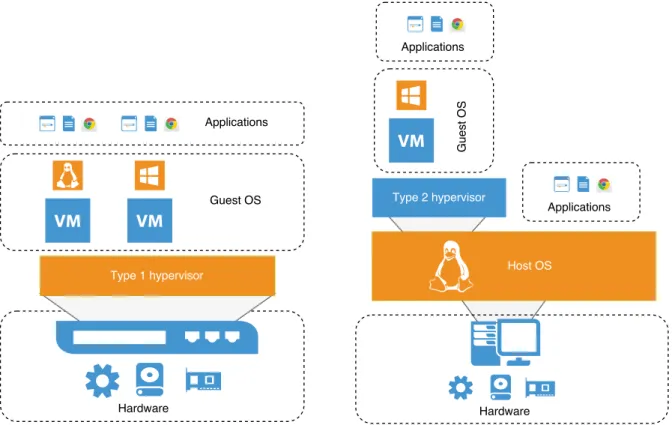
An hypervisor can be classified into two different types [8], depicting two virtualisa-tion design strategies, as shown in Figure 2.1:
Figure 2.1: Virtualization architecture with type 1 and type 2 hypervisors
Type 1 hypervisor: Sometimes referred as a bare-metal hypervisor, since there is no need to rely on a host operating system, as it runs directly on the hardware. Moreover, it is the only program executed by the CPU in its most privileged mode. As there isn’t any layer between the hypervisor and the resources, this type of hypervisor presents a more efficient solution than the Type 2.
In addition to the improved performance provided by the sharing or partitioning of devices between the several guest VMs, this architecture provides the benefit of supporting the execution of real-time OSs. The low-level nature of these hypervisors with the broad access to the hardware has proven useful for use-cases that need to deploy a multiplicity of operating systems even in mission-critical circumstances.
Recognising all the facts above, we can point that there are also some disadvantages. Any drivers needed to support different hardware platforms must be covered by the hypervisor package.
Type 2 hypervisor: This second variant of the hypervisor model relies on an already in-stalled operating system and acts very similarly to any conventional process. Here, the hypervisor layer is a union of a host operating system with specialised virtu-alisation software, including extensions to that OS kernel, that will manage the guest VM. In this case, the hypervisor makes use of the services provided by the OS, which leads to a more significant memory footprint when compared to Type 1 but is integrated seamlessly with the remainder of the system. An excellent illustration of this kind of paradigm is Oracle VirtualBox and VMware Workstation/Fusion [2].
In this architecture, the host operating system retains ownership of the physical components, with each VM having access to a confined subset of those devices, and the virtual machine monitor providing an environment that emulates the actual hardware per VM.
All the above culminates in some advantages: Type 2 hypervisors are regularly deployed on desktop and laptop class of hosts, allowing: simulation of a rather com-plex testing virtualised systems without the expense and comcom-plexity of managing dedicated hardware; seamless integration with a graphical environment; host-guest file and print sharing.
Either way, the challenge lays in the fact that the hypervisor needs to provide to guest OS a safe execution environment and at the same time create different machine configu-rations to each one of them. These characteristics, such as the number and architecture of virtual CPUs (vCPU), the amount and type of memory available (vRAM), the allowed space to store files (vDisk), and so on, are user configurable but it is the job of the hyper-visor to do all the resource management. The settings of these individual components reside in a VM configuration file. In the case of VMware hypervisors, the file has the.vmx extension,[45, 60] while in a KVM environment, that configuration is stored in a.xml file. [13]
With a virtualised infrastructure there is an opportunity for a substantial reduction in the number of servers which, in turn, diminishes the setup time as those VMs are, in a broad manner, created simply by cloning techniques. Software updates can be hugely simplified and made available to all VMs at once if those VMs are created on-demand from up-to-date templates at the beginning of a user session.
2.1.2 Virtual Desktop Infrastructure
It is common to find in a typical midsize corporate infrastructure hundreds of servers and thousands of workstations. All in a diverse ecosystem counting with many hardware
2 . 1 . V I R T UA L I S AT I O N
Linked Clones Centralized
VirtualDesktops Entreprise Services Master Image Administration Clients Storage Switch Blade PCs Terminal Servers Physical PCs
Figure 2.2: An exemple of a Virtual Desktop Infrastructure, adapted from AppDS [9]
configurations, different OSs and applications needs. Probably even supporting several versions of the same software is required for the day to day operations.
Organisations struggle daily with the traditional problem of installing software in local workstations disks one-by-one (even if employing an automated process). This task tends to be daunting as a company escalates in size and leads to some other predicaments:
• A Systems Administrator and IT Staff burden with significant infrastructure admin-istration responsibilities and technical skills.
• A delay on the installation or reinstallation of new software and recovery from breakdowns or administration mistakes, which in large installations such interven-tion could take days.
• Installation processes may consume much of the available bandwidth in a network, so if this job is to be executed simultaneously on several workstations, it tends to be scheduled to off work hours to avoid disturbances.
• Periodical software updates (such Microsoft’s famous Patch Tuesdays [42]) are or-dinarily released in the morning’s first boot of a workstation, which can bloat the traffic and render useless the workstation for the remainder of the update period. • If an update proves to be undesirable, by introducing some unexpected behaviour,
it is quite difficult to reverse this situation, which may even demand a new configu-ration infrastructure-wise.
One solution to the unpleasant situations outlined above is to minimise the footprint of installed software and reduce its managing needs. It is possible to conceive all the
software required to run a workstation (Operating System and applications) packaged in a single unit like a Virtual Machine. This mechanism allows for the virtualisation of a workstation that can be executed either locally on a typical PC / Laptop, or on a server. The most relevant approach and with more expression at the moment is the Virtual Desktop Infrastructure (VDI).
The concept encompasses a series of techniques, providing on-demand availability of desktops, in which, all computing is performed employing virtual machines [25]. Typi-cally this solution offers a centralised architecture, where users desktops run in VMs, the user’s environment resides on a server in a data centre, as shown in Figure 2.2. However, other components are required, such as storage for the users and VMs data and a network capable of moving large data blocks quickly, all in a perspective where from the user’s viewpoint there can’t be any apparent difference between a virtual desktop and a local installation.
There are two antagonistic approaches to the architecture, one focused on the server-side and the other on the client-server-side but both solutions are in an in-house paradigm were all configurations, management and storage needs are the responsibility of the business IT staff. A third approach emerged in recent years, with the peculiarity of being cloud-based, coined Desktop as a Service. In this section, we present a summary of the technologies above-mentioned.
Server-based VDI This is the most common approach, in which the VM runs remotely on a server through a hypervisor. In this model, the images for the virtualised desktops remain deposited in a storage system within a Data Centre. Then, when the times comes for the execution of such VM, a server that is running a hypervisor provisions the VM from storage and puts it into action. Featuring such benefit, as the fact that only a low-performance thin client with support for a protocol such as Remote Desktop Protocol (RDP) [46] or the Remote Framebuffer Protocol (RFB) [55] is required to interact with the virtual desktop.
The downside involves the costs necessary to maintain the service. Highly capa-ble support infrastructure is needed (computing, storage, networking and power). With the additional requirement, of a need in some use cases, for adding high-end graphics processors to satisfy the workflow of customers using multimedia tools. We can still observe that the totality of the computing capacity of the hardware already present in the premises of a client prevails not harnessed. Of course, the machines already present can continue to be used, since they naturally have the resources to use the tools mentioned above, but the non-use of their full potential makes for all past investment made in hardware that pointless.
There are plenty of commercial solutions that use this principle, with the three most significant players being VMware’s Horizon platform [58], XenDesktop from Citrix [62] and Microsoft with Microsoft Remote Desktop [41].
2 . 1 . V I R T UA L I S AT I O N
Client-based VDI In this model, the VM that contains the virtual desktop is executed directly on the client’s workstation. This machine makes use of a hypervisor that will wholly handle the virtual desktop.
Since all computing work predominates on the client side, the support infrastruc-ture (as far as servers are concerned) in this model as a much smaller footprint, having only as a general task to provide a storage environment. Alternatively, all the data could be already locally present in the hard drives of the clients, almost disowning the servers to sheer administration roles and the maintenance of other services.
The advantages remain close to the previous solution, with the added benefit of a reduced need for resources and the possibility of using some already present in the infrastructure. Although this approach presents itself as significantly more cost restrained, there isn’t a notable adoption by software houses in developing products in this family. Reasons for this fact can be attributed to the implementation of such solutions that required a more complicated process, sometimes claiming the complete destruction of locally stored data on workstation hard disks. [14]. An example is a previously existing solution by Citrix, the XenClient [62].
Desktop as a Service The third, and most modern, concept incorporate the VDI archi-tecture with the made fashionable cloud services. In some aspects shows some astonishing similarities to the server-based method, where servers drive the compu-tation, but here, the infrastructure, the resources and the management efforts are located in the midst of a public cloud. An example of this design pattern is shown in Figure 2.3.
The points in favour are some: There is good potential for cost reduction in the field of purchase and maintenance of infrastructure since those charges are imposed on third parties. Every subject related to data security is also in the hands of the plat-form providers. Enables what is called zero clients, an ultrathin client, typically in a small box form factor, which the only purpose is to connect the required periph-erals and rendering pixels onto the user’s display. [63] With the added benefit of presenting very competitive costs per workstation when compared to other types of clients (thick and thin clients) and a reasonable saving on energetic resources.
However, in contrast, the downsides are also a few. Since the data location fre-quently is in a place elsewhere from its consumption, some bandwidth problems can arise, limiting the ability to handle a large number of connections. Adding to this mix is the issue of the unavoidable latency, a result of the finite propagation speed of data, which tends to escalate with the distance required to advance. Also, there is the jitter factor, caused by latency variations, which are observed when connections need to travel great lengths through multiple providers with different congestion rates. All these facts not only may lead to a cap on the numbers of clients
that are able of connecting simultaneously but also can be a motive in a diminished experience and quality of service provided, when in comparison to the previously presented solutions.
Cl
oud
Figure 2.3: Conceptual overview of DaaS architecture, adapted from Intel [30]
In this new field, a multitude of solutions is emerging with public cloud providers leading the way. Amazon in its AWS portfolio delivers Amazon Workspaces [6], and Microsoft implements the RDS features [40] on the Azure product line. Nev-ertheless, there are also some smaller contenders, as an example, Workspot [61] (a company founded by ex-Citrix employees) makes use of the Microsoft Azure Cloud to provide there take on cloud-native Virtual Desktops.
2.1.3 Virtual Machine Image Storage
The data storage is one of the focal points to address in this work. Therefore, it is mean-ingful to understand how a virtual machine is composed and how is translated to a representation in a storage device.
The basic anatomy of a Virtual Machine encompasses a collection of files that define the VM settings, store the data (i.e. Virtual Disks) and save information about the state of its execution. All of these data and metadata need to be deposited on storage devices of whatever type.
VMware Architecture Given the architecture presented by VMware software [60], the main files required for the operation of a VM are:
• The VM configuration file - The .vmx file holds the primary configuration options,
defining every aspect of the VM. Any virtual hardware assigned to a VM is present here. At the creation time of a new virtual machine, the configurations regarding the guest operating system, disk sizes, and networking are appended to the .vmx
2 . 1 . V I R T UA L I S AT I O N
file. Also, whenever an edit occurs to the settings of a virtual machine, this file is updated to reflect those modifications.
• The virtual disk files - Embodying multiple.vmdk, which stores the contents of the
virtual machine’s hard disk drive and a small text disk descriptor file. The descriptor file specifies the size and geometry of the virtual disk file. Also includes a pointer to the full data file as well as information regarding the virtual disks drive sectors, heads, cylinders and disk adapter type. The virtual disk actual data file is conceived while adding a virtual hard drive to a VM. The size of these files will fluctuate based on the maximum size of the disk, and the type of provisioning employed (i.e. thick or thin provisioning)
• The file that stores the BIOS - The.nvram file stores the state of the virtual machine’s
BIOS.
• The suspended state file - The .vmss contains the state of a suspended virtual
ma-chine. This file is utilised when virtual machines enter a suspended state giving the functionality of preserving the memory contents of a running VM so it can start up again where it left off. When a VM is returned from a suspend state, the contents of this file are rewritten into the physical memory of the host, being deleted in the event of the next VM Poweroff.
• Log files - A collection of.log files is created to log information about the virtual
machine and often handled for troubleshooting purposes. A new log file is created either during a VM power off and back on process, or if the log file stretches to the maximum designated size limit.
• The Swap file - The vswp file warehouses the memory overflow in case the host
cannot provide sufficient memory to the VM, and Ballooning technique cannot be employed to free memory [27]
In addition to the records described above, there may be some more files associated with the use of snapshots. More concretely, a.vmsd file and multiple .vmsn. The first is a file with the consolidation of storing and metadata information about snapshots. The other one, represents the snapshot itself, saving the state of the virtual machine in the moment of the creation of the snapshot.
The implementation of snapshots mentioned above applies to a specific implemen-tation of VMware and takes form as follows: first, the state of the resource is stored in the form of an immutable and persistent object. Then, all modifications that transform the state of the resource are gathered in a different object. The diverse snapshotting techniques are addressed in a more comprehensive sense in the Section 2.2.3.
2.2
Storage
As stated in previous sections, the main problem to be addressed in this work is the storage concerning virtual machines. That could be either images, snapshots, files or data structures that are needed to support the execution of a VM.
When applied to the VDI concept some demands appear in the form of specific care needed at planning the storage system architecture, as well as the supporting infrastruc-ture: the hardware picked, network topology, protocols used, and software implemented. At the end of the day, the idea is to present a solution that offers an appropriate cost to performance ratio, and that with little effort can scale when the need emerges.
2.2.1 Storage Challenges
I/O Storms In a typical data centre application, with a well-designed infrastructure and in normal conditions, the storage system is steadily used but isn’t being stressed continuously with I/O requests that directly affect the system performance. However, that postulate is no longer valid when talking about the storing of VM files for use in a VDI environment. In this type of context, some events can cascade in I/O storms that eventually introduce degradations in storage response time, which diminishes the performance of the overall system and in turn leads to a lower satisfaction level for the users of said system. From several events that influence a storage system we can point out some that have more expression in a VDI setting:
Boot Storm It may happen, on the occasion of the starting a work shift; with several users simultaneously arriving at their desk and booting their workstations. In this circumstance, all VMs are simultaneously performing multiple read and write oper-ations on the storage system, which translates into poor response times and a long wait for the end of the boot process.
Login Storm Right after the booting an OS, the workstations are not entirely operational users have to log in to access a desktop, including applications and files. This pro-cedure, results in a considerable number of concurrent I/O requests from multiple VMs in a short time, as the system attempts to load quite a few files related to the user’s profile.
Malware and Anti-Virus Software Scanning Usually scans for unwanted files and un-trusted applications, are scheduled to execute at a time when they cause the least possible impact taking into consideration the load of the machine. However, it is not uncommon to observe a behaviour where this kind of software starts a scan right after boot. Alternatively, the unfortunate case where different machines de-cide to start that examination at the same time, causing a negative impact on every machine.
2 . 2 . S T O R AG E
Big Applications Needs Some applications can be very I/O intensive, like loading a project in an IDE with numerous libraries and dependencies that need to be re-viewed at startup. Also, we can envision a scenario where multiple users simultane-ously open the same very resource intensive application, for instance, in a classroom, the teacher asks the students to start a particular application, the I/O requests to the storage system will most likely be simultaneous.
Operating System Updates Similarly to Malware and Anti-Virus Software Scanning, the update process of an Operating System will most likely be tied to a schedule that is based on the current load of a machine. Yet, multiple systems may decide to perform an update in the same space of time thus leading to the bottleneck problem of concurrent access to the storage system.
2.2.2 File Systems
The traditional and perhaps most common way of storing files and, in turn, VMs is the use of file systems. This kind of system is used to manage the way information is stored and accessed on storage devices. A file system can be divided into three broad layers, from a top-down perspective we have:
• The Application Layer is responsible for mediating the interaction with user’s ap-plications, providing an API for file operations. This layer gives file and directory access matching external names adopted by the user to the internal identifiers of the files. Also, manages the metadata necessary to identify each file in the appropriate organisational format.
• Then the Logic Layer is engaged in creating a hardware abstraction through the creation of logical volumes resulting from the use of partitions, RAID volumes, LUNs, among others.
• The last one is the Physical Layer. This layer is in charge with the physical opera-tions of the storage device, typically a disk. Handling the placement of blocks in specific locations, buffering and memory management.
There are many different types of file systems, each one boasting unique features, which can range from security aspects, a regard for scalability or even the structure followed to manage storage space.
Local file systems: A local filesystem can establish and destroy directories, files can be written and read, both can move from place to place in the hierarchy but everything contained within a single computing node. Good performance can be improved in certain ways, incorporating caching techniques, read ahead, and carefully placing the blocks of the same file close to each other, although scalability will always be
reduced. There are too many file systems of this genre to be here listed. Neverthe-less, some of the most renowned may be mentioned. As the industry-standard File Allocation Table (FAT), the New Technology File System (NTFS) from Microsoft, the Apple’s Hierarchical File System Plus (HFS+) also called Mac OS Extended and the B-tree file system (Btrfs) initially designed by Oracle.
Distributed file system: A distributed file system enables access to remote files using the same interfaces and semantics as local files, allowing users to access files from any computer on a network. Distributed file systems are being massively employed in today’s model of computing. They offer state-of-the-art implementations that are highly scalable, provide great performance across all kinds of network topologies and recover from failures. Because these file systems carry a level of complex-ity considerably higher than a local file system, there is a need to define various requirements such being transparent in many forms (access, location, mobility, per-formance, scaling). As well as, handle file replication, offer consistency and provide some sort of access-control mechanisms. All of these requirements are declared and discussed in more detail in the book “Distributed Systems: Concepts and Design” by George Coulouris et al. [15] We can give as example of file systems the well-known Network File System (NFS) [52] originally developed by Sun Microsystems, and the notable Andrew File System (AFS) [53] developed at Carnegie Mellon University.
There are numerous types of additional file systems not mentioned since they are not in the domain of this work. Still, it is important to note the existence of an architecture that is not similar to the traditional file hierarchy adopted in file systems, which is the object-based storage.
This structure, as opposed to the ones presented above, manages data into evenly sized blocks within sectors of the physical disk. It is possible to verify that it has gained traction leading to the advent of the concept of cloud storage. There are numerous imple-mentations of this architecture, whether in small local deployments or large-scale data centres supporting hundreds of petabytes of data. This type of file system is being studied in the context of a parallel thesis but inserted in the same project already presented.
It is worthwhile to enumerate some examples such as CephFS [59], OpenStack Swift [54], and in a IaaS flavour the Amazon S3 [4] and Google Cloud Storage [18].
2.2.3 Snapshots
In this work, the snapshot functionality of the file system itself is a valuable asset. This technique is present in some of the most recently designed file systems, such as the Btrfs. As the name implies, a snapshot is an image at a given instant of the state of a resource, we are particularly interested in snapshots of volumes (logical disks), and of files (individually or grouped, for example, in a directory).
2 . 3 . C AC H I N G
The implementation of a snapshot can be described as follows: a) the state of a re-source is saved in the form of a persistent and immutable “object”; b) changes to the state of the resource forces the creation and storage of another object. Consequently, it is possible to return to any previous state, as long as, the object corresponding to that state is available. Snapshots are especially interesting in virtualised environments because the hypervisor can take snapshots of the most critical features of a VM: CPU, memory, and disk(s).
In this work, we propose to use the snapshot functionality of the file system itself, present in some of the most recently designed file systems, such as the Btrfs. This way the creation of linked-clones is handled by the file system capabilities as an alternative to linked-clones created by virtualisation software itself.
In order for multiple snapshots, do not take up space unnecessarily, data compression techniques are applied when implementing snapshots. So, the new object created to register the sequence of new changes of a resource only registers the modifications made, keeping unchanged the state in the initial (parent) object. This phenomenon (i.e. the changes between the current snapshot and the previous one) is called a “delta” connecting snapshots.
2.3
Caching
A cache can be defined as a store of recently used data objects that is nearby one client or a particular set of clients than the objects themselves. The inner works of one of these systems are rather simple. When a new object is obtained from a server, it is added to the local cache, replacing some existing objects if needed. That way when an object is requested by a client, the caching service first checks the cache and supplies the object from there if an up-to-date copy is available. If not, an up-to-date copy is fetched, then served to the client and stored in the cache.
Caching often plays a crucial role in the performance and scalability of a file system and is used extensively in practice.
Caches may be found beside each client or they may be located on a server that can be shared by numerous clients.
Server-side Cache: Server side caching is when the caching data occur on the server. There is no right way to the approach of caching data; it can be cached anywhere and at any point on the server assuming it makes sense. It is common to cache frequently used data from a Database to prevent connecting to the DB every time some data is requested. In a web context, it is common to cache entire pages or page fragments so that there is no need to generate a web page every single time a visitor arrives.
Client-side Cache: Maintaining the analogy to the Web environment, caches are also used on the client side. For instances, Web browsers keep a cache of lately visited
web pages and other web resources in the client’s local file system. Then when the time comes to serve a page that is stored in the cache, a special HTTP request is used to check, with the corresponding server, if the cached page is up-to-date. In a positive response the page is simply displayed from the cache, if not, the client just needs to make a normal request.
2.4
Replication
At the storage level, replication is focused on a block of binary data. Replication may be done either on block devices or at the file-system level. In both cases, replication is dealing with unstructured binary data. The variety of technologies for storage-level replication is very extensive, from commodity RAID arrays to network file system. File-based replication works at a logical level of the storage system rather than replicating at the storage block level. There are multiple different methods of performing this. And, unlike with storage-level replication, these solutions almost exclusively rely on software. Replication is a key technology for providing high availability and fault tolerance in distributed systems. Nowadays, high availability is of increasing interest with the current tendency towards mobile computing and consequently the appearance of disconnected operation. Fault tolerance is an enduring concern for does who provide services in critical and other important systems.
There are several arguments for which replication techniques are widely adopted; these three are of significant importance:
Performance improvement: Performance improvement: Replication of immutable data is a trivial subject, is nothing more than a copy of data from one place to another. This increases performance, sharing the workload with more machines with little cost within the infrastructure.
Increased availability: Replication presents itself as a technique for automatically keep-ing the availability of data despite server failures. If data is replicated in additional servers, then clients may be able to access that data from the servers that didn’t experience a failure. Another factors that must be taken into account are network partitions and disconnected operation.
Fault tolerance: There is the need o maintain the correctness guarantees of the data in the appearance of failures, which may occur at any time.
C
h
a
p
t
e
r
3
i C B D - I n f r a s t ru c t u r e f o r C l i e n t- Ba s e d
D e s k t o p
The acronym iCBD stands for Infrastructure for Client-Based (Virtual) Desktop (Com-puting), a platform being developed by an R&D partnership betweenNOVA LINCS, the
Computer Science research unit hosted at theDepartamento de Informática of Faculdade de Ciências e Tecnologia of Universidade NOVA de Lisboa (DI - FCT NOVA) and SolidNetworks – Business Consulting, Lda, a subsidiary of Reditus S.A. group.
iCBD’s primary goal is to implement a client-based VDI, a specialized form of VDI where all computing chores – from graphical display to application execution – are formed directly on the user’s workstation (PC/laptop, etc.) hardware as opposed to per-formed on big and expensive servers, as it goes with mainstream VDI implementations such as the ones from Citrix, Microsoft or VMware, to name the most relevant ones. Fur-thermore, iCBD, while using the workstation’s hardware, does not touch the disk – either to load software or as a temporary scratch device: it runs diskless. And, however, it does offer a simple and centralised administration of the infrastructure, even when it spans multiple sites.
This chapter will address the project’s central concepts and associated technologies:
Section 3.1 overviews the project’s core concepts and address note peculiarities and lim-itations of mainstream implementations in contrast with our approach.
Section 3.2 studies the main architectural components of the platform, with emphasis on the different layers and how they act together to serve the end-user.
3.1
The Concept
iCBD, as a project, aims to research an architecture that leads to the development of a platform that we call based VDI, while maintaining all the benefits of both client-based and server-client-based VDI. Additionally, it should be deployable as a Cloud Desktop as a Service (DaaS) without any of the drawbacks of current DaaS offerings.
In short, our aim is to preserve the convenience and simplicity of a fully centralised management platform for Linux and Windows desktops, instantiating those in the users’ physical workstation from virtual machine templates (VMs) kept in repositories. We will further address this subject in Section 3.2.
To summarise the iCBD platform should be able to:
• Within the boundaries of the proposed architecture, adapt to a wide range of server configurations.
• Provide an user experience so close to the traditional one, that users should not be able to tell it from a PC standard (local) install.
• Simplify installation, maintenance and platform management tasks for the entire in-frastructure, including servers in their multiple roles, storage and network devices, all from a single point of administration.
• Allow for a highly competitive per-user/workstation cost.
• Maintain an inter-site solution to support efficiently, e.g., a geographically disperse multi-site organisation.
3.2
The Architecture
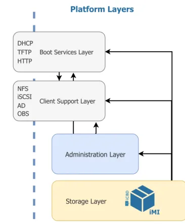
The iCBD platform encompasses the use of multiple services; to achieve a better under-standing of its inner workings, we can group these services in four major architectural blocks, as seen in Figure 3.1.
iCBD Machine Image (iMI) embodies the required files to run a iCBD platform client; this nomenclature was borrowed and adapted from Amazon Web Services’ AMI [5]. An iMI includes a VM template (with an operating system, configurations and applications), the iCBD boot package (a collection of files needed for the network boot and tailored to the operating system) and an assortment of configurations for services like PXE and iSCSI.
Boot Services Layer responsible for providing the initial code that supports network boot of client machines, the transfer a bespoke follow-up package (OS, ramdrive, initial scripts), using services such as PXE, DHCP, TFTP and HTTP.
3 . 2 . T H E A R C H I T E C T U R E Client Side Platform Layers Administration Layer Storage Layer iMI Boot Services Layer DHCP TFTP HTTP Client Support Layer NFS iSCSI AD OBS
Figure 3.1: iCBD Layers View
Client Support Layer provides support for client-side operations including, e.g., authen-tication, read/write storage space for client instances (since iMIs run on ‘diskless” workstations) and access to the users’ home directories.
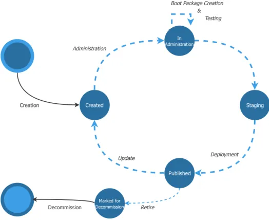
Administration Layer maintains platform users and the full iMI life cycle, from creation to retirement. Currently, administration is based on a custom set of scripts.
Storage Layer maintains the repository of iMIs and provides essential operations such as version control of the VM image files. Our work is fundamentally focused on this layer, extending it in such a way that a single repository abstraction can be built on top of the local/individual repositories through replication and caching. These local repositories are implemented on Btrfs or Ceph and may be exported to clients using NFS, iSCSI, REST and other suitable protocols.
In the next subsections, we will provide a more detailed description of each of the above-mentioned layers.
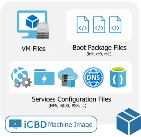
3.2.1 iCBD Machine Image
In its essence, an iCBD Machine Image is an aggregation of everything that is needed to run an Operating System within the iCBD platform – kernel, binaries, data and configu-ration files. For the sake of simplicity, we categorise iMI files into three main groups:
VM Files
Services Configuration Files
(NFS, iSCSI, PXE, ...)Boot Package Files
(init, rc0, rc1)Machine Image
Figure 3.2: iCBD Machine Image Files
VM Template files The main component of this group is the virtual machine template in the form of a read-only image. As described in Section 2.1.3, the anatomy of a template follows the standard VMware and KVM formats either with multiple files (i.e., Virtual Disk Files like.vmdk or .qcow) or a raw storage format (a disk image). iCBD Boot Package files In a network boot environment, such as the one used, there is
a need to keep a set of files that manage the boot process of the user’s workstation; these files can be included in the initialramdisk or transferred over HTTP later on,
when needed. Included in the boot package are: aBusyBox tool, an init file, and
at least two Run Control Script files (rc0 and rc1) that are responsible for starting network services, mount all file systems, and ultimately bring the system up into the single-user level. WithBusyBox (a single executable file with a stripped-down
set of tools), a basicshell is available during the boot process to fulfil all the required
steps.
Service Configuration files The iCBD platform uses several services, and some do re-quire particular settings in the configuration files. As an example, the ‘NFS exports” configuration file should reflect which file systems are exported, which networks a remote host can use, as well as a myriad of options that NFS allows; the same happens to iSCSI, where an iSCSI target needs to refer to a backing store for the storage resource where the image resides.
![Figure 2.2: An exemple of a Virtual Desktop Infrastructure, adapted from AppDS [9]](https://thumb-eu.123doks.com/thumbv2/123dok_br/15700998.1067199/33.892.171.715.171.458/figure-exemple-virtual-desktop-infrastructure-adapted-appds.webp)
![Figure 2.3: Conceptual overview of DaaS architecture, adapted from Intel [30]](https://thumb-eu.123doks.com/thumbv2/123dok_br/15700998.1067199/36.892.128.761.243.530/figure-conceptual-overview-daas-architecture-adapted-intel.webp)