The SmartVision Navigation Prototype for the Blind
J.M.H. du Buf
1, J. Barroso
2,3, J.M.F. Rodrigues
1,H. Paredes
2,3,
M. Farrajota
1,
H. Fernandes
3, J. José
1, V. Teixiera
3, M. Saleiro
11 Vision Laboratory – Inst. for Systems and Robotics (ISR), University of the Algarve (FCT/ISE), Faro, Portugal 2
GECAD, Knowledge Eng. and Decision Support Research Group, Inst. of Engineering of Porto, Porto, Portugal
3 University of Trás-os-Montes and Alto Douro, Vila Real, Portugal {dubuf, jrodrig}@ualg.pt and {jbarroso, hugof}@utad.pt
Abstract1— The goal of the project "SmartVision: active
vision for the blind" is to develop a small and portable but intelligent and reliable system for assisting the blind and visually impaired while navigating autonomously, both outdoor and indoor. In this paper we present an overview of the prototype, design issues, and its different modules which integrate a GIS with GPS, Wi-Fi, RFID tags and computer vision. The prototype addresses global navigation by following known landmarks, local navigation with path tracking and obstacle avoidance, and object recognition. The system does not replace the white cane, but extends it beyond its reach. The user-friendly interface consists of a 4-button hand-held box, a vibration actuator in the handle of the cane, and speech synthesis. A future version may also employ active RFID tags for marking navigation landmarks, and speech recognition may complement speech synthesis.
I.INTRODUCTION
Similar to the Greek project SmartEyes [9], the goal of the Portuguese SmartVision project is to develop and integrate technology into a portable device for aiding blind persons and those with severe visual impairments, about 180 million of which 40-50 mil-lion are completely blind. This device must be rela-tively small and cheap, and easy to assemble using off-the-shelf components. It must be extremely easy to carry and use, yet providing help during navigation and locating objects. It should be stressed that the device cannot replace the white cane; it will be an extension of the cane, issuing warning signals when approaching a possible obstacle or when the footpath in front is curved and the heading direction should be adapted. The device will not employ headphones as these block surround sounds. We assume that the user has adapted to the cane and relies on hearing. In this sense the device will be "non-invasive" such that nor-mal surround sounds and the device's signals, includ-ing verbal communications with queries and answers, are integrated in a natural way.
Acknowledgements: This research was supported by the
Portu-guese Foundation for Science and Technology (FCT), through the pluri-annual funding of the Institute for Systems and Robotics (ISR-Lisbon/IST), by the POS_Conhecimento Program which includes FEDER funds, and by the FCT project SmartVision: active vision for the blind (PTDC/EIA/73633/2006).
Sighted persons may have some difficulty in imagin-ing the problems which blind persons must deal with almost all of the time, because they take the extremely comfortable efficiency of the visual system for granted. One brief glance suffices to determine the heading direction to a specific goal, to cross a street and to spot possible obstacles, both static ones like loose or missing cobblestones and steps in the pave-ment, also moving ones like persons and dogs. In a pantry, there is no problem distinguishing between cans of tomatoes and baked beans, even if both have the same size and both are red. Hence, the ultimate goal of the project is to substitute a significant part of the visual system, which is very ambitious.
Even the development of a device which mimics a guide-dog (Am.: seeing-eye dog) is a challenge. Such dogs have been trained to guide their owner around all obstacles and to recognise landmarks like certain shops, going from landmark to landmark, with subtle commands and hints resulting from extensive training. However, even a guide-dog is of little help when its owner needs to go to a location which the dog does not know: its function is reduced to local navigation, negotiating obstacles, footpaths and zebra crossings, that is, if the owner is already familiar with that loca-tion. If not, both are lost and the owner must ask pass-ers-by, if there are any. An equivalent of a normal, printed map is required in order to not always have to rely on help by others and improve the autonomy of the user, with or without a dog.
From the above it is clear that we can distinguish three broad but linked applications: (1) local naviga-tion for centering on footpaths etc. and obstacle avoid-ance, in the immediate surrounding but beyond the reach of the white cane; (2) global navigation for finding one's way in the centre of the city, in a quarter, or in a shopping centre; and (3) object recognition, not only cans etc. on shelves in a pantry or supermarket, but also outdoor: bus stops, taxi stands, cash machines (ATM) and telephone booths. Also banks, post offices and shops, simply all objects which have a distinct function but which can serve as a landmark for global navigation. Such objects could be recognised by their physical structure (image), by their specific sign, or by some sort of mark like an RFID tag specifically em-ployed for blind persons.
Below we discuss technological solutions in general (Section 2) and the ones being developed in the pro-ject: the prototype (S. 3), GIS and the navigation module (S. 4), the vision module (S. 5), the white cane with passive RFID tags (S. 6) and the interface mod-ule (S. 7). We conclude with a discussion in Section 8.
II.TECHNOLOGIES AND INFRASTRUCTURES Technology can provide solutions to the three broadly-defined applications, even with off-the-shelf hard- and software, but computing power may be a limiting factor in portable and therefore small devices. Another problem is the necessary infrastructure to use the technology, like outdoor GPS and indoor Wi-Fi reception in combination with a GIS, the level of de-tail of the latter, plus extra infrastructure specifically devoted to blind persons. For example, many railway stations have bands of rippled pavement at the plat-forms. Such bands can be employed at many other locations to mark the centres of footpaths. If too ex-pensive, are there cheaper solutions? Since most roads are marked by white stripes which reflect light, it is also possible to mark footpaths, for example by re-flecting circles a few metres apart (see Fig. 4). During the day these can be easily detected by a miniature camera, but during the night a small light source is necessary, for example a powerful LED, carried by the user, which flashes every two or three seconds.
A large metro and railway station in Lisbon is equipped with loudspeakers which emit sounds of birds, with different sounds in different areas for global navigation, and most sighted passengers do not even notice the sounds. Spoken messages stored in electronic tags are provided by the “Talking Points” system [13] and the tags can be fixed to anything, from an entry of a building to its elevators, also to bus stops and busses. The latter system is a commercial one, the company only providing “turnkey” solutions.
There are many possibilities, but the main question is: how much is a civilised society willing to invest in infrastructure for relatively few users, knowing that the infrastructure will make a tremendous difference for those users. For example, the reflecting circles mentioned above could be substituted by a solar-power driven LED in a small armature with a white-glass cover in the pavement, such that blind persons do not need to carry a light source when it is dark. One armature including a small solar panel, day-night sensor and other electronics might cost a few euro if mass produced. Electronic parts are so cheap that LEDs in special armatures can flash like a temporal barcode, too fast to be noticed by sighted persons, with codes linked to special places like footpath bifur-cations and entries of buildings. However, it costs more to drill the holes and mount the armatures, unless the infrastructure is planned in new
develop-ments. Also, such armatures provide a solution when it is dark, but what during a sunny day when the tem-poral barcode cannot be detected?
An equivalent solution is to use RFID tags: passive tags without battery, which are cheap but have a small action radius, and active tags with battery or external (solar) power supply, which are more expensive but have a large action radius. To be useful, passive tags must be drilled into the pavement at rather small dis-tances if the tip of the cane is equipped with a small sensor and the swaying cane should encounter the tags with a reasonable probability (see Section 6). Active tags, on the other hand, are more suitable for marking important landmarks like entries of buildings and shops, with a distance of 5 to 10 metres. Since both passive and active RFID tags emit unique codes, the codes can be stored in a database. Passive tags can be used for local navigation at footpath crossings etc., whereas active ones are better for global navigation, both in- and outdoor: the name of a landmark like a shop in the GIS for position calibration if GPS or Wi-Fi reception is not available. See also Section 3.
Concerning object recognition in a supermarket or household pantry, if the blind person is wearing a camera at chest height, perhaps three shelves can be analysed with sufficient optical resolution. But in a supermarket these shelves normally carry the most expensive products, whereas the cheapest ones are on the bottom shelves. In addition, all shelves are cramped with products, because shelf space is money, hence products are not well separated and this ham-pers object segregation and identification (see Section 5). In a pantry, this problem can be avoided and both top and bottom shelves can be reserved for bigger things which can be easily identified by hand. In any case, it should be possible that a blind person takes an object in his hand, holds it at arm length in front of the camera attached at chest height, and uses a special command to ask the system to identify the object.
An alternative is to label objects with a QR barcode, a square one which can hold more information [8]. A mobile phone with a camera and QR barcode software sends the code to a URL server and receives an audio file, created by text-to-speech, with a description. Of course, this solution can be applied anywhere, soft-ware for printing and reading QR barcode labels is freely available, the price is almost nil apart from server and database maintenance, but the labels must always be visible. Instead of putting the labels on the products it is possible to put them on the shelves, provided they are checked on a regular basis and no one puts products at wrong locations. A complication when using a camera at chest height is the long dis-tance between camera and barcode label, which also implies that there may be many labels in the camera's field of view. If a portable computer is used instead of
a mobile phone, all software can be integrated and no wireless communications are required (text-to-speech may be required anyway; see Section 7).
For localising few but very important objects, like a bunch of keys at home or a suitcase on a conveyor belt at the luggage claim area of an airport, there already exist good solutions: an electronic label which can be attached to the object and a small hand-held gadget with a push button. The label beeps and it works with ultrasound or radio signal. It is rather easy to make a gadget with a few buttons for localising various ob-jects. Here we can assume that blind persons do not put very important objects nor such a gadget at arbi-trary locations, but: errare humanum est!
There are other technologies which can be em-ployed, notably ultrasound detectors for spotting pos-sible obstacles at foot- or head-height [19]. A recent development is Nokia's indoor positioning technology [3] based on DoA (direction-of-arrival), with an accu-racy of 2-5 m. Another technology employs ToA/AoA (time/angle of arrival) with UWB (ultra-wideband), aiming at 10 cm. Pending availability of such ad-vanced technology, one must select what is currently available and integrate this into a working system which is modular, such that future developments can be easily and rapidly adopted. Below we describe the components of the SmartVision system.
III.PROTOTYPE OVERVIEW
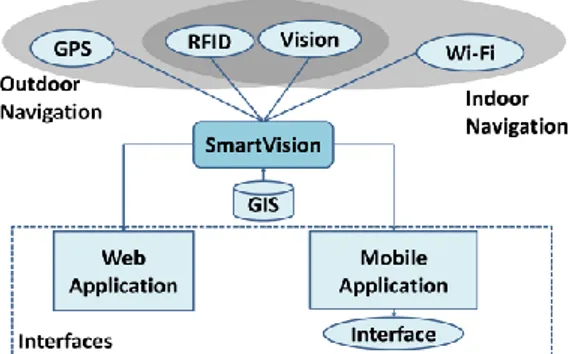
The system integrates GPS (in the future the Euro-pean Galileo equivalent) and Wi-Fi with a GIS. GPS is for outdoor navigation and Wi-Fi mainly for indoor, specifically in bigger buildings like a shopping centre or a university's administration. However, Wi-Fi ac-cess points are still not ubiquitous and GPS may not be available in narrow streets and in bad weather. Therefore, a fail-safe solution is required such that the user can still be assisted: by active RFID tags with calibrated positions, and if these cannot be located by visual object recognition, and, if all else fails, by the user asking a passer-by to bring him to the nearest landmark which is included in the GIS. The basic idea is that the user's system always has a global map with enough detail along the planned route. The actual position is constantly calibrated using GPS, Wi-Fi or RFID tags, whatever is locally available, and each time Wi-Fi reception is possible and a significant distance has been traversed, the local map is updated by the GIS server, for example in a radius of a few kilometres. This way the user can always consult the GIS for taking the best or shortest path to a destiny and for knowing the major landmarks along the route. The system consists of a few modules; see Fig. 1. The central SmartVision module is responsible for managing all other modules and the communications with these. This module also receives input from the
user (not shown) and takes decisions about what in-formation the user should get from the system. Also not shown are the speech and other interfaces (see Section 7), nor is the electronic compass which will be integrated in the future.
Figure 1. SmartVision prototype structure. The GIS and navigation modules provide regular updates of the user's current geographic coordinates to the SmartVision module, either using GPS in outdoor or Wi-Fi in indoor environments. Both GPS and Wi-Fi are complemented by RFID and computer vision, and if GPS or Wi-Fi signals cannot be received the SmartVision module must rely on RFID and computer vision. The latter are common to both in- and outdoor environments and serve to detect specific landmarks. Each location technology has a specific accuracy and the navigation modules always choose the best accu-racy from the ones which are available at any moment.
Concerning hardware, one small RFID reader is placed in the white cane for detecting passive tags in the pavement, see Fig. 6, and the camera is chest-mounted. The GPS unit is connected by Bluetooth and Wi-Fi is a built-in component of the portable com-puter. In the future, a second RFID reader will be connected to the computer in order to detect active tags attached to landmarks.
The navigation modules are responsible for route planning and for providing information about sur-rounding points-of-interest (POIs). They connect to the SmartVision module and request GIS data and location data. To get the GIS data, the SmartVision module queries the GIS server in order to get a local map and its POIs. The user's position is obtained from the location modules. After analysing the requested data, the navigation modules feed the SmartVision module with navigation instructions. The amount and accuracy of the GIS data stored on the GIS server is critical in order to provide the best instructions.
The vision module provides local orientation in-structions by detecting sidewalk borders and possible obstacles in front on the path, for guiding the user safely. It also detects already known landmarks (GIS in the immediate surrounding) in order to confirm encountered POIs and re-calibrate the user's position if
GPS or Wi-Fi cannot be received. In addition, this module can be used to detect and recognise objects on demand. The camera used is the Bumblebee2 from Point Grey Research Inc. Being a stereo camera, it is possible to extract disparity information. This infor-mation is calibrated in order to estimate the distance between the user and a detected landmark (in the fu-ture to be combined with heading information from an electronic compass attached to the camera unit).
Finally, the interface module is the link between the SmartVision module and the user. At the moment it serves two outputs and one input. The two outputs are text-to-speech audio and vibration actuators. The vibration actuators are used for local navigation, i.e., obstacle avoidance and heading direction. The audio interface is used for navigating the menus and provid-ing POI information. The user provides input by usprovid-ing a small four-button device to navigate a simple menu system and to select options.
IV.GIS AND NAVIGATION MODULES
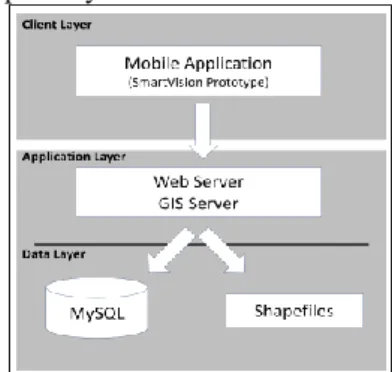
Given the fact that Wi-Fi is not everywhere avail-able, all or most information required for global navi-gation must be stored on the SmartVision prototype. This way it is possible to have access to the informa-tion whatever the scenario, both in- and outdoor, without a need to regularly query the GIS server. The geographic information stored on the prototype is updated when Internet connection is available, through the use of webservices. The information is stored in digital map files, or shapefiles [7], and a MySQL database which holds landmark details. For the distri-bution of geographic information, the adopted archi-tecture is three-tier client/server [22]. In this model, the client application, i.e., the SmartVision prototype, handles and provides geographic information to the user. For a detailed description see [7, 10]. Figure 2 illustrates the client/server architecture.
The navigation modules handle aspects related to the computation of the route that the user must follow, from the initial or actual position to the chosen des-tiny. In terms of functionality, all local POIs in the database are transmitted to the user by the interface module, in order to choose a desired one. Then, navi-gation instructions are issued using Dijkstra's Shortest Path First (SPF) routing algorithm. According to Ertl [4], this algorithm is able to calculate, in a graph, the shortest path from a starting vertex to a destination vertex, and this algorithm provides a balanced solution between calculus efficiency and implementation sim-plicity. Obviously, the road layer in the map is built in a manner similar to a graph, i.e., the points where a road begins, is intersected and ends correspond to the graph's vertices and these are linked by the graph's edges. See [7, 10] for further details.
Concerning the use of Wi-Fi, this technology is also used to compensate for the lack of GPS reception inside buildings. By using the calibrated locations of Wi-Fi access points (APs) in the GIS in combination with a triangulation method based on the APs’ signal strengths, it is possible to approximate the user's posi-tion with an error margin of 7-8 m, which is worse than Nokia´s margin of 2-5 m [3]. Implicitly we as-sume that there are at least three APs within reception range, i.e., at the time the localisation by Wi-Fi is requested. This solution provides an indoor localisa-tion system very similar to outdoor GPS. However, if less than three APs are within reception range, an alternative to re-calibrate the user's actual position is required. Therefore, in the near future tests with active RFID tags will be conducted in combination with visual landmark (object) recognition by the Vision module. These extensions are required in any case, i.e., if no or few APs are present inside a building or GPS is temporarily not available outdoor.
Figure 2. Three-tier client/server architecture. V.VISION MODULE
The Vision module provides information for local navigation: the heading direction to keep the user within safe boundaries in corridors and paths includ-ing footpaths (sidewalks), possible obstacles in front and beyond the reach of the white cane, and known objects which may serve as navigation landmarks or which can be a destiny (bus stop, taxi stand, cash machine, post office, etc.). The latter aspect must still be studied by using real test video sequences, although first results on the recognition of household items are available (Fig. 5). This module consists of comple-mentary sub-modules: (A) sidewalk and path detec-tion; (B) obstacle detecdetec-tion; (C) landmark detecdetec-tion; (D) detection of moving persons or other objects pos-sibly on collision course; and (E) object recognition. A. Sidewalk and path detection
There exist a few methods to detect the borders of sidewalks [18]. We detect them by using Canny´s edge detector in combination with a tracking mask to obtain straight lines, from the bottom of each frame to the top, characterised by slope, length and proximity to the left and right boundaries of the frame. The
de-tected borders define the horizontal position and width of an obstacle detection window (ODW). As its name indicates, the latter is used for obstacle detection. For a detailed description see [2]. Although first results were good, a new approach is being explored: borders are detected using an adaptive Hough-transform space, which is faster and yields more robust results [12]; see Fig. 4 (bottom).
B. Obstacle detection
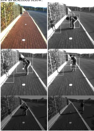
Two different methods are applied within the ODW. The first one counts variations of gray values, i.e., local maxima and minima, on each horizontal line inside the ODW. Then, outliers are reduced by averag-ing counted variations over groups of lines, and varia-tions over these groups are combined into a single value which indicates whether the frame has a possi-ble obstacle or not. Final confirmation is obtained by combining the results of a few subsequent frames. The second method is based on irregularities in vertical and horizontal histograms of the binary edge image. An obstacle can lead to two different signatures: if the pavement is smooth, an obstacle may appear as a local excess of edge points, but if it has a strong texture there will be a huge amount of edge points and an obstacle may appear as a local deficiency (lack or gap) of edge points. The second method is used to confirm the result of the first one, but it also serves to detect the size and position of an obstacle in order to guide the user away from it. Figure 3 shows successive frames 1 to 14 of a test sequence with their annotation, i.e., image type and obstacle alert.
Figure 3. An annotated test sequence with the ODW and a detected obstacle.
C. Landmark detection
By using a stereo camera, disparity information can be extracted from the captured image frames. Cali-brated disparity yields a distance map, for example for
knowing the distance between the user and special navigation landmarks on the pavement or, when such landmarks are not present, for detecting the correct heading direction in front but also vertical obstacles like trees, light poles and traffic signs.
First experiments were conducted with high-contrast circles (Fig. 4, top-left) which can easily be segmented by thresholding, followed by edge detection and the Hough transform for circles. Combining the left and right frames, the distance can be computed and also the orientation for advising the blind user to maintain or correct his heading direction [6]. The more general solution, not based on high-contrast circles on the pavement, is already being pursued: general image disparity but, because of limited CPU power available on the portable device, restricted to matching left-right images only at the height of the obstacle detection window. This solution is closely related to optical flow as described below.
Figure 4. left: input frame with markers. Top-right and middle: a moving person is picking up one
marker and has been detected, also the person's shadow (white rectangles). Bottom: detected sidewalk
borders with and without partial occlusion. D. Detection of moving objects
Keypoints are 2D singularities like edge crossings and line ends [17]. Keypoint annotation (edge types, orientations, etc.) in combination with multi-scale processing facilitates various processes such as image matching (stereo and optical flow) and object segrega-tion and tracking. Here we focus on optical flow in
order to detect moving objects in front of the user, both approaching objects and those which cross the user's path.
Instead of working with mere point (keypoint) clouds in combination with mathematical matching methods, there is a growing interest in using addi-tional information [20]. There are four reasons for doing this: (1) By definition, keypoints at any scale are caused by junctions of lines and edges at the same scale, and this line/edge information is tractable for keypoint annotation. (2) At coarser scales the bigger filter kernels will lead to few detected lines, edges and keypoints, and the same effect will occur in image pairs - stereo for disparity; sequential for optical flow. (3) Going from a coarse scale to the finest one, few keypoints are located at the centre of an object, then more keypoints are found at object parts, and finally many keypoints at object (and contour) details. (4) Matching annotated keypoints is much easier than matching mere point clouds, especially when one starts at a coarse scale and the matching results there are used to steer the matching process at a finer scale, the procedure being repeated until the finest scale.
The solution of the correspondence problem based on annotated keypoints combines left-right (stereo) and successive (optical flow) frames, comparing key-points in an area with a radius proportional to the filter kernel's size, and starting at coarse and going to fine scale. At each scale the corresponding vectors are computed or refined. In object segregation and object tracking the processing is the same, matching key-points being linked over and within scales by using a multi-scale tree structure [20]. With this information we can track the movements of persons, animals or other obstacles (Fig. 4 top and middle row); for more details see [12]. In the future, the goal is to detect which object is moving - man, animal or other - and the type of movement - laterally crossing or approach-ing. It should be stressed that the goal is not general scene analysis; the processing is only applied between the detected path borders and at short range.
E. Object recognition
An important goal is to locate household items, for example on shelves in a pantry, like toothpaste or a bottle of ketchup. To this purpose we use the well-known algorithm coined SURF (Speeded Up Robust Features), which is a scale- and rotation-invariant interest-point detector and descriptor [5]. Bay et al. [5] claim that it outperforms previously proposed schemes like SIFT with respect to repeatability, distinctiveness and robustness, and that it is faster. All this is achieved by relying on integral images for image convolutions and on the strengths of the best existing detectors and descriptors - Hessian matrix-based
de-tector and distribution-based descriptor - simplifying these methods to the essential.
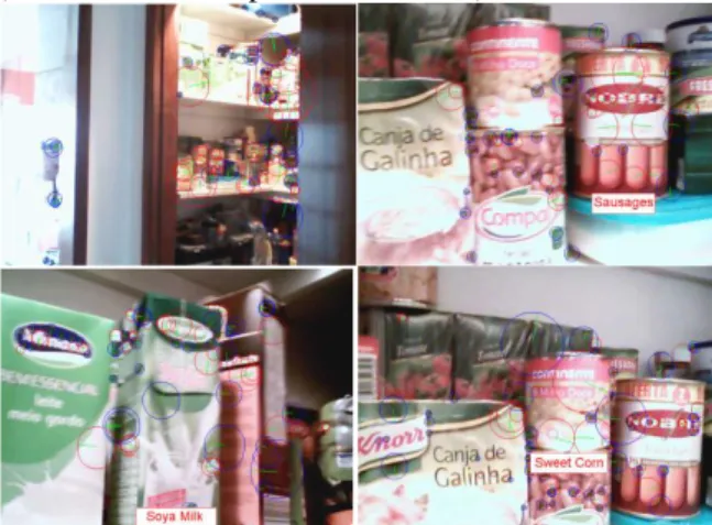
Extensive tests are being conducted with many typi-cal household objects, using the OpenSURF library [1], a C/C++ implementation. Depending on the com-plexity of each object, a single or a few different views are used for training, their features being used in realtime for locating and identifying the objects arranged on shelves. Figure 5 shows typical images with recognised objects. As expected, the recognition rate is very good, provided that the camera is at rea-sonably short distance, about 0.5 m. Of course, the user must be trained in holding and pointing the cam-era, also in communicating with the system in order to optimise performance. In the near future, similar tests will be conducted to recognise bigger but important objects for navigation, first indoor (elevator, toilet, welcome desk, furniture, plants) and then outdoor (cash machine, telephone booth, etc.).
Figure 5. Typical views of household items on shelves which have been located and recognised using
the OpenSURF software.
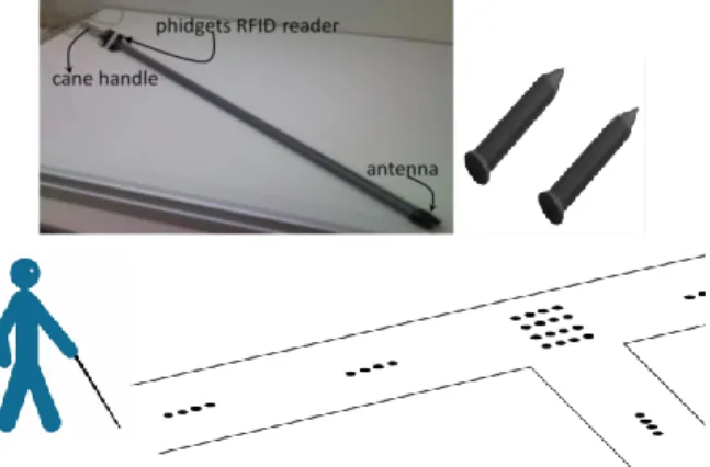
VI.WHITE CANE AND PASSIVE RFIDTAGS Above, the use of white markers on the pavement for aiding local navigation was discussed. One of the main problems of such markers is the necessity of a light source when it is dark. An alternative solution is to use passive RFID tags in the pavement, which al-ways respond provided that a signal-emitting antenna is at close range, less than 10 cm. Experiments were conducted with an RFID antenna in the very tip of a cane made of light PVC, similar to the ones used by blind persons. The handle contains a vibration actuator and close to the handle was mounted the tag reader with Bluetooth interface; see Fig. 6 (top-left) and [11]. The RFID tag reader used is from Phidgets, mainly because of previous experience and easy implementa-tion. The passive tags have a working frequency of 135 kHz. The tags have the shape of a nail or golf tee, 2.5 cm long and 4 mm wide, and the electronics are fixed inside a hard and resistant plastic encapsulation;
see Fig. 4 (top-right). The tags can be easily inserted into drilled holes in the pavement.
In the experiments we tested different tag layouts, both in a laboratory and on UTAD Campus, in order to find the best layout. The main problem is the com-bination of the walking speed of the user, the swaying of the cane and the distance of the cane's tip to the surface of the pavement, i.e., the probability of “hit-ting” a tag with some regularity. Initially the tags were distributed on the pathway along three parallel lines: two lines close to the path borders and one line in the centre to alert the user to special events like fixed obstacles (trash cans, trees) and change of direction. To this end the codes of the tags are stored in a small database together with event types, and the cane's vibrator is activated with different temporal patterns. In a second configuration, a single line along the path's centre was tested in combination with four-by-four tag arrays at bifurcations etc.; see Fig. 6 (bottom). The latter solution proved to be better, only requiring additional tests in order to optimise the tags' spacing for increasing the “hit” rate. Results of the tests and further details are described in [11].
Figure 6. Top-left: PVC cane with RFID reader. Top-right: golf tee-shaped passive RFID tags. Bottom:
proposed layout of the tags in the pavement. VII.INTERFACE MODULE
When developing a navigation aid for visually im-paired users, the user interface has to be intuitive and extremely easy to use [21]. The interface can only rely on touch and hearing, but it may not interfere with normal hearing of surround sounds nor the normal use of the white cane. The actual version of the SmartVi-sion prototype employs speech synthesis, a vibration actuator in the handle of the cane, and a small hand-held box with only 4 pushbuttons. Each interface has a specific use. The speech module is used to guide the user with brief messages, or longer messages but only when intentionally requested by the user. The vibra-tion module is used when very simple instrucvibra-tions like “turn left” or “turn right” are issued. One study pro-posed that vibration actuators could be used in the
shoes [14], but this might interfere with the normal “feeling” of the type of pavement if more complex stimulation patterns are being used, or it may distract the user. Extensive experiments are required to find optimal solutions, taking into account that the users need sufficient time to adapt to the different solutions. At the moment the pushbutton box is the only input device to the prototype. Linked to the computer by a simple USB interface, different combinations of the four buttons allow the user to request information and to navigate through a simple menu system [7]. For instance, the user is able to ask for detailed informa-tion about the surrounding environment, or only one specific landmark. If available, this information will be provided by the speech module. The speech mod-ule consists of a Dynamic-Link Library (DLL) which uses the Microsoft speech synthesizer API. This DLL also allows to select the voice and output device, and to control volume and pitch. In spite of providing all necessary or available information for guidance, the audio interface is limited to speech synthesis. In prin-ciple, speech recognition can also be employed, but may be less reliable near roads with heavy traffic or at sites with loud music or many talking people.
VIII. DISCUSSION
In this paper we described the current version of the SmartVision prototype, which integrates a GIS with positioning by GPS and Wi-Fi, also computer vision for path and obstacle detection. In the near future, active RFID tags will be integrated for landmark de-tection if GPS and Wi-Fi reception are not possible, as will be an electronic compass in order to know the heading direction of the user, possibly also to give instruction to correct the heading direction.
The GIS of UTAD campus [7] has been prepared, but it will be refined and extended by a few indoor locations to test also navigation in big buildings. The visual functions will be extended by stereo vision in order to estimate distances to objects and obstacles, and visual recognition of important landmarks, which extends recognition of household items, is already being explored.
The algorithm for optical flow is based on a biologi-cally motivated model of processing in the human visual system, which also entails focus-of-attention, object segregation, categorisation and recognition, also stereo disparity. Although most of those models are very promising [16, 17], their application in real-time on a portable computer may not be possible be-cause of limited CPU power. For this reason simpli-fied algorithms must be applied at a reasonable frame rate. However, CPU power of portable computers is rapidly increasing.
The FCT-funded project SmartVision will terminate mid-2011, but a follow-up project of two years has
already been approved. This extension suffices to optimise all modules and to include the newest and best localisation solutions like Nokia's indoor with a better precision. In addition, extensive field tests are planned in collaboration with ACAPO, the Portuguese association for amblyopes and the blind. The goal is to convert the prototype into a real system which can be assembled and maintained by non-experts, with de-tailed instructions. This system is coined Blavigator, from blind navigator.
REFERENCES
[1] C. Evans. “Notes on the opensurf library”, Univ. of Bristol, 2009. www.chrisevansdev.com/ computer-vision-opensurf.html
[2] D. Castells, J.M.F. Rodrigues, J.M.H. du Buf. “Obstacle detection and avoidance on sidewalks”. Proc. Int. Conf. on Computer Vision - Theory and Applications (VISAPP2010), Angers, France, 17-21 May, 2010, Vol. 2, pp. 235-240.
[3] F. Belloni, V. Ranki, A. Kainulainen, A. Richter. “Angle-based indoor positioning system for open indoor environments”. Proc. 6th Worksh. on Posi-tioning, Navigation and Communications, Buda-pest, April 5-8, 2009, pp. 261-265.
[4] G. Ertl. “Shortest path calculation in large road networks”. OR Spektrum, Vol. 20, pp. 15-20, 1998.
[5] H. Bay, T. Tuytelaars, L. Van Gool. “Surf: Speeded up robust features”. Proc. Europ. Conf. on Computer Vision, 2006, Vol. 1, pp. 404-417. [6] H. Fernandes, P. Costa, V. Filipe, L.
Hadjuleontia-dis, J. Barroso. “Stereo vision in blind navigation assistance”. Accepted for World Automation Congress, Kobe, Japan, Sept. 19-23, 2010. [7] H. Fernandes, T. Adão, N. Conceição, H. Paredes,
P. Araújo, J. Barroso. “Using GIS platforms to support accessibility: the case of GIS UTAD”. Proc. Int. Conf. on Universal Technologies, Oslo, Norway, May 19-20, 2010.
[8] H.S. Al-Khalifa. “ Utilizing QR code and mobile phones for blinds and visually impaired people”. Proc. 11th Int. Conf. on Computers Helping Peo-ple with Special Needs, Linz, Austria, 2008, Springer LNCS 5105, pp. 1065-1069.
[9] I.K. Kitsas, K.J. Panoulas, V.E. Kosmidou, S.A. Taplidou, C.D. Saragiotis, L.J. Hadjileontiadis, S.M. Panas. “SmartEyes: An efficient mobile phone/navigator for blind or visually impaired people”. Proc. Forum for the ICT Professionals Congress (FITCE 2006), Athens, Greece, Aug.-Sept., 2006.
[10] J. Almeida, H. Fernandes, V. Filipe, J. Barroso. “Web platform architecture to support the geo-graphic information system of the University of Trás-os-Montes and Alto Douro Campus”. Proc.
Int. Conf. on New Trends in Information and Ser-vice Science, Beijing, China, June 30 – July 2, 2009, pp. 1112-1117.
[11] J. Faria, S. Lopes, H. Fernandes, P. Martins, J. Barroso. “Electronic white cane for blind people navigation assistance”. Accept. for World Auto-mation Congress, Kobe, Japan, Sept. 19-23, 2010. [12] J. José, M. Farrajota, J.M.F. Rodrigues, J.M.H. du Buf. “A vision system for detecting paths and moving obstacles for the blind”. Int. Conf. on Software Development for Enhancing Accessi-bility and Fighting Info-exclusion, Oxford, UK, Nov. 25-26, 2010 (these proceedings).
[13] J. Stewart et al. “Accessible contextual informa-tion for urban orientainforma-tion”. Proc. 10th Int. Conf. on Ubiquitous Computing, Seoul, Korea, Sept. 21-24, 2008, pp. 332–335.
[14] J. Watanabe, H. Ando. “Pace-sync shoes: Intui-tive walking-pace guidance based on cyclic vibro-tactile stimulation for the foot”. Virtual Reality, Vol. 14:2, 2010.
[15] J.A. Martins, J.M.F. Rodrigues, J.M.H. du Buf. “Focus of attention and region segregation by low-level geometry”. Proc. Int. Conf. on Com-puter Vision-Theory and Applications, Lisbon, Portugal, Feb. 5-8, 2009, Vol. 2, pp. 267-272. [16] J.M.F. Rodrigues, J.M.H. du Buf. “Multi-scale
lines and edges in V1 and beyond: brightness, ob-ject categorization and recognition, and con-sciousness”. BioSystems, Vol. 95, pp. 206-226, 2009.
[17] J.M.F. Rodrigues, J.M.H. du Buf. “Multi-scale keypoints in V1 and beyond: object segregation, scale selection, saliency maps and face detection”, BioSystems, Vol.
86, pp. 75-90,
2006.[18] K. Kayama, I. Yairi, S. Igi. “Detection of side-walk border using camera on low-speed buggy”. Proc. IASTED Int. Conf. on Artificial Intelligence and Applications, Innsbruck, Austria, Feb. 13-15, 2007, pp. 262–267.
[19] L. Kim, S. Park, S. Lee, S. Ha. “An electronic traveler aid for the blind using multiple range sen-sors”. IEICE Electronics Express, 11(6):794–799, 2009.
[20] M. Farrajota, J.M.F. Rodrigues, J.M.H. du Buf, “Multi-scale keypoint annotation - a biological approach”. Proc. 15th Portuguese Conf. Pattern Recogn., Aveiro, Portugal, Oct. 23, 2009, 3 pp. [21] R. Kowalik, S. Kwasniewski. “Navigator - A
talking GPS receiver for the blind”. Springer LNCS 3118, 2004, pp. 446-449.
[22] Z. Peng and M. Hsiang. “Internet GIS: distributed geographic information services for the internet and wireless networks”. New Jersey: John Wiley & Sons, Inc, 2006.