ISSN 1549-3636
© 2010 Science Publications
Corresponding Author: Abbas M. Ali, Center for Artificial Intelligence Technology, University Kebangsaan Malaysia, Bangi, Selangor, Malaysia
Indoor Navigation to Support the Blind Person Using True
Pathway within the Map
Abbas M. Ali and Md Jan Nordin
Center for Artificial Intelligence Technology, University Kebagsaan Malaysia,
Bangi, Selangor, Malaysia
Abstract: Problem statement: Map creation remains a very active field in the robotics and AI community, however it contains some challenge points like data association and the high degree of accuracy of localization which are seems to be difficult in some cases, more than that, most of these study focus on the robot navigation, without any consideration for the semantic of the environment, to serve human like blind persons. Approach: This study introduced a monocular SLAM method, which uses the Scale Invariant Features Transform (SIFT) representation for the scene. The scene represented as clouds of sift features within the map; this hierarchical representation of space, serving to estimate the current direction in the environment within the current session. The system exploited the tracking of the same features of successive frames to calculate scalar weights for these features, to build a map of the environment indicating the camera movement, then by comparing the camera movement of the current moving with the true pathway within the same session the system can help and advice the blind person to navigate more confidently, through auditory information for the path way in the surroundings. Extended Kalman Filter (EKF) used to estimate the camera movement within the successive frames. Results: The experimental work tested using the proposed method with a hand-held camera walking in indoor environment. The results show a good estimation on the spatial locations of the camera within few milliseconds. Tracking of the true pathway in addition to semantic environment within the session can give a good support to the blind person for navigation. Conclusion: The study presented new semantic features model helping the blind person for navigation environment using these clouds of features, for long-term appearance-based localization of a cane with web camera vision as the external sensor.
Key words: SIFT, clouds of features, EKF, mono-SLAM
INTRODUCTION
Map creation remains a very active field in the robotics and AI community, especially in the domain of mobile robotics. Reliable sensor information and its comparison with a given model are crucial in order for self-localization and meaningful navigation.
Acquiring maps of the environment is a fundamental task for autonomous mobile robots, since the maps are required in different higher level tasks, such as navigation and localization. This map can be provided a priori, or can be built by the robot as it explores the environment. The situation in which an autonomous moving the mobile robot through an unknown space and building environment (map) while simultaneously using this map to compute its absolute location is called Simultaneous Localization and Mapping (SLAM). This problem has received
significant attention during the past decades. Path planning within this map is the process by which determining a feasible path to a goal. However this path some time is difficult to follow it, since the inaccurate movement of the robot. The process of finding some image within this path is very important and it is called localization. The localization is done by the system when tracking and finding the features in the current view then understanding these features. These features depend on techniques used like SIFT, Harris, SUSAN, SURF or others.
VISUAL MONO-SLAM, the second approach which uses two cameras at the same time for navigation called stereo VISUAL-SLAM as (Miro et al. 2006; Li and Perona, 2005). The two techniques depend on an important features extracted for localization. It includes some delay, comes from the initialization method, to recognize the initial landmark from the system, some system uses many images from different view point, for matching in the first stage and then determine the landmark and relevant information. The correct recognition of the scene is important, for this initialization, what can be seen as distinctive and discriminative should be taken. In this study a Mono-SLAM will formed from clouds of features it will be used for directions and movement within the session, for example the cloud of the TV will be in the east for example, while the cloud of windows and other objects will be in the north or west as fixed in the room, this will help the system to estimate the way while the blind person walking in the session and give more advices, due calculating the differences between the successive frames within the session. The pathway will be derived when the camera move and the objects inside the cloud shifted from the centre of the camera. In this study a MONO-SLAM using cloud of SIFT features approach will be described. The system navigates and localizes according to the clouds in the intended direction. It is an effort towards conceptualizing environment on the basis of the human compatible representation. Such a representation and the resulting conceptualization would be useful for enabling the blind person to be cognizant of their environment; while walking within the session.
Related works: Visual SLAM has received a lot of attention from the researchers to finish this challenge, several different approaches, have been tried with differing degrees of success. Currently, the SLAM has two contrasting problems to be solved, which are often faced with a trade-off:
• The map precision
• The computational requirement for real-time/real-world implementation
The original stochastic solution to the SLAM problem by (Smith et al., 1988) is now more than twenty years old. The main problems is that how to find the accurate position in unknown environment. The study in this field; can be divided into two groups, the first group is based upon image processing and recognition (David, 2004); the second group relies on
wireless networking and sensor technologies as in (Hub et al., 2004).
The underlying methods (sensor Vs sensor less) to solve the SLAM problem differ, in sensor information, algorithm used and the resulting maps dimensionality (2D or 3D) with their representation of the environment (for example point clouds or occupancy grids). (Davison et al., 2007) have developed real time monocular SLAM method with only one camera. They used Harris feature detector to locate the feature points within the scene, Then find the same feature point in the next frame, the image patch around the feature point taken and will be searched to find the new position for the feature point. In (Montiel et al., 2006), the inverse depth parameterization method used to represent 3D feature point with 3 degree of freedom (dof), instead of 6° of freedom to reduce the computation load. In (Chwan and Yung-Pyng, 2007) changed the Harris features to SIFT features to improve its robustness.
The one similarity between all these study is that all of them focus how to make a good navigation for the robot like human being navigation. However this is good for the blind person but in another side the context of the environment will not be known by the robot and there is some failure to encode the semantics of the environment for the blind person.
The contribution of this study is that making semantically environment representation for the blind person to navigate and recognize objects needed, from building map as a talker Visual SLAM helping the blind person to navigate more confidently in the environment with a cheap sensor like web camera.
MATERIALS AND METHODS
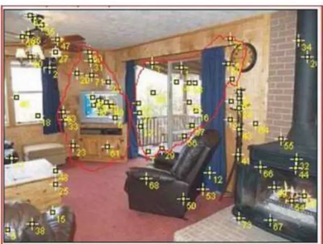
Clouds model: The correct recognition of the scene is important, for the initialization of the navigation within the session; some features are not distinctive in the level of object for example doors, or windows, so it is much better to discriminate them by adding features for near objects to it, the collection of features construct a cloud of features distinct from the other. Then the cloud features known from the all session it will give a good indication for the direction of the navigation. Figure 1 shows a session from repeated objects for the scene.
Fig. 1: Clouds of features
This model is also remains uses appearance based approach as in (Booij et al., 2005; 2007a; 2007b), by memorizing a set of images taken from the environment for only the known objects stored in a temporary database within the graph of the environment for navigation.
The temporary visual cloud as in (Abbas and Md, 2009) used by this model, is an intelligent technique to increase the speed of the system, for getting the right direction when navigation happen with more information and advices during navigation process, in addition to give intelligent dimension to the system.
SIFT feature detection: The blind person cannot be controlled for any direction as done in the robotics and also the camera cannot be focused in a specific view point. For that reason this model treats the scenes as a set of SIFT features. SIFT was developed by David (2004) Lowe (1999) for image feature generation in object recognition applications. The SIFT algorithm compromise four steps: Scale-space extreme detection, key point localization, orientation assignment and key point description.
These features are invariant to image translation, scaling and rotation and partially invariant to illumination changes.
In order to guide the blind person to their desired destination in a reliable and robust way, SIFT features (David, 2004) used in an image by locating the extreme of the Difference of the Gaussian convolute images (DoG) between two scales σ and k σ:
2 2 2 x y 1 2
1 G (x, y, ) e
2
+ −
σ σ =
πσ (1)
Fig. 2: Keypoint descriptor
L(x, y, ) G(x, y, ) I (x, y)σ = σ ∗ (2)
D(x, y, ) (G(x, y, k ) G(x, y, )) I (x, y) L(x, y, k ) L (x, y, )
σ = σ − σ ∗
= σ − σ (3)
Among the 26 surrounding points in the image scale space. The image scale space is formed the image plane with the scale value σ of the convoluting Gaussian function as the third coordinate axis. By searching for extreme of the DoG in the image-scale space, the SIFT method achieves the scale-invariant property. In other words, a surface texture detected by SIFT at different relative distances (with different scales) will be identified as the same feature point (Chwan and Yung-Pyng, 2007). The feature points will be detailed fit to: sub-pixel and sub-scale location scale determination and Ratio of principal curvature to reject edges and flats (detect corners), to further improve the accuracy of the extreme location in the scale space to the subpixle level, each key point will assigned to an orientation based on local image gradient direction. To generate the key point description, the algorithm uses a 4×4 subspace, each represented by the gradients in 8 orientations. Each feature is therefore, described using a 4×4×8 = 128 byte vector as in Fig. 2, as in the previous study (Abbas and Md, 2009). The cloud of SIFT can be expressed as:
C(I) = {f(O1), f(O2),….f(On)}
where, f(Oi) can be represented as a set of sift features f(Oi) = sift(Oi) = {fOi1,fOi2,…..fOin}.
The system calculates the weight for the visual cloud, where concentrated in the scene image. According to the weight the system will recognize, localize and advice the blind person within the graph.
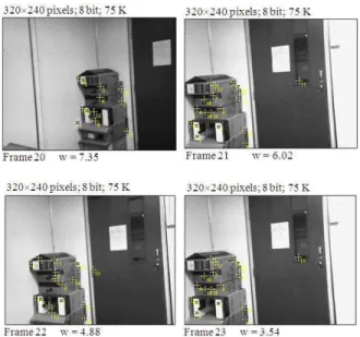
Fig. 3: Sequence of frames and weights
Figure 3 also shows the movement of the hand held camera from one place to another. One can observe that the weight decreased for the cloud of package when the door comes to the center of the view. This information is also useful to determine the state of the blind person and then feed to Kalman filter to estimate the next state for the navigation in the session. To make this study compatible with the previous research (Abbas and Md, 2009), the localization for the blind person can be performed effectively using visual clouds, for traversing the nodes in the workspace. The workspace environment representation as a weighted graph G = (V, E), will help to divide the database into groups of images as a node. The nodes will in turn divided into clouds of features for the scene inside the node. A graph of n nodes contains m clouds for each node. Edges join pairs of nodes between which the straight line path between the corresponding clouds. The process of localization can be summarized here when the blind person navigating the environment, the site scene by the camera feed into the system to produce the cloud according to the objects inside it. This cloud will give the direction of the blind person within the environment which the system will build an estimated map of movement for it, at the same time the system compare the information of movement with the already true pathway to guide where the blind person exists. It is not so much accurate but at least the blind person will know a particular location is close, in the graph. In this technique, the goal is to build and compare the pathway that taken by the blind person while navigate the environment, this navigation represented by a hand held
camera, where the ideal localization would be robust to changes in direction, source(s) and intensity of illumination (Achar and Jawahar, 2008).
Feature matching, cloud table and landmark: In this study a database of objects has been built. The matching criteria are simply the shortest Euclidean distance match. Two features point di, dj are considered as similar if their Euclidean distances defined by:
Ei,j = ||di-dj|| where Ei,j>0.6
Is the shortest among all possible matches, further more the threshold for clouds matching defined by:
Mi,j = |ci-cj| where Mi,j>25
where, 25 is the number of features matching between ci and cj where the clouds stored in the database for this session compared with the image live scene and stored into a temporary table with it number of features matched then the largest number of matched will be selected.
The cloud table is a table of all temporary clouds constructed in the system, due the navigation of the blind person, within the nodes, where the system initialize the session recognizing the cloud which determine the direction for example north, west, east and south according to this direction, the next frames will be calculate how much shifted to estimate the real pose. The clustering objects into a cloud involves representing the blind person’s environments as a large set of features, in another side some of them is useful for the system where assumed as a set of landmarks. Landmarks are parts of the image which hold sufficient information about the image (Galindo et al., 2005). Usually small set of landmarks per images is needed. This study based on clouds of SIFT features, one characteristic of the SIFT is that it does not learn any general properties of objects in order to categorize and classify them; it depends on the local features for the object to recognize. The arrangement of the objects in the cloud is just as generalizing the features inside the cloud for the site in front. For example when talking on the door, shall remember soon the lock of the door and the edge, the neighbor environment of the door is also effect to recognizing the door inside the cloud.
Fig. 4: Tracking same features in successive frames Table 1: x,y,th indices changing according to movement
Directions x y th
+/-2 +0.1*s2/drc +0.01*s1 +/-1.10 +/-3 +0.08*s2/drc +0.01*s1 +/-1.24 +/-4 +0.06*s2/drc +0.01*s1 +/-1.32 +/-5 +0.05*s2/drc +0.01*s1 +/-1.37 +/-6 +0.04*s2/drc +0.01*s1 +/-1.40 +/-7 +0.02*s2/drc +0.01*s1 +/-1.42 8 center +0.02*s2/drc +0.00001*s1 +/-1.46 where, s1 is the sign of the weight scalar it is value either-1 or 1 and drc is the direction changed while movement when the new direction is the same previous direction it is value is 0.5 otherwise it will be 1 and s2 is scaling factor used to build it is value depends on the session it is ranging between 10-20
Calculating the movement for the motion: The system will work in two stages; first stage is that the system will be used by a person to store the true pathway which will be useful for the navigation. The second stage is that the system will navigate and advise the blind person based on the pathway generated from the first stage, by making comparison between the new pathway and the true one, this comparison just the estimation of error squared between the current stored pathway vector cwp and the current point x:
e = (cwp(1)-x(1))2 + (cwp(2)-x(2))2
where, e is the difference between current pathway x and the corresponding point for the current true pathway, within the same session, the threshold used here 0.5 m, within this range of threshold the navigation will be true for the blind person otherwise the navigation will be out of the range of the true pathway.
The direction estimation will be done according to the clouds of SIFT points, where for each node four clouds will be taken to indicate the directions, the other directions will be counted according to movement of the same feature points within the successive frames and calculating the scalar weights for the movement of these feature, Fig. 4 shows the movement of the camera with the scalar weight related to the movement of the object in the scene, the movement can be deduced from the scalar weights, in our work we proposed a proportional increment and decrement of Cartesian
indices for the estimated pathway will be taken by the walker to sketch the new point in the map, mean while if the object is know by the system it will be heard by the walker to give some feeling of the environment, Table 1 shows the proposed direction changed when the index is (0,0).
RESULTS
The blind person moves in (x,y) plane and may rotate about the z axis. The estimated real pose of the object oi inside the database is tried as (xi, yi, θi) the actual pose between the oi and oj in the cloud is (xi, yi, θi) the actual pose between the oi and oj in the cloud is (xij, yij, θij), this is polar coordinates is equivalent to:
(rij,φij,θij) Where:
rij = 2 2
j i j i
(x −x ) +(y −y )
φij = j i i
j i
y y
arctan
x x
− − θ
−
θij = θj-θi
The estimated relative pose is (r ,ˆij φ θij, ij)
⌢ ⌢
to obtain relative pose estimates between the two objects oi and oj the camera resolution is 320×240 pixels and 30 fps have used with a focal length of (fx,fy) = (220.1,216.8) and the optical center (u0,v0) = (170.1,151.4).
Extended Kalman filter: Since the camera motion and directions are nonlinear, this study using a nonlinear SLAM predominantly implemented as an Extended Kalman Filter (EKF), where system noise is presumed Gaussian. This model sure linearized to suit the Kalman Filter Algorithm. The motion of hand held camera and it is directions, assumed a constant translation and angular velocity in its motion with zero-mean random accelerations. The state vector expanded to contain entries for all landmarks. The state at time k is represented by a state-vector xk:
xk = [xvk,yvk,φvk,x1,y1, φ1…..,xn,yn, φn]T
Covariance matrix is also expanded when new state added to the state vector:
1 N
1 1 1 1 N
N N1 N N
RR RL RL
L R L L L L
L R L L L L
P P P
P P P
P P P
⋯
⋯
⋮ ⋮ ⋱ ⋮
To describe the motion of the camera, we use the kinematic model for the trajectory of the motion; first the measurement with random noise will be calculated as:
zt = h(xt)+r *nrand
where, h(xt) gives the measurement of the actual state with random noise of standard measurement r = 0.1. The T can be defined as a time from t-1-t and during this period the velocity Vt and pose фt of the motion are assumed constant. The complete state variable of the system is:
t 1
t 1 t 1
t 1
t 1 t 1 t 1
T
t 1 t 1 k 1/ k t 1
T 1
t 1 k 1/ k
k 1/ k 1 k 1/ k t 1 t 1 T k 1/ k 1 k 1/ k t 1 t 1
ˆ
r z z
S H P H R
K P H S
ˆ ˆ
X X K r
P P K S K
+
+ +
+
+ + +
+ + + +
−
+ +
+ + + + +
+ + + + +
= −
= +
=
= +
= −
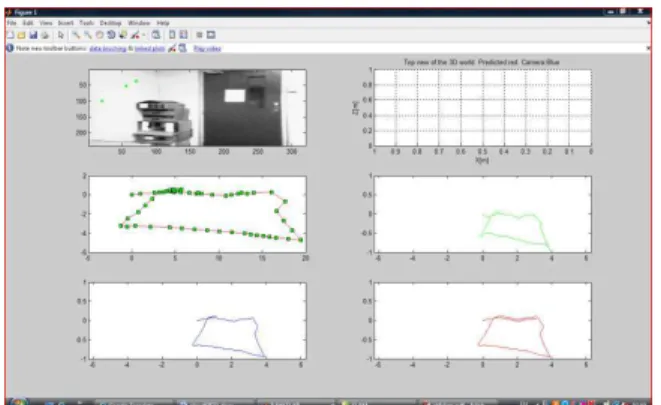
Indoor experiment: The experiment here is done using, Hp laptop with built-in camera held, facing forward and moving towards the door in the room with moderate velocity and returned back to the window in the same room, the approach verify a good result, Fig. 5a shows the frames for the door in the room, while Fig. 5b shows the pathway with features detected by the system, where the Fig. 5b shows four types of lines, the first is red spotted with green, the number of the green spots on the line means the number of the frames processed by the system. The green line indicates the estimation of the pathway by the EKF, while the blue line is the actual pathway that the user take it, finally the red line is the true pathway that the stored in the system SIFT features calculated for the scene and matched with the stored clouds in the database to advice the blind person for the objects in front the camera while navigation. The decision making for the cloud recognition to change the directions is done according to the maximum features matching between the scene and store clouds. The threshold value has been used for the decision determined. The auditory advising comes from two parts one is the view scene and the second comes from pathway, to inform the direction used by the blind person if it is wrong or not. Loop closing experiment: The same experiment is continued with a loop closing within the same room, a handheld camera was carried by a person walking in a loop circle in the environment of the room, the input sequence frames from 1-120 gives the system to circulate around one place in the room as shown in Fig. 6.
Fig. 5a: Frames 15-22 from the 32 frames
Fig. 5b: Map building for the camera pathway (top view)
Fig. 6: Top view animation movement of the handheld camera
When continued looping in the same loop the second loop a drift of 0.5 m disappeared, after investigation of the system, we concluded that the scaling factor is essential introduced inside the system, for each session, this scaling factor is decreased the drift happen inside the system for loop closure navigation. The scaling factor used here for x and y directions, depending on the extent of the session used to navigate; it is listed in Table 1.
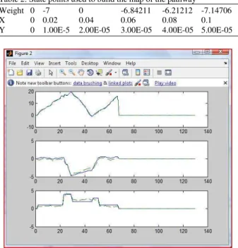
Table 2: State points used to build the map of the pathway Weight 0 -7 0 -6.84211 -6.21212 -7.14706 X 0 0.02 0.04 0.06 0.08 0.1 Y 0 1.00E-5 2.00E-05 3.00E-05 4.00E-05 5.00E-05
Fig. 7: Blue line is actual pathway, green line is estimated pathway by EKF
Figure 6 generated from first loop frames, the scalar weights calculated for the clouds inside these frames, the state points generated for the pathway described in the Table 2 shows the sequences of weights for the frames which is used for generating the pathway of the handheld camera.
So if we storing a true pathway for each session with in the node in advance, then the system will advice the blind person directly to take the true pathway in the session to traverse the nods in the graph.
The calculated weights of scenes environment and cloud construction, will give us the estimated position and the direction of the blind person as a localization process for the system in the graph. The states estimation of the EKF is shown in Fig. 7, shows the convergence between the estimated and the truth path way camera motion, for x, y, th.
DISCUSSION
The system consistently shows good on-line performances for environments, the image for the object stored as features of SIFT to be directly match with the image scene used 320×240 jpg format, low quality with a good rate of correct recognition above 50% depending on the specific environment difficulties. The referencing of the cloud table with in the node is reducing the time for seeking local landmarks, since
the landmarks will be known to the system when recognizing objects in already stored cloud in the table. Referencing one object mean that accessing many objects within the cloud. The good matching of the landmarks is that when the site view with cloud of needed objects, comes in the center of the camera, (i.e., the weight will be high), this will let the system directly recognize the needed objects in the node. Also the site view with more than one cloud is solved when the system select the cloud that have maximum features matching with the scene view.
CONCLUSION
In this study, we described a method that constructing a Map and localizing within the Map, by extracting features from the site view using SIFT algorithm, we established an algorithm to conceptualize the environment using clouds of features with SIFT techniques and advising the true pathway by calculating squared difference between the current pathway and the already stored pathway within the system. the pathway calculating done by calculating the scalar weights of SIFT features of the successive frames checked for generating pathway of the camera motion with helping of clouds to take the direction of moving and locate the objects in the environment, this in turn speed up the localization process within the environment, the model is try to give semantic of the environment due forming these clouds of SIFT features and pathway with the session to navigate with auditory advices from the system. It is also useful to divide the space environment into meaning partitions according grouping objects then it helps to detect sites and objects needed from the blind person in very sufficient way with in the map.
REFERENCES
Abbas, M.A. and J.N. Md, 2009. Vision based reconstruction multi-clouds of scale invariant feature transform features for indoor navigation. J. Comput. Sci., 5: 951-958.
Achar, S. and C.V. Jawahar, 2008. Adaptation and learning for image based navigation. Proceeding of the IEEE 6th Indian Conference on Computer Vision, Graphics and Image Processing, Dec. 16-19, IEEE Xplore Press, Bhubaneswar, pp: 103-110. DOI: 10.1109/ICVGIP.2008.72 Booij, O., Z. Zivkovic and B. Krose, 2005. Pruning the
Booij, O., B. Terwijn, Z. Zivkovic and B. Krose, 2007a. Navigation using an appearance based topological map. Proceeding of the IEEE International Conference on Robotics and Automation, Oct. 10-14, IEEE Xplore Press,
Roma, pp: 3927-3932. DOI:
10.1109/ROBOT.2007.364081
Booij, O., Z. Zivkovic and B. Krose, 2007b. Image based navigation using a topological map. Proceedings of the 13th Annual Conference of the Advanced School for Computing and Imaging, June 2007, Netherlands, pp: 1-8. http://staff.science.uva.nl/~obooij/publications/Boo ij07ASCINavigation/Booij07ASCINavigation.pdf Chwan, H.C. and C. Yung-Pyng, 2007. SIFT based
monocular SLAM with inverse depth parameterization for robot localization. Proceedings of the IEEE Workshop on Advanced Robotics and Its Social Impacts, Dec. 9-11, IEEE Xplore Press, Hsinchu, pp: 1-6. DOI: 10.1109/ARSO.2007.4531427
Civera, J., A.J. Davison and J.M.M. Montiel, 2008. Inverse depth parameterization for monocular SLAM. IEEE Trans. Robot., 24: 932-945. DOI: 10.1109/ROBOT.2007.363892
David, G.L., 2004. Distinctive image features from scale-invarient key-points, cascade filtering approach. Int. J. Comput., 60: 91-110. http://direct.bl.uk/bld/PlaceOrder.do?UIN=150744 203&ETOC=RN&from=searchengine.
Davison, A.J., 2003. Real-time simultaneous localization and mapping with a single camera. Proceeding of the 9th IEEE International Conference on Computer Vision, Oct. 13-16. IEEE Xplore Press, Nice, France, pp: 1403 1410. DOI: 10.1109/ICCV.2003.1238654
Davison, A.J., I.D. Reid, N.D. Molton and O. Stasse, 2007. Mono SLAM: Real-Time Single Camera SLAM. Patt. Anal. Mach. Intell. IEEE Trans., 29: 1052-1067. DOI: 10.1109/TPAMI.2007.1049 Galindo, G., A. Saffiotti, S. Coradeschi, P. Buschka and
J.A. Fernandez-Madrigal et al., 2005. Multihierarchical semantic maps for mobile robotics. Proceedings of the IEEE/RSJ International Conference on Intelligent Robots and Systems, Aug. 2-6, IEEE Xplore Press, USA., pp: 2278-2283. DOI: 10.1109/IROS.2005.1545511
Hub, A., J. Diepstraten and T. Ertl, 2004. Design and development of an indoor navigation and object identification system for the blind. Proceedings of the 6th ACM SIGACCESS Conference on Computers and Accessibility, Oct. 18-20, Atlanta,
GA., USA., pp: 147-152.
http://portal.acm.org/citation.cfm?id=1029014.102 8657
Li, F.F. and P. Perona, 2005. A Bayesian hierarchical model for learning natural scene categories. Proceedings of the IEEE Computer Society Conference on Computer Vision and Pattern Recognition, June 20-26, IEEE Computer Society, San Diego, CA., USA., pp: 524-531. http://portal.acm.org/citation.cfm?id=1069129 Lowe, D.G., 1999. Object recognition from local
scale-invariant features. Proceeding of the 7th International Conference on Computer Vision, Sept. 20-27, IEEE Xplore Press, Kerkyra, Greece, pp: 1150-1157. DOI: 10.1109/ICCV.1999.790410 Miro, J.V., W. Zhou and G. Dissanayake,
2006.Towards vision based navigation in large indoor environments. Proceeding of the IEEE/RSJ International Conference on Intelligent Robots and Systems, Oct. 9-15. IEEE Xplore Press, Beijing,
pp: 2096-2102. DOI:
10.1109/IROS.2006.28248716
Montiel, J., J. Civera and A.J. Davison, 2006. Unified inverse depth parameterization for monocular SLAM. Proceedings of the Robotics: Science and Systems RSS, Aug. 16-19, Philadelphia, PA., pp: 1-1. http://pubs.doc.ic.ac.uk/inverse-depth-slam/
Smith, R., M. Self and P. Cheeseman, 1988. A stochastic map for uncertain spatial relationships. Proceeding of the International Symposium of Robotics Research, The MIT Press, Cambridge, MA, USA., pp: 467-474.