TranslaTing rF ConCepTs in anTenna Theory To The opTiCal Domain
Rui Gomes a1, Maria João Martins a2, António Baptista b, João Torres b
a CINAMIL - Centro de Investigação da Academia Militar, Academia Militar, Lisboa, Portugal b Departamento de Engenharia Eletrotécnica, Instituto Superior Técnico, Lisboa, Portugal
ABSTRACT
Technology plays an increasing role in military operations, altering the paradigm of operations and providing new means for tactical operations, surveillance and tracking of enemy activities and other Security and Defen-se related activities. Antennas play a leading role in this new operational environment since they are key elements in the retrieval of information in its various forms. Nowadays communications are moving to the optical frequencies, due to the extended bandwidth available, and the saturation of the RF spectrum. Antennas’ dimensions are related to the wavelength of the operating frequency, and therefore, building an antenna for the op-tical bandwidth, implies the use of nanotechnology. In this paper the basic concepts of antenna theory will be revised and extended or modified, to accommodate for new realities in the optical domain.
Keywords – Antenna Theory, Optical Frequencies, Radiofrequency
Nano-technology.
RESUMO
A tecnologia desempenha um papel cada vez mais importante em operações militares, alterando o paradigma das operações e fornecendo novos meios para operações táticas, vigilância e seguimento das atividades do inimigo bem como outras atividades ligadas à Segurança e Defesa.. Hoje em dia, as comunicações RF e de microondas estão a sofrer uma migração para as frequências óticas, uma vez que estas proporcionam uma largura de banda muito maior e também porque o espetro de RF já se encontra quase satu-rado. As dimensões das antenas estão relacionadas com o comprimento de onda da frequência de operação e, portanto, a construção de uma antena 1 O presente artigo resultou do trabalho desenvolvido para a Dissertação de Mestrado elaborada pelo autor. 2 Email para contacto: [email protected]
para a banda ótica, implica a utilização da nanotecnologia. Neste trabalho, os conceitos básicos da teoria das antenas serão revistos e ampliados ou modificados, para acomodar as novas realidades no domínio ótico.
Palavras-chave – Teoria de Antenas, Frequências Óticas, Radiofrequência,
Nanotecnologia.
1. INTRODUCTION
Since the pioneering experiments of Heinrich Hertz, which proved the existence of electromagnetic waves, antennas have been used to provide communication between the transmitter and receiver, through space.
Antennas are structures made of metal, whose dimensions are related to the wavelength of operation (Balanis, 2005). The feed point is usually a gap where the connecting devices (transmission line, coaxial cable or waveguide) are connected. In order to guarantee the proper behavior of the antenna, matching conditions are required between the antenna’s input impedance and the connecting device impedance. Matching circuits, made of concentrated parameters (capacitors inductances and resistances) or made of line sections, usually called stubs, are designed to fulfill the matching conditions (Martins & Neves, 2015).
When optical antennas are considered several of these well-established concepts disappear. Metals behave as good and almost perfect conductors through the RF spectrum; however in optical frequencies they can become transparent to the incident radiation, and so they can no longer be considered as perfect conductors (Novotny L. , 2011). In the next section the behavior of metals will be studied as a function of the operating frequency.
2. THE DRUDE-SOMMERFELD MODEL FOR METALS
The Drude-Sommerfeld model describes the movement of the free electrons, inside the metal, which is assumed neutral since the charge of the electrons is compensated by the charge of the ions. Since the ions’ mass is much lar-ger than that of the electrons (the mass of the proton is around 1840 times larger than the mass of the electron), the ions are considered static. The equation of movement of the free electrons is as follows (Novotny & Hecht, 2006): (1)
where e and me are the charge and effective mass of the free electron, and
E0 and ω are the amplitude and frequency of the incident electric field. The
damping coefficient is represented by Γ=υF⁄l, where υF represents the Fermi
velocity and l is the mean free path between collisions. By solving equation (1), the following equation results: (2) where ωp = √(n e2/(m
eε0) is the plasma frequency.
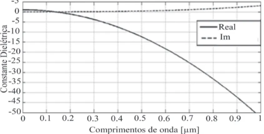
In figure 1, the real and imaginary parts of the dielectric permittivity are represented for gold. In this case the plasma frequency and damping coe-fficient are respectively: ωp = 2π∙ 13,8×10¹⁵ rad.s-1and Γ = 1,075×1014 Hz.
Fig. 1. Real and imaginary parts of the dielectric permittivity for gold,
according to the Drude Sommerfeld model
From figure 1, one can conclude that the real part of ε is negative which ac-counts for the anomalous behaviour of dispersion at optical frequencies, whereas the imaginary part remains almost constant with the variation of wavelength. The Drude-Sommerfeld model is valid for wavelengths above 650 nm (infrared frequencies). When operating into the visible part of the spectrum, namely for wavelengths below 650 nm, a correction, taking into account the contribution of the bound electrons, must be considered (Novotny & Hecht, 2006). Thus, equation (1) is modified to:
where m is the effective mass of the bound electron, γ is a loss term whi-ch describes the radiation damping due to the bound electrons and α is a coefficient that describes the elastic force. From equation (3) the following result is derived:
(4) where ωp = √(ñ e2/m
ε0 is the plasma frequency for the bound electrons with
volume density ñ.
In figure 2 the real and imaginary parts of equation (4) are presented as a function of the wavelength of the field, for gold (ω̃p= 2π∙ 45×1014 rad.s-1,
γ = 9×10¹⁴ Hz e ω
0 = 2π c/λ0, com λ0 = 450 nm).
From figure 2, one can observe that there is a resonant behavior for the imaginary part of ε, and a dispersive behavior for the real part.
The oscillations of the free electron gas charges, behave almost as parti-cles, so these clusters of oscillating charges are designated by “Plasmon Polaritons” (Novotny & Hecht, 2006).
Fig.2 Real and imaginary parts of the dielectric permittivity for gold, taking
into account the contribution of the bound electrons.
These plasmons are typical of the light interaction with the nanostructure of the metal and are not present at RF. When the condition of resonance is attained, the corresponding charge structure is designated by “Surface Plasmons Resonance” (SPR).
Optical antennas use the resonance and the plasmonic behavior of metals as the basic mechanisms for enhanced radiation (Wenger, 2011).
These devices represent an enabling technology that can improve the antenna feeding network performance overcoming the limitations of the traditional
technology in the more demanding scenarios. Moreover, integrated optics technology can play a crucial role as an alternative technology for imple-menting beam-forming structures for satellite applications thanks to the well known advantages of this technology such as electro-magnetic interfe-rence immunity, low consumption, low volume and weight, huge electrical bandwidth, low-attenuation remote delivery capability (due to the optical fibre) and the robustness and precision that exhibit the integrated optics, especially in the case of Silicon-on-Insulator, due to the compactness and its compatibility with the standard CMOS technology.
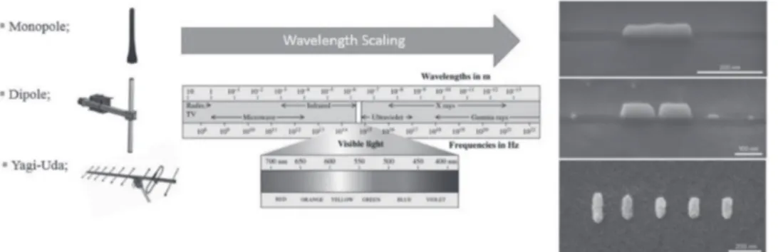
Fig. 3. Optical antennas and their RF and microwave counterparts
In the next section the basic parameters for antennas will be reviewed and their performance in the optical domain is analyzed.
3. REVISION AND REFORMULATION OF ANTENNA’S PARAMETERS 3.1 raDiaTion eFFiCienCy
This parameter describes the ration between the power radiated by the an-tenna and the power delivered to its terminals.
(5)
It depends on the ability of the antenna to convert into radiated power the input power, which depends also on the power losses. This parameter is a function of the relation between the dimensions of the antenna and the operating wavelength.
3.2 DireCTiviTy
The capacity to focus the radiated power into a narrow beam is described by the directivity. This parameter is closely related to the efficiency of the antenna. The concentration of the radiated power into a given region of the space, allows for an improved communication between transmitter and receiver. Therefore, increasing the directivity allows for a reduction of input power. (6) where the angles θ and φ, represent the direction of propagation, and UM is the maximum value of the radiation intensity, or the power radiated by unit solid angle.
3.3 anTenna gain
This parameter is a combination of efficiency and directivity. The definition is analogous to that of the directivity, but with relation to the input power instead of the radiated power.
(7)
In the RF band it is usual to refer the Gain to a reference isotropic antenna, and the Gain is then expressed in dBi.
In optical frequencies, according to (Kausar, et al. 2015), isotropic antennas are not good references, so another optical antenna should be considered as reference for the gain.
3.4 anTenna aperTure
The antenna aperture is closely related to an “effective” area. It is a concept with a direct connection to receiving antennas. However the application of the Reciprocity Principle allows its extension to transmitting antennas. (8)
In this expression σ0 is the effective cross section of the antenna and E0 is the incident field at the receiver.
For optical antennas improvement factors of the order of 104-105, have been
obtained for molecules with σ0 = 1nm2 and a spacing of 0,1-1µm between
molecules (Kausar, et al. 2015).
3.5 loCal DensiTy oF eleCTromagneTiC sTaTes (lDos)
One of the most important parameters is the antenna’s impedance. According to circuit theory, impedance is defined as Z = V⁄I, where I is the current and V is the voltage. In this case, it is assumed that the antenna is connected to the source through a transmission line or equivalent device. However, in the case of optical antennas the feeding method is made by confining ligth emmiters rather than real currents. A practical replacement of this definition comprises the LDOS, which is the cause of the dipole energy dissipation in a random inconsistent environment. According to (Kausar, et al. 2015), the allowance of a clear relationship of quantum-conventional formalisms is the main benefit of using the LDOS, which is represented by ρ and the total LDOS can be found as:
(9)
where Tr represents the trace, ρP is the partial LDOS, ω is the transition
frequency, G is the Green function tensor, c is the velocity of ligth, and r0
is an arbitrary location. Therefore, the LDOS accounts for the existence of the antenna and is an extent of its properties. In the absence of an antenna in free space, we achieve ρP=ω2/(π2 c3) and Γ
0 = ω3 | g|p̂|e |2/( 3πε0hc3 ). This
distinct field attains the rear of the position of the atom after scattering in the indigenous surroundings. The transition frequencies and energy states are also affected by this back-action (Kausar, et al. 2015).
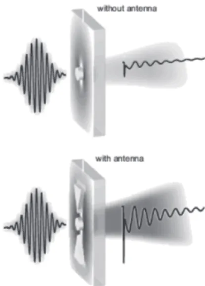
Knowing that optical antennas do not require any power source, an immediate application of these antennas is in wireless optical communication systems, where they can be incorporated in the transmitter or receiver.
Thus, they can be used as a light amplifier, allowing the transmitted or re-ceived light beam to be much narrower, to have a much greater directivity and higher intensity.
In figure 4, this concept is well represented.
Fig. 4. Example of the application of an
optical antenna to enhance light transmission (Schumacher, et al., 2011).
These characteristics are very interesting for military applications, since they allow to transmit more data, more available bandwidth, which implies increased capacity for data transmission, and more secure communications, because the light beam becomes more difficult to intercept.
3.6 anTenna impeDanCe
The antenna resistance can be calculated as Re{Z}=P/I2 , according to circuit
theory. Considering the optical domain and the optical antennas, there exists a governing dipole rather than a physical current, which is more suitable for expressing Z according to the current density, j~iωp , as a replacement for the current, I. Thus, the antenna impedance can be defined by the expression: (10) By equation (10) one can conclude that the antenna resistance Re{Z} can be linked with the LDOS. The unit of antenna impedance is Ohm per area
instead of the typical Ohm. Finally, Z is mutually dependent on the position
r0 and alignment np of the dipole.The stored energy can be found by the
imaginary parto f Z. (Kausar, et al. 2015)
3.7 anTenna resonanCe
The resonantly excited nanostructures behave as optical antennas similar to RF antennas, especially in the IR (infrared) band, and concentrate the energy of electromagnetic radiation to a confined volume of the subwavelength sca-le. According to RF antennas theory, a simple λ/2 dipole has a relationship between L and the resonant wavelength λres given by 2L = λres. However, this relationship does not hold for nanoantennas at optical frequencies. (Kumar, 2011) In fact, for the optical domain this relationship is given by:
(11)
where λp is the plasma wavelength of the antenna’s material, whereas the
coefficients c1 and c2 rely on the diameter of the antenna, D, and on the
dielectric function of the surrounding médium. It must be take into account that D « L, considering the particular case of optical antennas and that the metal is described as a free-electron gas, as stated before by the Drude--Sommerfeld model.
3. CONCLUSIONS
Optical antennas are a new and exciting field for telecommunications en-gineering. Due to the advances in new materials and nanotechnologies it is possible now to build nanostructures providing effective means of commu-nication using the unusual properties of metals in this bandwidth. Optical nanoantennas can be incorporated in garments monitoring the vital parameters of soldiers, they find applications in nanoweapons and nano radars which are no longer a product of science fiction, but are a reality that will soon be incorporated in our daily practice. The challenges that these devices represent for security and defense activities is huge. It is therefore impor-tant to understand the change in this paradigm. In this paper an overview of the translation of usual RF concepts in the optical domain is provided and is, we believe an essential tool for the understanding of these devices.
BIBLIOGRAPHIC REFERENCES
BALANIS, C. A. (2005). “Antenna Theory Analysis and Design”. New Jersey: Third edition, John Wiley & Sons, Inc.
BHARADWAJ, P., DEUTSCH, B., & NOVOTNY, L. (11 de Agosto de 2009). “Optical Antennas”. Institute of Optics and Department of Physics and Astronomy. Rochester, New York
KAUSAR, A. S., REZA, A. W., LATEF, T. A., ULAH, M. H., & KARIM, M. E. (2015). Optical Nano Antennas: State of the Art, Scope and Challenges as a Biosensor Along Human Exposure to Nano-Toxicology. (M. S. Unlu, Ed.) Sensors, 8787-8831.
KUMAR, A. (2011). Optical Nano-Antennas: Fabrication, Characterization and Applications. Tese de Doutoramento, University of Illinois at Urbana-Champaign, Illinois.
MARTINS, M. J., & NEVES, I. V. (2015). Propagação e Radiação de Ondas Eletromagnéticas. Lisboa: LIDEL.
NOVOTNY, L. (2011). “From near-field optics to optical antennas”. 47-51. Rochester, New York.
NOVOTNY, L., & HECHT, B. (2006). “Principles of Nano-Optics”. (C. B. Online, Ed.) Cambridge: Cambridge University Press.
SCHUMACHER, T., KRATZER, K., MOLNAR, D., HENTSCHEL, M., GIESSEN, H., &, M. (2011). Nanoantenna-enhanced ultrafast nonlinear spectrocopy of a single gold nanoparticle. Nature Communications, 2 J. (2011). “Aperture optical antennas”. Marseille, France.
Rui Gomes is a Lieutenant from the Signal Corps of Portuguese Army. He holds a Master degree in Military Electrical Engineering from the Portu-guese Military Academy.
Maria João Martins Completed the ”Licenciatura” and Doctoral Degree, both at Instituto Superior Tecnico, Lisbon, where she taught as Professor in the Department of Electrical and Computer Engineering. She was an invited Professor in the Universities of Karlsruhe, Germany, (1992) and Rennes I, France (2004), She served as Expert-evaluator for the European Commission, in the 5th and 6th Framework Programs. She is since 2012 Professor in the Military Academy in Lisbon.
António Baptista Completed the ”Licenciatura”, Master and Doctoral Degree, at Instituto Superior Tecnico, Lisbon, where he has been teaching as Professor in the Department of Electrical and Computer Engineering to the present day. João Torres received is Ph.D in 2014 in electrical and computer enginee-ring and his master degree in 2007 in chemistry engineeenginee-ring and applied chemistry, both in Instituto Superior Técnico of the Technical University of Lisbon(TUL), Portugal. He is graduated since 2004 in physics from Science University of Lisbon, Portugal. Currently he is an Assistant Professor with the Department of Electrical and Computer Engineering at Instituto Superior Técnico. In the last years, he has been at the IT—Instituto de Telecomuni-cações belonging to the research group of Applied Electromagnetics.