BJRS
RADIATION SCIENCES
07-02A (2019) 01-13ISSN: 2319-0612
Accept Submission 2019-01-27
Recycling and melting processes for zirconium alloy
machining chips
L. A. M. Reis
a; C. S. Mucsi
a; L. A. T. Pereira
a; M. C. Alencar
a; M. P. Gomes
a;
L. P. Barbosa
a; J. L. Rossi
aaCentro de Ciência e Tecnologia de Materiais/CCTM, Instituto de Pesquisas Energéticas e Nucleares, 05508-000,
São Paulo-SP, Brazil [email protected]
ABSTRACT
The aim of this work was to perform a study on the recycling process of zirconium alloy chips and to show the efficiency of the cleaning process, the quality control, how the compacted electrodes were obtained and the melting process carried out in a vacuum arc re-melting furnace (VAR). The recycling process started with magnetic separation of possible ferromagnetic alloys chips, the washing of the water-soluble cutting fluid, de-greasing with an industrial or commercial solution, followed by rinsing with continuous water flow under high pressure and further drying with a hot air stream. The first evaluation of the process was carried out using chemical analysis via energy dispersive X-rays fluorescence spectrometry (EDXRFS), and it showed an amount of 10 % to 17 % mass of impurities. Due to contamination with ferrous alloy machining chips, the chips were compacted in a custom-made die of square section (40 x 40 x 500 mm3), resulting in
electrodes with 20 % of the apparent density of the original alloy. The electrode was melted in a laboratory scale VAR furnace at the CCTM-IPEN. A massive ingot of 0.8 kg was obtained. The melting of the chips was shown to be feasible in a VAR furnace allowing for the reduction of the storage volume of the machining chips by up to 40 times.
1. INTRODUCTION
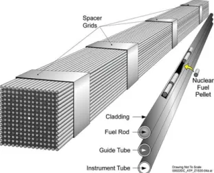
The fuel element used in nuclear reactors of the pressurized-water reactor (PWR) type is generally composed of uranium dioxide pellets (UO2), packaged in zirconium alloy tubes. Due to
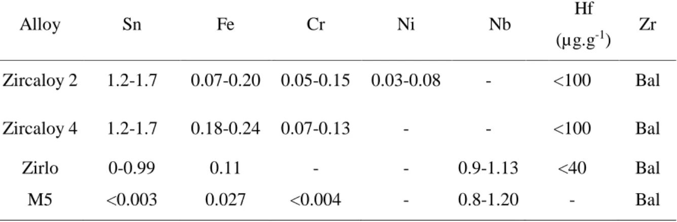
the transparent nature of zirconium to the PWR thermal neutrons and the intrinsic corrosion resistance of the zirconium alloys, these tubes are called fuel rods and are arranged in matrix sets of 14 x 14 to 17 x 17 tubes to form the fuel element (Figure 1). The ends of the fuel rods are sealed with end plugs that can be made of a zirconium alloy of a less restrictive composition. The zirconium alloys commonly used in the tubes and end plugs are known as Zircaloy. But other alloys are also used, see Table 1 [1]. The lathe machining of these parts generates large amounts of machining chip scraps that are contaminated with the cutting fluid and oil. Currently, these alloys are being imported to Brazil, and their reuse is posing a serious challenge to the recycling industries [2].
Figure 1: Fuel rod arrangement description.
Table 1: Chemical composition (mass %) of Zircaloy 2, Zircaloy 4, Zirlo and M5. Alloy Sn Fe Cr Ni Nb Hf (µg.g-1) Zr Zircaloy 2 1.2-1.7 0.07-0.20 0.05-0.15 0.03-0.08 - <100 Bal Zircaloy 4 1.2-1.7 0.18-0.24 0.07-0.13 - - <100 Bal Zirlo 0-0.99 0.11 - - 0.9-1.13 <40 Bal M5 <0.003 0.027 <0.004 - 0.8-1.20 - Bal - Not specified
This work presents the development and the viability study of a process that is used for the recycling of machining chip scraps of zirconium alloys by melting in a VAR furnace. These scraps are usually discarded by the industry because of their high surface to volume ratio. It is a fire hazardous material. And due to their springy nature, it makes them difficult to die-press into usable VAR electrodes.
Based on the historical developments of the fuel elements by the Brazil nuclear Industry (INB), the as-received machining chips were supplied in a non-controlled mix of zirconium alloys and ferrous alloys for this recycling study. The chips generated during the turning operations were stored in plastic drums, which were kept in an exclusive and secluded building due to the pyrophoric nature of the zirconium and large surface to volume ratio. This situation imposed the need for extra caution in the INB facilities, and this is one of the reasons that triggered the interest in this present work. Caution was not taken during the cutting process which made the chips to be contaminated with fluid, so a cleaning process was required prior to the melting process in a vacuum furnace. Usually, the recycling industry has some basic cleaning practices for cleaning the cutting fluid out of ordinary industrial scraps (e.g. aluminium alloys and steels). Centrifugation of the die compaction is the only commercially available cleaning systems that are used in removing large quantities of fluid from scraps, and they can be recycled with the metal alloys [4]. Due to the specific quality and quantities involved, the use of the aforementioned techniques for the cleaning of the chips generated by INB is not adequate for this project, because contamination with ordinary
metals may lead to the failure of the fuel components made from the recycled material.
VAR furnace is the only accepted technology by the nuclear industry for the production of alloys used in nuclear fuel parts [5]. The nature of the VAR furnace is such that the density of the electrodes must be very close to that of the massive alloy to yield useful and economical ingots. Due to the compaction of springy chips which produces an electrode with low relative densities, a modification of the VAR furnace was proposed to tackle this difficulty, and the first results are presented in this paper.
2. EXPERIMENTAL
A cleaning station (Figure 2) has been developed for the removal of fluid contamination from the machining chips. This cleaning route is composed of three plastic vessels. The cleaning processing steps are described as follows:
* Manual magnetic separation with the use of permanent magnets. * Dissolution of the cutting fluid in a water vessel.
* Cleaning with an industrial degreaser.
* Rinsing by high-pressure water washer machine (6.9 MPa). * Hot air continuous flow drying.
Figure 2: Cleaning station for washing of zirconium alloy chips.
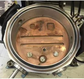
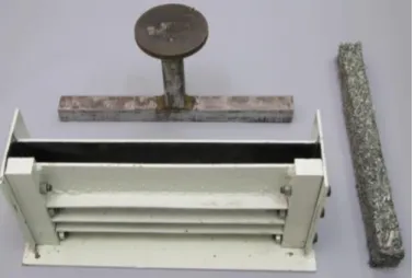
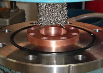
The procedure for the evaluation process was performed using semi-quantitative energy dispersive X-ray fluorescence spectrometer - EDXRFS analysis. Direct and non-destructive tests were performed on the samples. The results obtained were normalized to 100% and converted to the mean and standard deviation estimates for a confidence level of 95%. Three conditions were tested. Some as-received materials were cleaned with magnetic separation, while others were cleaned without magnetic separation. These samples were compacted into a 20 mm diameter die and melted in a non-consumable tungsten electrode electric arc furnace, under a 200 Bar argon atmosphere (Figure 3), designed and constructed with compaction die set of 40 x 40 x 500 mm3 for the preparations of the VAR electrode in a hydraulic press. Approximately 1 kg of clean machining chips were collected for the making of the electrode. The electrode was compacted with a load of 20 ton and has enough axial mechanical resistance to withstand the fixture in the laboratory VAR furnace. Figure 4 shows the developed matrix, and the electrode produced.
Figure 3: Samples placed in the furnace sole. From left to right: as-received material; material
washed with magnetic separation; and material washed without magnetic separation.
Figure 4: Designed and constructed electrode compaction die set and the compacted electrode.
Source: Own authorship
A set of electrodes with increasing compaction loads were obtained to find an ideal compaction condition for the electrode fabrication. Each electrode was melted in a modified VAR furnace installed at IPEN. And the assembly details of the electrode are shown in Fig. 5 [6]. The original furnace allows the melting of massive 550 mm long (450 mm usable) electrodes with diameters ranging from 20 mm up to 35 mm in copper crucibles with 55 mm internal diameter. A maximum DC of 450 A was provided by a rectified power source of 64 V (open circuit voltage). During the melting operation, the pressure in the furnace was obtained by two mechanical vacuum pumps measuring up to 1.10-2 mbar. A set of ten purging operations with argon was performed in order to diminish the quantities of oxygen, nitrogen and hydrogen present in the furnace atmosphere. The modified VAR furnace allows the melting of 40 mm square electrodes in a 30 mm internal diameter crucible [7].
Figure 5: Details of the modification made on the CCTM VAR furnace.
Source: Own authorship
3. RESULTS AND DISCUSSION
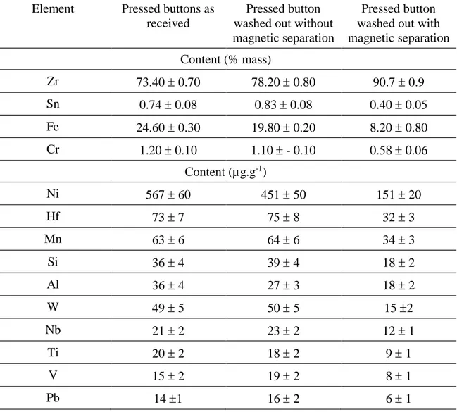
The EDXRFS analyses of samples collected from different batches of as-received chips showed that ferrous alloys contaminated the batches received from INB. This evaluation was also performed on samples cleaned with magnetic separation and those cleaned without magnetic separation [8] (see Table 2). Since this paper deals with the scraps of only one batch, so nothing can be stated about the other batches stored at INB. The magnetic separation performed before the cleaning of the chips resulted in variable amounts of ferromagnetic materials (from 11% up to 17% weight) in the drum. This quantity is important since it will affect the alloy composition after melting, and it will be discussed further.
Table 2: The results of semiquantitative analysis by EDXRFS of the samples in the three
mentioned conditions.
Element Pressed buttons as received
Pressed button washed out without magnetic separation
Pressed button washed out with magnetic separation Content (% mass) Zr 73.40 0.70 78.20 0.80 90.7 0.9 Sn 0.74 0.08 0.83 0.08 0.40 0.05 Fe 24.60 0.30 19.80 0.20 8.20 0.80 Cr 1.20 0.10 1.10 - 0.10 0.58 0.06 Content (µg.g-1) Ni 567 60 451 50 151 20 Hf 73 7 75 8 32 3 Mn 63 6 64 6 34 3 Si 36 4 39 4 18 2 Al 36 4 27 3 18 2 W 49 5 50 5 15 2 Nb 21 2 23 2 12 1 Ti 20 2 18 2 9 1 V 15 2 19 2 8 1 Pb 14 1 16 2 6 1
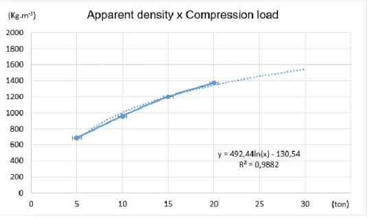
The fact that the material is a mixture of different alloys is critical to the development of the recycling process and can be classified as a material of low-quality scraps. The chips used in this paper is composed mainly of the continuous type and very small amount of the segmented ones [9, 10]. The segmented chips diminish the efficiency of the process because they can loose (when they are on the surface of the electrode) and drop inside the melting pool. Therefore, caution must be taken when mixing the segmented chips with the continuous chips to keep them in the electrode, as this will enhance the efficiency of the process. The apparent density results of the electrodes obtained from the clean chips in a 40 mm square section and 500 mm long die are shown in Figure
6 below.
Figure 6: Plot of apparent density against compression load for obtained electrodes.
Source: Own authorship
The apparent density results obtained from the electrodes ranges from 685 kg.m-3 to 1370 kg.m-3. The tendency curve plotted (Figure 6) on the experimental data showed that there is an estimated increase in the apparent density up to 1544 kg.m-3 for a compression load of 300 kN. This increase in density may lead to a 28 % increase in the furnace capacity.
The compaction movement occurs only in one direction, and due to the springy nature of the chips, the electrode presents a kind of layered feature perpendicular to the press direction. The transversal resistance is severely impaired, so the electrode presented very high flexibility. The mechanical resistance of the electrode is strongly anisotropic being more resistant along its longitudinal axis. This feature shows that it was perfectly adequate to carry out melting in the VAR furnace and during the melting process, the electrode was only subjected to the axial load of its weight. Also, obtaining the electrode for the VAR laboratory furnace is possible and viable. Despite this, there is a need for careful storage to avoid electrode geometrical degradation.
metallic appearances were obtained. The weight of the starting electrode was 914 g and the combined weight of the massive materials was 555 g, that is 60 % of the mass of the starting electrode. The melting operation was deliberately stopped before the total consumption of the electrode. Therefore, the above efficiency figure does not represent the overall process. It is expected that the efficiency level must increase up to 80% when the electrode is melted in the designated length.
Figure 7: Result of the electrode melting described in this paper.
Source: Own authorship
From the product obtained from the melting process, a semi-quantitative elemental characterization was also carried out through EDXRFS analysis, and the results are presented in Table 3. Even when a magnetic separation was performed, the amount of chips required for the melting process was that of the entangled state. Hence, it was not sufficient to reach the iron composition specified in the alloy, and it was necessary to add procedures that would make the process feasible.
Table 3: Results of the semi-quantitative EDXRFS analysis for the product obtained from the
melting process.
Element Content (mass %) Element Content (mass %)
Zr 90.80 ± 0.90 S 0.26 ± 0.03 Fe 5.30 ± 0.50 Al 0.20 ± 0.02 Cr 1.60 ± 0.20 Si 0.05 ± 0.01 Sn 1.20 ± 0.10 Cu 0.04 ± 0.01 Ni 0.62 ± 0.06
4. CONCLUSION
The machining chips of zirconium alloy supplied seemed to have been contaminated with a ferromagnetic material. The contamination makes these chips the secondary-type scrap. This poses some difficulties for the recycling process, thus requiring extra processes and energy consumption (e.g. magnetic separation). This problem was overcome by careful separation and storage of the material before and after obtaining them, thereby, enhancing the quality of the final ingots. The solid products showed a metallic aspect and were very massive. This kind of metallic material can be re-melted, either in an industrial scale VAR furnace or in an Induction Skull Melting (ISM) furnace.
The consolidation process of the zirconium alloy chips by melting in the VAR furnace would allow a 40-fold reduction in the inventory of INB chips, thereby reducing environmental risks and pyrophoric accidents.
Zirconium alloys chips can be melted in a modified VAR process with apparently good results and can also be re-melted either through the VAR furnace or ISM. Also, it is possible to conclude that the recycling process of zirconium alloys chips can be successfully performed on a laboratory scale. Therefore, upscaling of the process is further suggested.
ACKNOWLEDGEMENT
The authors acknowledge CAPES and CNPq for the scholarships to M. P. Gomes and L.A.M. dos Reis respectively, and FINEP for the financial support.
REFERENCES
[1] ATI - Metals. Zirconium alloy. Available at:
<https://www.atimetals.com/zirconium/alloy/isposal_v2.pdf> Last accessed: 02 Aug. 2018.
[2] INB - Brazil Nuclear Industry. Available at:
<http://www.inb.gov.br/ptbr/WebForms/interna2.aspx?secao-_id=105>. Last accessed: 02 Aug. 2018. (In Portuguese)
[3] YUCCA MOUNTAIN. Available at: <https://energy.gov/photos/yucca-mountain> Last accessed: 02 Aug. 2018.
[4] PRAB. Turning chips processing system. Available at:
<http://www.prab.com/metalmachiningscrapequip/chipprocessingsystems.html> Last accessed: 02 Aug. 2018.
[5] GREENFIELD, P. Zirconium in Nuclear Technology. M&B Monograph ME/12 Mills & Boon Limited. London, England 1972.
[6] REIS, L. A. M.; MUCSI, C. S.; ROSSI, J. L. Study on the production of VAR
electrodes from Zircaloy turning lathe chips. VII Scientific Meeting of Applied
Physics, Vitória - ES, Brazil, 2016.
[7] MUCSI, C. S. Proposition of an alternative process to the fusion through VAR
furnace for the consolidation of pressed chips of Zircaloy and study of the dynamic system of the electric arc. Doctorate Thesis in Nuclear technology - Nuclear and Energy
research institute, IPEN-CNEN/SP, São Paulo, Brazil, 2005. (In Portuguese)
ROSSI, J. L.; MARTINEZ, L. G. Chemical and microstructural characterization of
remelted Zircaloy by X-ray fluorescence techniques and metallographic analysis.
Journal of Radioanalytical Nuclear Chemistry, v. 294, i. 2, 2012, p. 283-288. [9] STEMMER, C. E. Cutting tools. Ed. UFSC, Santa Catarina, Brazil, 1989. (In
Portuguese)
[10] MUCSI, C. S.; REIS, L. A. M.; GOMES, M. P.; PEREIRA1, L. A. T.; ROSSI, J. L.
Study on the viability of the recycling by electric arc melting of zirconium alloys scraps aiming the scalability of the process. Materials Science Forum, v. 930, 2017, p.