Effect of CeO
2Doping on Phase Structure and Microstructure of AlCoCuFeMnNi Alloy
Coating
Mingxing Maa , Zhixin Wanga*, Jiachen Zhoua, Cun Lianga, Deliang Zhangb, Dachuan Zhuc
Received: May 05, 2018; Revised: September 29, 2018; Accepted: November 07, 2018
AlCoCuFeMnNi high-entropy alloy coating was prepared by plasma cladding method. The phase structure and microstructure of AlCoCuFeMnNi coating was investigated by XRD, SEM and EDS respectively. The results show that AlCoCuFeMnNi caotings have two BCC phase structure and typical dendrite structure and form good metallurgical bonding with substrate. The dendrite is the typical spinodal decomposition structure. After CeO2 doping, the change of peak intensity and FWHM is obvious due
to the effect of Ce on the improvement of grain growth, microstructure and crystallinity. The addition
of CeO2 is beneficial to reduce the cladding defect, make dendrite arm spacing enlarged and spinodal
decomposition structure refined, and improve element segregation owing to the melioration effect in the temperature gradient, solidification rate, fluidity, wettability, and surface tension.
Keywords: high-entropy alloy, AlCoCuFeMnNi, phase structure, microstructure.
*e-mail: zxwang72@163.com
1. Introduction
As a new idea of alloy design, high entropy alloys (HEAs) break through convention alloy design method in which one or two elements are used as principal element and
have more than five elements as principal element and the
concentration of each element in the range of 5at%-35at%1.
HEAs have a simple solid-solution phase structure, such as face-centered cubic (FCC), body centered cubic (BCC), FCC+BCC, hexagonal close-packed (HCP) lattice, rather than complex intermetallic compounds2,3. At the same time,
HEAs have many excellent properties1-6, such as high strength,
high hardness, high thermal stability, good wear resistance,
high corrosion resistance, etc. As a new frontier in the field
of metal materials, HEAs may exceed the performance limits of convention alloys and have broad application prospects. In 2004, AlxCoCrCuFeNi high entropy alloy was prepared
and the concept of high entropy alloy was first proposed by
Yeh1. Up to now, HEAs research has mainly focused on the
aspects of composition design, mechanical properties, phase structure and so on 6-14. The composition design for HEAs is
primarily based on CoCrFeNi series to add some other alloy
elements to synthesize more than five multiprincipal alloys6-11.
The mechanical properties of HEAs are mainly concentrated on the study of high hardness, high strength, compression and tensile properties and so forth 8-13. The phase structure of
HEAs is chiefly in the terms of phase formation and phase
composition 6-14. It is well known that CeO
2 can play a role
in the purifying to molten alloy, the improvement of alloy
casting properties, the refinement of the microstructure,
and the increasement of alloy hardness and wear resistance for convention alloy 15-17. However, there are few literatures
about AlCoCuFeMnNi high entropy alloy and the effect
of CeO2 on the phase structure and microstructure of high entropy alloys. In this paper, AlCoCuFeMnNi high-entropy alloy coating (HEAC) was prepared by plasma cladding,
and the effect of CeO2 doping on its phase structure and
microstructure were discussed in detail.
2. Experiment
AlCoCuFeMnNi HEAC was fabricated by plasma cladding method. The pure metals of Al, Co, Cu, Fe, Ni and Mn with the particle size of 74 µm and higher purity than 99.5wt% were used as raw materials. The above metal powders having equal molar ratio were put in 304 stainless steel vials with GCr15 balls. Ball-to-powder weight ratio was selected as 10:1. After 2 h ball milling (50rpm), the powder was mixed into gel by organic glue ((97wt% turpentine transdermal alcohol + 3wt% ethyl cellulose). The gel was coated on 45 carbon steel substrates and dried at 120ºC. AlCoCuFeMnNi alloy coating was prepared by the LHD-300 plasma cladding apparatus (137A, 34V, 150mm/min). The preparation process of doped CeO2 alloy sample is exactly the same as that of undoped samples. The purity of CeO2 is 99.9wt%, and its doping ratio is 1 wt%.
The sample was cut into 10mm× 10mm ×5mm block by DK7716 electrical discharge machining (EDM). The crystal structure and phase purity of the synthesized samples
were identified by X-ray diffraction (XRD) analysis using a Rigaku Ultima IV X-ray diffractometer with Cu Kα radiation
aSchool of Materials and Chemical Engineering, Zhongyuan University of Technology, Zhengzhou
450007, China
bSchool of Mechanical Engineering, Northeastern University, Shenyang 110819, China
operated at 40kV and 200mA in the range of 2θ= 30º -90º.
The scanning speed was 8º/min. Metallographic photos were observed by a ZEISS DMM-150C optical microscope. The morphology of the samples was observed in a JSM-6360LV scanning electron microscope (SEM). The chemical compositions of samples were analyzed by Aztec X-Max 90 energy dispersive spectrometry (EDS). All the measurements were performed at room temperature.
3. Results and Discussion
3.1 XRD analysis
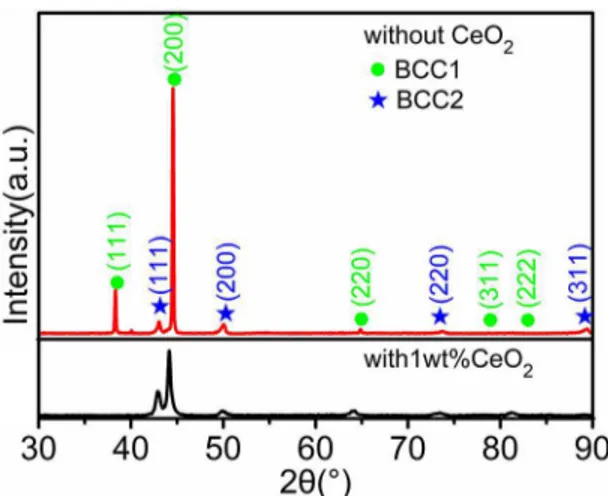
Figure 1 shows the XRD patterns of AlCoCuFeMnNi without and with 1wt% CeO2 HEACs. As can be seen from Figure 1, the phase structures of the two HEACs are composed of BCC1 main phase and BCC2 mixed phase.
The diffraction peaks of BCC1 and BCC2 show their peak positions at about 2θ=38.27º, 44.48º, 64.77º, 78.69º, 82.92º,
and 42.98º, 49.95º, 73.53º, 89.11º, respectively. As shown in Fig. 1, the two-phase structures of AlCoCuFeMnNi coatings are composed of BCC1 and BCC2 phases. The lattice constants are calculated to be 4.0567 Å and 3.6460 Å by linear extrapolation method respectively. Table 1 shows the characteristic parameters of HEAC elements. According to Table 1, the atomic radii of Co, Fe and Mn are basically the same as that of Ni, which is obviously smaller than the atomic radius of Al, Cu and Ce. Besides, the contents of all elements except for Ce are equal. Therefore, the lattice
expansion causes the diffraction peaks to shift toward a
small angular direction 18,19.
Figure 2 shows the diffraction peak area and full
width at half maximum (FWHM) of BCC1 and BCC2 for AlCoCuFeMnNi without and with 1wt% CeO2 HEACs.
The area of diffraction peak is normalized based on that of the strongest peak at 44.48º. Compared with the diffraction peak data of AlCoCuFeMnNi HEACs, the diffraction peak intensity of BCC1 phase decreases significantly, while the
intensity of BCC2 phase increases obviously, and the two BCC FWHM increases obviously for 1wt% CeO2 doping AlCoCuFeMnNi HEACs from Figure 1 and Figure 2. This is because CeO2 addition is helpful to improve temperature
gradient, solidification rate, fluidity, and wettability of the
liquid metal, reduce surface tension, and is also favorable for the formation of low melting point compounds produced by the harmful elements such as sulfur, phosphorus, silicon 15,16.
In addition, CeO2 is easily ionized and released oxygen in high temperature environment. As a surface-active element and spherical element 17, Ce element is beneficial to limit
the grain growth, refine the microstructure and improve
the alloy crystallinity resulting in the change of the peak intensity, peak position and FWHM.
3.2 Microstructure analysis
Figure 3 shows optical microscope (OM) images of AlCoCuFeMnNi alloy without and with 1wt% CeO2 addition. As presented in Figure 3, the two HEACs are dendrite structure, and there is good metallurgical bonding between coating and substrate. Compared with CeO2 undoped sample, there is no hole in the coating and substrate for CeO2 doped sample.
The direction of dendrite growth is mainly affected by the heat flow of molten pool. The growth direction of coating
Figure 1. XRD patterns of AlCoCuFeMnNi without and with 1wt% CeO2 HEACs
Table 1. Characteristic parameters of HEAC elements
Element
Melting point
(℃) Electronegativity
Atomic radius
(nm)
Lattice structure
Al 660 1.61 0.143 FCC
Co 1495 1.88 0.125 HCP/
BCC
Cu 1083 1.90 0.128 FCC
Fe 1535 1.83 0.127 BCC/
FCC
Mn 1244 1.55 0.126 BCC
Ni 1453 1.92 0.125 FCC
Ce 798 1.12 0.182 FCC
Figure 2. The diffraction peak area and FWHM of BCC1 and
dendrite tends to be perpendicular to the substrate surface due to the large temperature gradient near the substrate area.
Far away from the substrate area, the heat flux is mainly
controlled by the movement of the plasma beam, which makes the growth direction parallel to the substrate surface. Compared with CeO2 undoped sample, the microstructure of 1wt%CeO2 doped HEAC has lager dendrite arm spacing
and more significant aggregation of the interdendrite phase.
Figure 4 shows SEM images of AlCoCuFeMnNi alloy without and with 1wt% CeO2 addition. As shown in Figure 4, the dendrite regions of the two alloys are a network layered structure, which belongs to the typical spinodal decomposition structure. In order to reduce the coherent lattice strain energy, the growth process of the
supersaturated solid solution is through the
diffusion-segregation mechanism without nucleation directly along to the crystal orientation having lowest energy. This growth process is spontaneously formed the amplitude-modulation
decomposition structure owing to composition fluctuations,
and uniformly occurred with a certain periodic pattern in the alloy system 20. This structure with different component
has different atomic size, which causes the difference of the
lattice constants in the rich and poor solute regions. Table 2 is the EDS analysis results of AlCoCuFeMnNi alloy without and with 1wt% CeO2 addition. From Figure 1 and Table 2,
the two alloys have two BCC phases with the same space
group and the different lattice constant owing to the different
solute concentration, resulting in coherent stress and elastic
interactions. The elastic interaction is beneficial to inhibit
the growth of this microstructure 20,21, and the larger the size
factor was, the more obvious the inhibition was. As can be seen from Table 2, Cu element is mainly concentrated in the interdendrite region, which is the result of the competition of
element electronegativity, atomic radius difference and mixing
enthalpy due to the large positive mixing enthalpy and the poor mutual solubility between Cu and other elements, and the low melting point and the late crystallizing of Cu element. From Figure 4, the spinodal decomposition structure of 1wt%CeO2 doped sample is obviously refined. This is mainly due to: (1) CeO2 is easily ionized to release oxygen under high temperature, and Ce is a surface-active element 15,16. Compared with other alloy elements, there is
obviously large in the atomic radius and relatively low in
the melting point and the diffusion rate for Ce. When the alloy solidifies and crystallizes, most of Ce elements tend
to segregate between interdendritic regions. (2) the alloy
microstructure is refined by the component supercooling and the hindering effect of the rare earth elements on the grain
growth at the grain boundary 17. From Table 2, the Ce content
is higher in the interdendrite region, which is because the
Figure 4. SEM images of AlCoCuFeMnNi alloy without (a, b) and with (c, d) 1wt% CeO2 addition
Table 2. EDS analysis results of AlCoCuFeMnNi alloy without and with 1wt% CeO2 addition
Alloy Region Mole fraction/at%
Al Co Cu Fe Mn Ni Ce
AlCoCuFeMnNi
Nominal 16.67 16.67 16.67 16.67 16.67 16.67
-DR 23.14 17.76 13.18 25.74 10.32 9.86
-ID 15.36 11.19 24.92 11.75 17.67 19.11
-AlCoCuFeMnNi + 1wt%CeO2
Nominal 16.36 16.36 16.36 16.36 16.36 16.36 1.84
DR 22.47 17.15 13.91 21.95 11.96 11.34 1.22
ID 16.03 11.96 21.99 14.75 16.48 16.86 1.93
melting point of Ce is relatively low, and the atomic radius
is obviously different compared with other elements. It is difficult to enter into the lattice sites of other metal elements
under the low crystallizing driving force, so most of Ce element is easy to occupy the interdendrite regions.
3.3 Phase transformation analysis
As can be seen from Figure 1, the microstructures of AlCoCuFeMnNi alloy without and with 1wt% CeO2 addition are composed of two phase structures. The BCC-phase preferential precipitation, rather than intermetallic compounds, is mainly determined by high mixing entropy
effect of multiprincipal alloy systems. According to the
Gibbs free energy law, the alloy mixing entropy ΔSmix and the mixing enthalpy ΔHmix can be expressed 22:
(1)
(2)
(3)
(4)
Where ΔGmix is Gibbs free energy, T is the thermodynamic temperature, ΔSmix is the mixing entropy, R is the gas constant,
ci is the molar percentage of the i-th component in the alloy
G
mixH
mixT S
mixD
=
D
-
D
ln
S
mixR
c
ic
i in
1
D
=-=
/
H
c c
,
mix ij i j
i i j
n
1
D
=
X
!
=
/
H
4
ij AB
mix
system, and Ωij is the interaction parameter between i and
j component, and HABmix
D is calculated using the Miedema model through A-B mixing enthalpy, which can be obtained in reference 23. From equations (1) to (4), the mixing enthalpy,
mixing entropy, and Gibbs free energy during the alloy phase transformation can be calculated as shown in Table 3.
Table 3. Mixing entropy, mixing enthalpy, and Gibbs free energy of the alloy
Alloy ΔHmix (kJ/
mol)
ΔSmix
(J/K·mol)
ΔGmix (kJ/
mol)
AlCo -19.00 5.76 -20.72
AlCu -1.00 5.76 -2.72
AlFe -11.00 5.76 -12.72
AlMn -19.00 5.76 -20.72
AlNi -22.00 5.76 -23.72
CoCu 6.00 5.76 4.28
CoFe -1.00 5.76 -2.72
CoMn -5.00 5.76 -6.72
CoNi 0.00 5.76 -1.72
CuFe 13.00 5.76 11.28
CuMn 4.00 5.76 2.28
CuNi 4.00 5.76 2.28
FeMn 0.00 5.76 -1.72
FeNi -2.00 5.76 -3.72
MnNi -8.00 5.76 -9.72
AlCoCu -6.22 9.13 -8.94
AlCoFe -13.78 9.13 -16.50
AlCoMn -19.11 9.13 -21.83
AlCoNi -18.22 9.13 -20.94
AlCuFe 0.44 9.13 -2.28
AlCuMn -7.11 9.13 -9.83
AlCuNi -8.44 9.13 -11.16
AlFeMn -13.33 9.13 -16.05
AlFeNi -15.55 9.13 -18.27
AlMnNi -21.77 9.13 -24.49
CoCuFe 8.00 9.13 5.28
CoCuMn 2.22 9.13 -0.50
CoCuNi 4.44 9.13 1.72
CoFeMn -2.66 9.13 -5.38
CoFeNi -1.33 9.13 -4.05
CoMnNi -5.78 9.13 -8.50
CuFeMn 7.56 9.13 4.84
CuFeNi 6.67 9.13 3.95
CuMnNi 0.00 9.13 -2.72
FeMnNi -4.44 9.13 -7.16
AlCoCuFe -3.25 11.53 -6.68
AlCoCuMn -8.50 11.53 -11.93
Alloy ΔHmix (kJ/
mol)
ΔSmix
(J/K·mol)
ΔGmix (kJ/
mol)
AlCoCuNi -8.00 11.53 -11.43
AlCoFeMn -13.75 11.53 -17.18
AlCoFeNi -13.75 11.53 -17.18
AlCoMnNi -18.25 11.53 -21.68
AlCuFeMn -3.50 11.53 -6.93
AlCuFeNi -4.75 11.53 -8.18
AlCuMnNi -10.50 11.53 -13.93
AlFeMnNi -15.50 11.53 -18.93
CoCuFeMn 4.25 11.53 0.82
CoCuFeNi 5.00 11.53 1.57
CoCuMnNi 0.25 11.53 -3.18
CoFeMnNi -4.00 11.53 -7.43
CuFeMnNi 2.75 11.53 -0.68
AlCoCuFeMn -5.28 13.38 -9.27
AlCoCuFeNi -5.28 13.38 -9.27
AlCoCuMnNi -9.60 13.38 -13.59
AlCoFeMnNi -13.92 13.38 -17.91
AlCuFeMnNi -6.72 13.38 -10.71
CoCuFeMnNi 1.76 13.38 -2.23
AlCoCuFeMnNi -6.78 14.90 -11.22
During the plasma cladding process, the HEAC elements are in the state of multicomponent mixed liquid metal. With the moving of plasma beam, the temperature of the HEAC
melt decreases and gradually reaches the solidification
temperature. Firstly, the HEAC element with high melting point (such as Fe(1535ºC), Co(1495ºC), Ni(1453ºC) (see Table 1)) depends on the nucleation and growth of impurity particles and generates some transition phases according to the competition results of the mixing enthalpy, the crystal structure, the chemical compatibility and the free energy as shown in Table3 and Figure 5. The lattice structure of Co is HCP structure below 417ºC and BCC structure above 417ºC 24. When liquid alloy solidifies, Co has FCC structure.
The Fe liquid metal undergoes A4 transition at 1394ºC and changes from BCC to FCC. At 912ºC, the A3 transition occurs and phase transformation changes from FCC to BCC
again. The kinetic coefficient of BCC is larger than FCC,
but the associated kinetic anisotropies are quite similar 25.
The structural transformation is beneficial to the bonding between Fe and the alloy elements with different crystal
and nucleate around the primary phase, because the diffusion
distance of the alloying elements increases with further growth
of the primary phase in the solidification progress and the diffusion rate decreases significantly with the temperature
decreasing. Therefore, Mn and Cu elements precipitate and
have a larger diffusion rate from the liquid metal and easily
attach to the nucleation in the particle surface of the primary
phase. Under the effect of solute redistribution, the alloy
phase can alternatively grow in order to reduce the distance
required for further growth. Meanwhile, the difference of the mixing enthalpy between elements has an important influence
on the formation of solid solutions for multiprincipal alloy system. There is a large positive mixing enthalpy between
Cu and other elements or compounds and different from
the crystal structure of Fe, Co and Ni (see Table 3 and
Figure 5), which is difficult to generate alloy phase with high
solid solubility and is Cu-rich region in the interdendrite (see Table2). With the further decrease of HEAC temperature, Al begins to precipitate from liquid phase and participate in the formation of solid solution phase. From table 3, there is a large negative enthalpy between Al and Ni, Fe, Co, Mn and their compounds, so Al is easy to combine with them to form the stable phase with low free energy. At the same time, because Al is the only alloy element with negative enthalpy with Cu and has the same crystal structure, and the atomic radius is relatively close between Al and Cu compared with other elements. Therefore, Al is relatively easy to combine with Cu than the other three elements, which is in accordance with EDS analysis results of Table 2. After CeO2 doping,
the segregation of alloy elements is significantly improved owing to the melioration effect in the temperature gradient, solidification rate, fluidity, wettability, and surface tension
as mentioned above and reported in the literature 15-17,26.
4. Conclusions
1. AlCoCuFeMnNi HEAC was fabricated using plasma cladding with mixed powders preplaced on the 45-carbon steel substrate. The alloy coating has two BCC phase structure and typical dendrite structure.
2. Ce element is easy to occupy the interdendrite regions, and the addition of CeO2 is beneficial to reduce the cladding defect and make dendrite arm spacing enlarged and spinodal decomposition
structure refined.
3. After CeO2 doping, the segregation of alloy element
is significantly improved owing to the melioration effect in the temperature gradient, solidification rate, fluidity, wettability, and surface tension.
5. Acknowledgements
This work was supported by the National Natural Science Foundation of China (No.51271115), the Ministry of Business, Innovation and Employment (MBIE), New Zealand
(No. UoWX0802), the Scientific and Technological Project
of Chongqing, China (No. CSTC, 2009AB4171), and the Innovation Foundation for Technology Based Firms of Ministry of Science and technology, China (No.04C26225100807)
6. References
1. Yeh JW, Chen SK, Lin SJ, Gan JY, Chin TS, Shun TT, et al. Nanostructured High-Entropy Alloys with Multiple Principal Elements: Novel Alloy Design Concepts and Outcomes.
Advanced Engineering Materials. 2004;6(5):299-303.
2. Feng B, Widom M. Elastic stability and lattice distortion of refractory high entropy alloys. Materials Chemistry and Physics. 2018;210:309-314.
3. Ma MX, Wang ZX, Zhou JC, Liang C, Zhao C. Phase structure of multiprincipal component AlCoCuFeMnNi alloy prepared by melting casting. International Journal of New Developments in Engineering and Society. 2017;1(3):111-114.
4. Lin CW, Tsai MH, Tsai CW, Yeh JW, Chen SK. Microstructure and aging behaviour of Al5Cr32Fe35Ni22Ti6 high entropy alloy.
Materials Science & Technology. 2015;31(10):1165-1170.
5. Gludovatz B, Hohenwarter A, Catoor D, Chang EH, George EP, Ritchie RO. A fracture-resistant high-entropy alloy for cryogenic applications. Science. 2014;345(6201):1153-1158.
6. Meng GH, Lin X, Xie H, Yue TM, Ding X, Sun L, et al. The
effect of Cu rejection in laser forming of AlCoCrCuFeNi/Mg
composite coating. Materials & Design. 2016;108:157-167.
7. Li DY, Li CX, Feng T, Zhang Y, Sha G, Lewandowski JJ, et al. High-entropy Al0.3CoCrFeNi alloy fibers with high tensile strength and ductility at ambient and cryogenic temperatures.
Acta Materialia. 2017;123:285-294.
8. Gwalani B, Soni V, Lee M, Mantri SA, Ren Y, Banerjee R. Optimizing the coupled effects of Hall-Petch and precipitation
strengthening in a Al0.3CoCrFeNi high entropy alloy. Materials & Design. 2017;121:254-260.
9. Niu SZ, Kou HC, Wang J, Li JS. Improved tensile properties of Al0.5CoCrFeNi high-entropy alloy by tailoring microstructures.
Rare Metals. 2017;8:1-6. Figure 5. Crystal structure of BCC(a) and FCC(b) phase in alloy
10. Huo W, Zhou H, Fang F, Hu X, Xie Z, Jiang J. Strain-rate effect
upon the tensile behavior of CoCrFeNi high-entropy alloys.
Materials Science and Engineering: A. 2017;689:366-369.
11. Tazuddin, Biswas K, Gurao NP. Deciphering micro-mechanisms of plastic deformation in a novel single phase fcc-based MnFeCoNiCu high entropy alloy using crystallographic texture.
Materials Science and Engineering: A. 2016;657:224-233.
12. Abuzaid W, Sehitoglu H. Plastic strain partitioning in dual phase Al13CoCrFeNi high entropy alloy. Materials Science and Engineering: A. 2018;720:238-247.
13. Wang J, Guo T, Li J, Jia W, Kou H. Microstructure and mechanical
properties of non-equilibrium solidified CoCrFeNi high entropy
alloy. Materials Chemistry and Physics. 2018;210:192-196.
14. Rao JC, Diao HY, Ocelik V, Vainchtein D, Zhang C, Kuo C, et al. Secondary phases in AlxCoCrFeNi high-entropy alloys: An in-situ TEM heating study and thermodynamic appraisal.
Acta Materialia. 2017;131:206-220.
15. Wang C, Yu Z, Li Q, Yu H, Yu K. Influence of Ceric Oxide
Addition on the Microstructure and Wear Resistance of Laser Remelted M80S20 Alloy Coating. Tribology. 1997;17(1):17-24.
16. Cheng XY, Feng YS, He J. Influence of CeO2 on Microstructure
and Microhardness of TiC4 Coating Produced by Laser-Cladding.
Materials for Mechanical Engineering. 2010;34(1):20-23.
17. Pan YJ, Xu BP, Zhang XJ, Wu XJ. Effects of RE on Ni-based
Metal-ceramic Coatings by Laser Cladding. Journal of Wuhan Yejin University of Science and Technology. 2003;26(1):8-11.
18. Ma MX, Zhu DC, Zhao C, Han T, Cao SX, Tu MJ. Effect
of Sr2+ -doping on structure and luminescence properties
of BaAl2Si2O8:Eu2+ phosphors. Optics Communications.
2012;285(5):665-668.
19. Ma MX, Zhu DC, Zhao C, Han T, Tu MJ. Luminescence properties of Eu2+ doped BaAl
2Si2O8 phosphor for white
LEDs. Science China Physics, Mechanics and Astronomy. 2011;54(10):1783-1786.
20. Awasthi A, Anderson W. Amplitude modulation of streamwise velocity fluctuations in the roughness sublayer: evidence from large-eddy simulations. Journal of Fluid Mechanics. 2016;789:567-588.
21. Pi JH, He XC, Wang ZZ. Preparation of high entropy alloy Cu29Zr32Ti15Al5Ni19 with High Glass Forming Ability. Rare Metal Materials and Engineering. 2017;46(7):1810-1814.
22. Zhang Y, Zhou YJ, Lin JP, Chen GL, Liaw PK. Solid-Solution Phase Formation Rules for Multi-Component Alloys. Advanced Engineering Materials. 2008;10(6):534-538.
23. Takeuchi A, Inoue A. Classification of Bulk Metallic Glasses by Atomic Size Difference, Heat of Mixing and Period of Constituent Elements and its Application to Characterization of the Main Alloying Element. Materials Transactions. 2005;46(12):2817-2829.
24. Ma Y, Jiang H, Yang S, Wang C, Liu X. Martensitic Transformation Behavior And Shape Memory Effect of Co-Fe Ferromagnetic Shape Memory Alloys. Rare Metal Materials and Engineering. 2009;38(3):409-412.
25. Sun DY, Asta M, Hoyt JJ. Crystal-melt interfacial free energies and mobilities in fcc and bcc Fe. Physical Review B. 2004;69(17):174103.