Effect of Heat Treatments and SiC Content in the Mechanical Properties and Microstructure
of Self-Lubricating Steels
Nicolás Ignacio Arayaa*, Cristiano Bindera, Aloisio N. Kleina, Gisele Hammesa,
José Daniel Biassoli de Melloa,b, Claudio Aguilarc
Received: July 19, 2017; Revised: September 20, 2017; Accepted: October 05, 2017
The objective of the present work was to study the effect of heat treatments in the microstructure,
graphite nodules and mechanical properties of self-lubricating steels, to achieve this, self-lubricating steels (Fe + 0.45C + 4Ni + 1Mo %wt) and additions of 2 and 3 %wt SiC were fabricated. They were
consequently heat treated in 3 different conditions: martempering at 180 °C and tempering at 530 °C and 300 °C respectively and austempering at 300 °C. Hardness, yield strength, tensile strength and
work hardening behavior were studied in as-sintered and heat-treated samples. The microstructure was analyzed by optical microscopy, scanning electron microscopy, Raman spectroscopy and micro-hardness. The transformation temperatures were determined using dilatometric tests. Results show
that the presence of dissolved Si in the matrix due to SiC dissociation notably affects the morphology of the microstructure and transformation temperatures also affecting post heat treatment mechanical properties. The structure of graphite nodules produced by SiC dissociation is nott significantly affected
by the heat treatments.
Keywords: heat treatment, metal injection molding, plasma sintering, self-lubricating steel.
*e-mail: [email protected]
1. Introduction
In engineering a recurrent topic for research is the development of materials with a good combination of mechanical properties, heat resistance, high wear resistance,
high corrosion resistance and low specific weight. When such
materials are put into contact and relative motion, a tribological component adds up as minimizing energetic and economical
losses due to deficient lubrication becomes an important
issue for both companies and researchers. For applications
were fluid lubrication is unsuitable (extreme temperatures,
near vacuum pressures, contamination-free environments, etc) solid lubricants and self-lubricating materials appears to be an appropriate alternative or even the only alternative to operate under such conditions1.
Currently several different methods have been developed
for the application of solid lubrication, for example, it can be provided by deposited DLC layers2,3, BCN4, polymer based
composite layers5, etc. Solid lubrication can also be provided
by incorporating solid lubricant into the bulk material by powder pressing6,7 or Powder Injection Molding (PIM)8.
In this context the authors of this paper have developed self-lubricating sintered steels produced by Metal Injection
Molding (MIM)9 and studied its mechanical properties and
tribological behavior10,11. Through MIM it is possible to obtain a fine microstructure consisting of a steel matrix with
homogenously distributed graphite nodules. The graphite nodules come from the addition of silicon carbide (SiC) which dissociates into the ferrous matrix leaving rings of stabilized ferrite surrounding a graphite nodule. This SiC dissociation and graphite formation provides a stock of solid lubricant
which forms a fine graphite rich tribo-layer when the material
is put into contact and relative motion with another surface, thus providing lubrication12. This graphite has been found to
be turbostratic13: turbostratic graphite consist of disordered
graphene layers with random parallel stacking without three dimensional order14. Turbostratic graphite provides lower friction coefficients than crystalline graphite as found by
Kumar et al.15 this explains the low friction coefficients and
wear rates found by previous studies11,16 therefore, studying
the structural changes in these nodules became relevant to evaluate the feasibility to perform heat treatments and retain or improve the tribological behavior of these materials.
Besides contributing to the formation and degradation of the tribolayer, the microstructure of the metallic surface
has a large influence on the tribological behavior of any
material as wear resistance depends on the appropriate combination of strength, ductility and fracture toughness17. aLaboratório de Materiais, Centro Tecnológico, Universidade Federal de Santa Catarina, Campus
Reitor João David Ferreira Lima, s/n , Trindade, 88040-900, Florianópolis, SC, Brazil bLaboratório de Tribologia e Materiais, Universidade Federal de Uberlândia, Av. João Naves de Ávila,
2121, Santa Mônica, 38400-902, Uberlândia, MG, Brazil
cDepartamento de Ingeniería Metalúrgica y de Materiales, Universidad Técnica Federico Santa María,
However, the effect of the ferritic Si enriched zones in the
hardenability, transformation temperatures and mechanical properties have not been studied yet, thus the objective of
this work is to study the influence of the heat treatments on
the microstructural evolution and mechanical properties of these materials and to determine if such heat treatments have an impact in the structure of the graphite nodules that are part of the microstructure.
To conduct the study sintered self-lubricating steels with a Fe + 0.45C + 4Ni + 1Mo steel matrix and additions of 2 and 3%wt. SiC were heat treated and characterized. The
objective of the study was to analyze the influence of the
heat treatments and SiC content in the phase transformations, microstructure, graphite nodules, mechanical properties and
work hardening of these materials. Work hardening was considered of interest as a high work hardening coefficient have been reported to positively influence the wear resistance
under dry sliding conditions in general17 and, in particular, of
ferrous alloys containing graphite nodules18 while decreasing friction itself19. Graphite nodules structure is also of special
interest in regards of the wear resistance and friction
coefficient of these materials20 so Raman spectra is used as
it has proven to be an excellent tool to analyze carbon based materials in terms of crystallinity, bonding and defects21-23
being particularly useful to analyze the presence of defects in carbide derived carbons24.
2. Materials and Methods
Three compositions of sintered steels were used for this study; they consisted of a metallic matrix of Fe + 0.45C + 4Ni + 1 Mo (referred as base alloy) and 2 and 3%wt of SiC.
Table 1 details the powders used and their specifications. Three different feedstocks were prepared consisting in a mixture of metallic and ceramic powders and 8%wt of an organic binder system consisting in paraffin-wax,
polypropylene, stearic acid (surfactant), ethylene vinyl acetate copolymer (EVA) and amide wax. The composition of the binder system is presented in table 2.
A pre-mixture step to homogeneously distribute the binder into the raw material mixture was manually performed using a single container and then the mixing step was done using a
sigma class Haake mixer at 180 °C, 70 RPM for 90 minutes.
After the mixing step the now denominated feedstock was crushed using a Seibt blade grinder.
Tests specimens were injected using an Arburg 320S injection molding machine with a closure force of 50 tf, table 3 shows the main parameters used during the injection process. A two-step chemical debinding process was performed to achieve optimal removal of the polymeric components. The
first step was chemical dissolution of the lower molecular
weight components of the binding system using hexane
heated at 55 °C, first by exposing the samples to hexane
vapor for 2 hours and then by immersing the samples into a hexane bath for 6 hours. To remove the component with higher molecular weight (polypropylene) the plasma assisted debinding and sintering (PADS) process was used25. The
PADS reactor allows the control of processing temperatures and heating rates independently of the plasma parameters. The vacuum chamber contains electrical resistance heaters and thermocouples for heating parameters control and electrodes for DC plasma generation. The samples were put over ceramic insulating plates on the structure of the
anode and were processed using floating potential plasma.
The abnormal hydrogen glow discharge was generated at
a pressure of 133 Pa (1 Torr) and an hydrogen flux of 1000 sccm up to 500 °C. Then a 500 sccm flux was used which
consisted into a mixture of 95% argon (99.999% purity) and 5% hydrogen (99.995% purity).
After sintering, the samples for microstructural characterization were prepared using standard grinding and polishing procedures and the obtained microstructures were observed using a Leica DM - 4000M optical microscope and a JEOL JSM-6390LV scanning electron microscope with an EDS probe attached for chemical analysis. A solution of Nital 2% v/v was used to etch the surface of cross-section samples in order to identify the microstructures, however for the samples of base alloy in the as-sintered condition a solution of Picral 4% v/v was used as it allowed for a
Table 1. Powders utilized in this work.
Element Commercial name Particle mean size (µm) Purity (%wt)
Supplier
Prealloyed Fe + 0.9C (0.45 after sintering)
CL-OM 7.84 98.3 Basf
Ni PF-10F 6.06 99.9 ATMIX
Mo OMP 5.50 99.8 HC
Starck
SiC 800 10.0 99.0 Cobral
Table 2. Binder composition.
Element Mass % of the mixture
%wtof the constituent in the binder
Polypropylene 3.40 42.56
EVA 1.32 16.51
Paraffin 2.90 36.19
Cocamide
DEA 0.36 04.54
Anti-oxidant 0.02 0.20
Total 8.00 100
Table 3. Powder Injection Molding processing parameters.
Injection Pressure (bar) 1000
Settlement Pressure (bar) 800
better identification of the carbides in the microstructure26.
For further microstructural characterization micro-hardness
measurements using Vickers scale according to ASTM E386 standard with a 10g load were performed. A differential dilatometer (NETZSCH DIL 402C) was used to analyze
phase changes at heating and cooling. For these tests samples
taken from 5 different sintered tensile test specimens were used per alloy, with dimensions of 4.8 x 10 mm (diameter x height) the samples were heated at 950 °C for 20 min with a heating rate of 10 °C/min and then cooled at a rate of 10 °C/min up to 100 °C. To obtain the Raman spectra
of the graphite nodules in the samples 3 test specimens per condition were fractured and 5 spectra were obtained using
a Renishaw InVia spectrometer with an Ar laser (λ = 514.5
nm) coupled to a Olympus microscope (BX41 TM). To test mechanical properties 5 samples per condition were tested by uniaxial tension at a strain rate of 0.0067 s-1 according to
MPIF 42 standard and also 10 Brinell hardness measurements per sample were done using a 2.5 diameter tungsten sphere according to ISO 6506.
3. Results and discussion
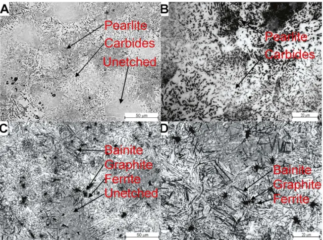
Figure 1 presents the microstructure of the samples of base alloy and base alloy + 3%wt SiC without heat treatment.
The base alloy in the as-sintered condition shows zones of
fine pearlite and ferritic zones with fine precipitated carbides it can be noticed from the figures that when SiC is added,
proeutectoid ferrite surrounding graphite nodules appears. This graphite nodules are formed by carbon coming from SiC dissociation during sintering, the ferrite rings surrounding them is formed because dissolved Si (also coming from SiC
dissociation) stabilize α-iron in the zones where SiC was
present, this dissolved Si also inhibits the precipitation of carbides in the microstructure as discussed in references27-29
also due to Si presence and the reactor cooling conditions regions of bainite can be found in the microstructure.
All the three alloys had white unetched areas. For the base alloy the etched regions (ferrite + carbides) had
a hardness of 2800 ± 264 MPa and the unetched regions had a hardness of 4400 ± 500 MPa, which corresponds to
regions of untempered martensite and austenite due to an incomplete dissolution of nickel.
Fig 2 shows a SEM image of a graphite nodule from the as-sintered sample with 3%wt SiC, the figure shows the chemical composition of both the graphite nodule and the area around it which consist in a region with a high amount of carbon surrounded by a metallic phase with a high content of silicon due to SiC dissociation as it is explained by Binder et al.13.
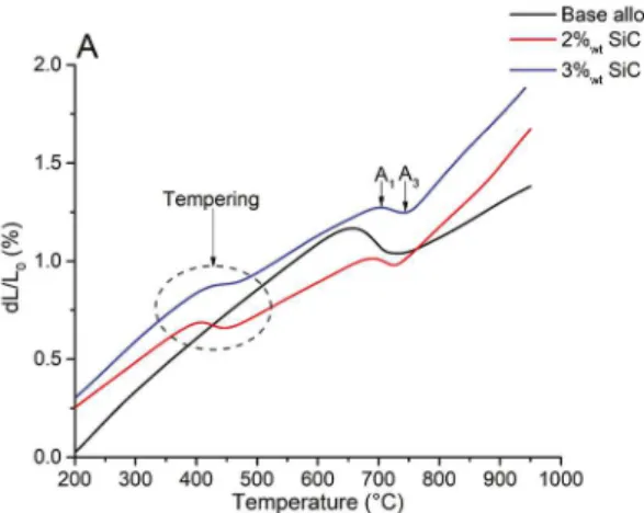
Figs 3 (a) and (b) shows dilatometric curves of heating and cooling for the Fe + 0.45C + 4Ni + 1Mo base alloys with three
different SiC contents. The analysis shows that the samples
with SiC additions undergo a previous transformation prior to ferrite transformation into austenite, this can be attributed to the tempering of martensite and bainite present in the samples in the sintered condition, being this transformation absent in the samples of base alloy without SiC. There is a slight rise of the tempering the tempering temperature from samples with 2%wt SiC to 3%wt SiC, this rise can be attributed to the amount of dissolved Si in the samples as has been previously discussed by Kozeschnik and Bhadeshia28.
Regarding the austenitic transformation, the SiC content decreases the severity of the volumetric change from ferrite to austenite: As part of the microstructure of the SiC containing alloys is stabilized ferrite hence, it doesn't transform into austenite in the A1-A3 range. This can be noticed by analyzing the slope of the curves in the A1-A3 range, while samples of base alloy exhibit a considerable slope in the austenitic transformation range, samples with SiC additions shows a narrow range with a minor slope, hence, a less severe volumetric change. The same applies for the transformation
from γ to α + Fe3C during cooling. Also A1-A3 temperatures are influenced by the Si dissolved in the matrix as a product of the SiC dissociation during sintering: As Si difficult
the transformation of ferrite into austenite30,31 a rise in the
transformation temperatures A1 and A3 is expected. These temperatures are shown in table 4.
Figure 2. SEM image and EDS analysis of a graphite nodule.
Figure 3. Dilatometric curves of heating (a) and cooling (b).
Table 4. Transformation temperatures.
Base alloy Base alloy + 2%wtSiC
Base alloy + 3%wtSiC
A1(°C) 660 +/- 6 690 +/- 6 710 +/- 5 A3(°C) 710 +/- 9 730 +/- 2 750 +/- 8
Silicon dissolved into the matrix due to SiC dissociation also had an impact in the microstructure of the austempered samples. Figure 4 shows the microstructure of austempered samples containing 0, 2 and 3% wt SiC. Samples without SiC shows a regular arrangement of bainite + martensite, however SIC containing samples exhibit larger and coarser bainite grains growing from the ferritic zones surrounding the graphite nodules, this resembles the microstructure found by Malla, Grech and Smallman for high silicon ADI30. Figure 4B
and 4D shows a FE-SEM image of bainite from the samples without SiC and of the acicular ferrite surrounding a graphite nodule of a sample with 3% wt SiC. As silicon is a ferrite stabilizer it can be expected that acicular ferrite nucleation during austempering starts from the Si rich zones (which in this case is the area surrounding a graphite nodule) and then grow into the retained austenite, this results into a coarser and more unevenly distributed mixture of ferrite-austenite which explains the drop in the mechanical properties of the austempered samples with SiC additions that is shown
in figure 5.
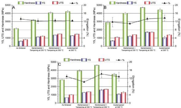
Figure 5 shows the mechanical properties obtained by heat treating samples of the base alloy and samples with additions of 2 and 3 % wt SiC. For all the alloys, as expected, decreasing the tempering temperature increases the mechanical resistance and, in general, the addition of SiC to the base alloy improves its mechanical properties by increasing the hardness and mechanical strength without a considerable decrease of the ductility. It should be noticed
that there are two effects that have to be considered, on one
Figure 4. Optical (OM) and electronic (SEM) micrographs of the austempered samples corresponding to: (A) OM of base alloy (B) OM of base alloy + 3 %wt SiC (C) SEM of base alloy (D) SEM of base alloy + 3 %wt SiC.
causes solid solution hardening and an increment in the hardenability32, on the other hand the zones with a high amount
of Si remains ferritic which is ductile33 this explaining the positive impact of SiC in the hardness and ductility. However,
for the austempered samples the trend is reversed: without
great differences in ductility the hardness and mechanical
resistance decreases with SiC additions. Generally, Si additions into bainite produces an increase into hardness and the other mechanical properties of steels as stated in34
and also reported by35. However, as the same austempering
treatment were performed in the 3 alloys, disregarding the SiC content, Si dissolution into the matrix caused a deviation on the kinetics of the bainite formation, therefore resulting into a coarser and less homogenous microstructure which is detrimental to the mechanical properties.
To better understand the effect of SiC in the mechanical
properties of these alloys the work hardening behavior was studied: several work hardening models have been developed
to fit experimental stress - strain data into a mathematical
model where one or more work hardening exponents can be extracted36. The Hollomon equation is regarded as the
most simple and practical way to obtain this parameter.
The Hollomon work hardening exponent (n) is calculated according to equations 1, 2 and 3:
(1)
Where;
(2)
(3)
Being S the engineering stress and e the engineering
strain. However a deviation from this behavior had been
reported at low and high strains37,38. Nevertheless calculations of instantaneous n values over true strain has proven to be a good method to analyze the behavior of steels with mixed microstructures allowing to compare the work hardening exponents and plastic deformation obtained39. An instantaneous n value means that the work hardening coefficient is calculated
for each step of plastic deformation, this can be deduced from equation (1) as shown by Zhang et al.39.
(4)
Where ni, σi and εi are the instantaneous work hardening exponent, the true stress and true strain respectively39. Figure
6 a, b and c shows the instant work hardening exponent (n) for Fe + 0.45C + 4Ni + 1Mo sintered steel with additions
of 2 and 3%wt SiC under as-sintered, martempered and
tempered at 300°C, martempered and tempered at 530°C
and austempered conditions.
Instantaneous work hardening exponent v/s true strain plots shows that steels with additions of SiC exhibits larger plastic strain and work hardening than the base alloy due to the presence of stabilized ferrite and dissolved
Si originated from SiC dissociation being this effect
previously reported by Cai et al. for ferrite-bainite dual phase steels35 and by Zhou et al. for ferrite-martensite dual
phase steels40. The as-sintered and austempered samples show larger strains and work hardening coefficients than
the martempered samples, SiC additions increase these
differences thanks to the effect of Si in the ductility of
the alloys as previously discussed.
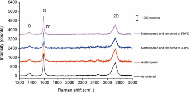
Raman spectroscopy was used to analyze the influence of
the heat treatment in the turbostratic structure of the graphite nodules. Figure 7 shows the Raman spectra of graphite nodules from the base alloy + 3%wt SiC in the as-sintered and heat-treated conditions. The spectra shows the G band at
1580 cm-1 which corresponds to a first order mode with E 2g
symmetry being typical for graphite materials, the disorder induced bands D and D' at 1360 and 1620 cm-1 respectively
which corresponds to double resonance processes which are inhibited in defect-free graphite41 and finally the 2D band
which is a second order resonance mode which varies with the number of graphene layers and the stacking order of such layers.
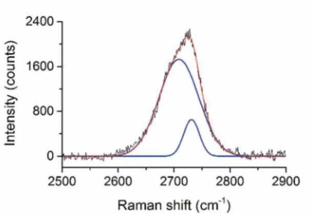
Figure 8 shows a 2D band of an as-sintered sample which
is adjusted by two Lorentzian peaks, the presence of two peaks within the bands indicates a transition process between a turbostratic structure common to carbide derived carbons (CDCs) to a more crystalline structure which is known to
present two well defined peaks within the 2D band42. All
the samples show the same peaks, the presence of D and D' bands indicates the presence of defects which is expected in graphitic materials derived from carbides43-45. The intensity
ratio ID/IG has been largely used to measure crystallite size and to compare the quantity of defects in graphitic samples. Figure 9 shows a plot of ID/IG ratio for the samples in the as-sintered and heat-treated conditions.
Statistical analysis of the ID/IG ratios shows that there
is no statistically significant difference between the samples as determined by one-way ANOVA (F(3,56) = 1.769, p =
0.05) which means that even if the means of the ID/IG ratio
differs between conditions it cannot be concluded with a 95% confidence that the heat treatments had an impact on
the structure of the graphite nodules measured by Raman spectroscopy, therefore, for these materials, heat treatments can be used to improve the mechanical properties of these
materials without significantly affecting the turbostratic
K
nv
=
f
True Stress
v
=
S
Q
1
+
e
V
ln
True Strain
f
=
Q
1
+
e
V
n
d
d
i i i i iv
f
f
v
Figure 6. Instantaneous work hardening exponents (n) v/s true strain for: (A) Base alloy, (B) Base alloy + 2%wt SiC and (C) Base alloy + 3%wt SiC.
Figure 8. 2D band from a graphite nodule of a sample of base alloy + 3 %wt SiC fitted by two Lorentzian peaks.
Figure 9. ID/IG ratios for samples of base alloy + 3 %wt SiC in the as-sintered and heat-treated conditions.
structure of the graphite derived from SiC dissociation10
thus maintaining its ability to provide solid lubrication16.
4. Conclusions
Sintered self-lubricating steels were produced by powder injection molding and plasma assisted debinding and sintering. These were heat treated and its mechanical properties and microstructural evolution were studied. From these studies, it was found that:
• SiC addition to the base alloy decreases the severity in terms of volumetric changes of the transformation
γ ↔ α + Fe3C.
• Si dissolution into the matrix rises the A1 temperature due to ferrite stabilization, it also
modifies the microstructure of the specimens, not
only by generating highly stabilized ferrite zones around graphite nodules but also by modifying the morphology of the matrix's microstructure after
heat treatment. This is particularly noticeable in the austempered samples where dissolved Si generates coarser bainite grains which are detrimental for the mechanical properties.
• SiC addition improves mechanical resistance for all the samples with a maximum at 2%wt SiC. This trend is reversed for austempered samples as its microstructure is coarser than the one found in the samples without SiC due to Si dissolved into the
matrix. Also SiC addition greatly influences the
plastic strain and work hardening exponents due to ferrite stabilization and dissolved Si.
• The presence of the D and D' band in the Raman spectra of the graphite nodules indicates the presence of defects and disorder in the structure of these
nodules, this is further confirmed by the shape of
the 2D band which does not corresponds with a perfectly crystalline graphite.
• Heat treatments don't significantly affect the structure of the graphite nodules generated by SiC dissociation.
5. Acknowledgements
The authors acknowledge the following Brazilian agencies for funding this research: CNPq, Capes, BNDES as well as EMBRACO.
6. References
1. Stachowiak GW, Batchelor AW. Solid lubrication and surface treatments. In: Stachowiak GW, Batchelor AW. Engineering Tribology. 3rd ed. Oxford: Butterworth-Heinemann; 2006. p.
419-459.
2. Özmen Y, Tanaka A, Sumiya T. Effect of humidity on the tribological behavior of diamond-like carbon (DLC) film coated on WC-Co by physical vapor deposition method. Surface and Coatings Technology. 2000;133-134:455-459.
3. Zhang D, Shen B, Sun F. Study on tribological behavior and
cutting performance of CVD diamond and DLC films on
Co-cemented tungsten carbide substrates. Applied Surface Science
[Internet]. 2010 Feb [cited 2014 Oct 6];256(8):2479-2489.
Available from: http://linkinghub.elsevier.com/retrieve/pii/ S0169433209015529
4. Deng X, Kousaka H, Tokoroyama T, Umehara N. Deposition
and tribological behaviors of ternary BCN coatings at elevated temperatures. Surface and Coatings Technology [Internet]. 2014
Oct [cited 2014 Oct 18];259(Pt A):2-6. Available from: http:// linkinghub.elsevier.com/retrieve/pii/S0257897214008706
5. Zouari M, Kharrat M, Dammak M, Barletta M. A comparative investigation of the tribological behavior and scratch response of
polyester powder coatings filled with different solid lubricants.
Progress in Organic Coatings [Internet]. 2014 Sep [cited 2014
Oct 18];77(9):1408-1417. Available from: http://linkinghub.
6. Kato H, Takama M, Iwai Y, Washida K, Sasaki Y. Wear and
mechanical properties of sintered copper-tin composites containing
graphite or molybdenum disulfide. Wear [Internet]. 2003 Aug
[cited 2014 Oct 18];255(1-6):573-578. Available from: http:// linkinghub.elsevier.com/retrieve/pii/S0043164803000723
7. Kováčik J, Emmer Š, Bielek J, Keleši L. Effect of composition on friction coefficient of Cu-graphite composites. Wear [Internet].
2008 Jul [cited 2014 Oct 18];265(3-4):417-421. Available from: http://linkinghub.elsevier.com/retrieve/pii/S0043164807007491
8. Furlan KP, Binder C, Klein AN, de Mello JDB. Thermal Stability
of the MoS2 Phase in Injection Moulded 17-4 PH Stainless Steel.
Journal of Materials Research and Technology [Internet]. 2012
Oct [cited 2014 Oct 18];1(3):134-140. Available from: http:// linkinghub.elsevier.com/retrieve/pii/S2238785412700248
9. Binder C, Hammes G, Schroeder R, Klein AN, de Mello JDB,
Binder R, et al. 'Fine tuned' steels point the way to a focused future. Metal Powder Report [Internet]. 2010 May [cited 2014 Jul 30];65(4):29-37. Available from: http://linkinghub.elsevier.
com/retrieve/pii/S0026065710701089
10. de Mello JDB, Binder C, Binder R, Klein AN. Effect of precursor content and sintering temperature on the scuffing resistance of
sintered self lubricating steel. Wear [Internet]. 2011 Jul [cited
2014 Jul 30];271(9-10):1862-1867. Available from: http:// linkinghub.elsevier.com/retrieve/pii/S0043164811001943
11. de Mello JDB, Binder C, Hammes G, Klein AN. Effect of the
metallic matrix on the sliding wear of plasma assisted debinded and sintered MIM self-lubricating steel. Wear [Internet]. 2013
Apr [cited 2014 Jul 30];301(1-2):648-655. Available from: http:// linkinghub.elsevier.com/retrieve/pii/S0043164813000215
12. Schroeder R, Klein AN, Binder C, De Mello JDB. Internal lubricant as an alternative to coating steels. Metal Powder Report [Internet]. 2010 Nov [cited 2014 Jul 30];65(7):24-31. Available from: http://linkinghub.elsevier.com/retrieve/pii/ S0026065711700431
13. Binder C, Bendo T, Pereira RV, Hammes G, de Mello JDB, Klein AN. Influence of the SiC content and sintering temperature on
the microstructure, mechanical properties and friction behaviour of sintered self-lubricating composites. Powder Metallurgy
[Internet]. 2016 Nov [cited 2017 Oct 16];59(5):84-393. Available from: https://www.tandfonline.com/doi/full/10.1080/0032589
9.2016.1250036
14. Dresselhaus MS. Future directions in carbon science. Annual Review of Materials Science. 1997;27:1-34.
15. Kumar N, Pandian R, Das PK, Ravindran TR, Dash S,
Tyagia K. High-temperature phase transformation and low
friction behaviour in highly disordered turbostratic graphite.
Journal of Physics D: Applied Physics [Internet]. 2013 [cited 2017 Oct 16];46(39):395305. Available from: http://
stacks.iop.org/0022-3727/46/i=39/a=395305?key=crossref. b461c093e1da20ee34be913511203890
16. Campos KR, Kapsa P, Binder C, Klein AN, de Mello JDB. Tribological evaluation of self-lubricating sintered steels. Wear
[Internet]. 2015 May-Jun [cited 2017 Oct 16];332-333:932-940. Available from: http://dx.doi.org/10.1016/j.wear.2015.01.056
17. Zum Gahr KH. Microstructure and Wear of Materials. Amsterdam:
Elsevier; 1987.
18. Bedolla-Jacuinde A, Guerra FV, Rainforth M, Mejía I,
Maldonado C. Sliding wear behavior of austempered ductile iron microalloyed with boron. Wear [Internet]. 2015 May-Jun [cited 2017 Oct 16];330-331:23-31. Available from: http://
linkinghub.elsevier.com/retrieve/pii/S0043164815000113
19. Straffelini G, Giuliari C, Pellizzari M, Veneri E, Bronzato
M. Dry rolling-sliding wear of austempered cast iron. Wear
[Internet]. 2011 Jul [cited 2017 Oct 16];271(9-10):1602-1608. Available from: http://dx.doi.org/10.1016/j.wear.2010.12.018
20. Chun Y, Lim D. Carbide derived carbon: from growth to tribological application. Journal of the Ceramic Society of Japan. 2014;122(1428):577-585.
21. Pimenta MA, Dresselhaus G, Dresselhaus MS, Cançado LG, Jorio A, Saito R. Studying disorder in graphite-based systems by Raman spectroscopy. Physical Chemistry Chemical Physics
[Internet]. 2007 [cited 2017 Oct 16];9(11):1276-1291. Available
from: http://www.scopus.com/inward/record.url?eid=2-s2.0-33947263695&partnerID=tZOtx3y1
22. Jorio A, Souza Filho AG. Raman Studies of Carbon Nanostructures.
Annual Reviews of Materials Research. 2016;46:357-382.
23. Cançado LGDOL. Raman spectroscopy of nanographites.
[Thesis]. Belo Horizonte: Universidade Federal de Minas
Gerais; 2006.
24. Urbonaite S, Hälldahl L, Svensson G. Raman Spectroscopy studies
of carbide derived carbons. Carbon. 2008;46(14):1942-1947.
25. Machado R, Ristow W, Klein AN, Muzart JLR, Fredel MC, Wendhausen PAP, et al., inventors; Lupatech S. A., assigneé.
Industrial plasma reactor for plasma assisted thermal debinding of powder injection-molded parts. United States patent US7718919
B2. 2010 May 18.
26. Van der Voort GF. Etching isothermally treated steels. Heat Treating Progress [Internet] 2001 Apr-Jun [cited 2017 Oct
16];1 [8 telas]. Available from: http://www.georgevandervoort.
com/images/Metallography-General/Iron-a-Steel/ EtchingIsothermallyTreatedSteels.pdf
27. Bhadeshia HKDH. Lower bainite transformation and the significance of carbide precipitation. Acta Metallurgica.
1980;28(8):1103-1114.
28. Kozeschnik E, Bhadeshia HKDH. Influence of silicon on cementite
precipitation in steels. Materials Science and Technolology
[Internet]. 2008 Jul [cited 2017 Oct 16];24(3):343-347. Available from: http://dx.doi.org/10.1179/174328408X275973
29. Putatunda SK, Singar AV, Tackett R, Lawes G. Development of a high strength high toughness ausferritic steel. Materials Science and Engineering: A. 2009;513-514:329-339.
30. Mallia J, Grech M, Smallman RE. Effect of silicon content on
transformation kinetics of austempered ductile iron. Materials Science and Technolology [Internet]. 1998 [cited 2017 Oct
16];14(5):452-460. Available from: http://www.maneyonline.
com/doi/abs/10.1179/mst.1998.14.5.452
31. Mallia J, Grech M. Effect of silicon content on impact
properties of austempered ductile iron. Materials Science and Technolology [Internet]. 1997 [cited 2017 Oct 16];13(5):408-414.
Available from: http://www.maneyonline.com/doi/abs/10.1179/
32. ASM International. ASM Handbook, Volume 4. Heat Treating. Materials Park: ASM International; 1991.
33. Davies RG. Influence of silicon and phosphorous on the
mechanical properties of both ferrite and dual-phase steels.
Metallurgical Transactions A. 1979;10(1):113-118.
34. Bhadeshia HKDH. Mechanical Properties. In: Bhadeshia HKDH.
Bainite in Steels. London: Institute of Materials, Minerals and
Mining; 2001. p. 285-342.
35. Cai M, Ding H, Lee Y, Tang Z, Zhang J. Effects of Si on Microstructural Evolution and Mechanical Properties of
Hot-rolled Ferrite and Bainite Dual-phase Steels. ISIJ International.
2011;51(3):476-481.
36. Hertelé S, De Waele W, Denys R. A generic stress-strain
model for metallic materials with two-stage strain hardening behaviour. International Journal of Non-Linear Mechanics. 2011;46(3):519-531.
37. Zhang Z, Zhao W, Sun Q, Li C. Theoretical calculation of the strain-hardening exponent and the strength coefficient of metallic
materials. Journal of Materials Engineering and Performance. 2006;15(1):19-22.
38. Kim JH, Kim D, Han HN, Barlat F, Lee MG. Strain rate dependent
tensile behavior of advanced high strength steels: Experiment and constitutive modeling. Materials Science and Engineering: A
[Internet]. 2013 Jan [cited 2017 Oct 16];559:222-231. Available
from: http://dx.doi.org/10.1016/j.msea.2012.08.087
39. Zhang J, Ding H, Misra RDK. Enhanced strain hardening and
microstructural characterization in a low carbon quenching and partitioning steel with partial austenization. Materials Science and Engineering: A
[Internet]. 2015 Jun [cited 2017 Oct 16];636:53-59. Available from: http://linkinghub.elsevier.com/retrieve/pii/S0921509315003469
40. Zhou L, Zhang D, Liu Y. Influence of silicon on the microstructures, mechanical properties and stretch-flangeability of dual phase
steels. International Journal of Minerals, Metallurgy, and Materials. 2014;21(8):755-765.
41. Ferrari AC, Robertson J. Interpretation of Raman spectra of disordered and amorphous carbon. Physical Review B (Condensed Matter and Materials Physics). 2000;61(20):14095-14107.
42. Jorio A. Raman Spectroscopy in Graphene-Based Systems: Prototypes for Nanoscience and Nanometrology. ISRN Nanotechnology. [Internet]. 2012 [cited 2017 Oct 16];2012:234216. Available from: http://www.hindawi.com/journals/isrn. nanotechnology/2012/234216/
43. Li D, Zeng X, Yang Y, Yang J, Yuan W. Freestanding graphene in large
quantity prepared by Nickel catalyzed decomposition of SiC powder.
Materials Letters [Internet]. 2012 May [cited 2017 Oct 16];74:19-21. Available from: http://dx.doi.org/10.1016/j.matlet.2012.01.057
44. Dash RK, Nikitin A, Gogotsi Y. Microporous carbon derived from boron carbide. Microporous and Mesoporous Materials.
2004;72(1-3):203-208.
45. Welz S. Identification of carbon allotropes in carbide derived
carbon using electron microscopy. [Thesis]. Chicago: University