ISSN 1517-7076 artigo e-12011, 2018
Corresponding Author: Gustavo Carr Received on: 01/08/2017 Accepted on: 05/10/2017
10.1590/S1517-707620180002.0348
Study of friction stir spot welding on AA6063
aluminium alloy used in the ship building
industry
Gustavo Carr2, Diego Santiago2, Marcelo Pelayo1, Santiago Urquiza2, Guillermo Lombera2, Oscar Pascal1
1
Facultad de Ingeniería,
Univ. Nac. de Lomas de Zamora.Ruta 4 Km 2. Lomas de Zamora, Pcia de Buenos Aires, Argentina. 2
Grupo GIAC, Dpto de Ing. Mecánica,
Univ. Nac. de Mar del Plata – CONICET, Av. Juan B. Justo 4302, Mar del Plata, Pcia de Buenos Aires, Argentina. e-mail: gecarr@fi.mdp.edu.ar
ABSTRACT
Friction stir spot welding (FSSW) is a novel process of metal joining. In the present work, the authors analysed the possibility of using this process to solve current problems in shipbuilding industry regarding small vessels by replacing the current arc welding techniques with the aforementioned process. Numerical simulation was carried out by the multiple purpose solver framework for Finite Element Method with a novel modelling approach. The problem was solved using a coupled mechanics system of equations in an axisymmetric continuum where material velocities were calculated in three dimensions, coupled with pressure and thermal fields. The heat source was calculated as a consequence of internal friction dissipation only. Two boundary conditions were analysed, adiabatic and with heat dissipation. Experimental welding tests were performed using a milling machine. Comparison between numerical modelling results and experimental FSSW testing results was done and analysed in detail.
Keywords: FSSW, finite element method, axisymmetric, shipbuilding industry. 1. INTRODUCTION
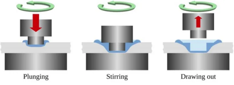
The process of building a small ship is usually done by welding sheets to a structure built of aluminium profiles due to their resistance to corrosion and high strength-to-density ratio. The AA6000 series are mostly used for both structural and sheet components. Spot arc welding is commonly used to fix the sheets and plates to the profiles. Metal Inert Gas (MIG) welding is used for the inner welds while Tungsten Inert Gas (TIG) welding is used for the external welds due to its better surface finish. These methods require highly qualified personnel and moving the welding equipment across long distances in places difficult to reach inside the shipbuilding facility. Arc welding involves using electricity in high currents, X-ray and UV radiation, toxic fumes and a high risk of injure to the workers. In addition to these drawbacks, arc welding usually leaves residual stress and distortions in the welded parts. The Friction Stir Spot Welding (FSSW) process does not involve the use of an electric arc to join the metal pieces, it does not produce fumes or harmful radiation, nor it requires highly qualified personnel. In addition, it leaves small residual stresses and a good surface termination [1, 2].Following these advances, the main goal of the present work is to study the FSSW welding parameters to obtain better quality welds, especially to study the role of the strain rate fields in the dwelling stage.
from the weld zone (drawing out). The shoulder minimises the occurrence of flaws and avoids the metal to spin out of the weld zone. During the dwelling time the materials from both plates are stirred up and the weld zone is expanded. In order to extend the limits of applicability for this welding process and to make it more reliable, a great amount of research is needed [4].
Figure 1: The three stages of Friction Stir Spot Welding.
Experimental modelling in FSSW is quite expensive and time consuming, given the numerous variables to be determined and the size of the test samples required. Due to the high temperature gradients in the welded parts, it is very difficult to measure their thermal history throughout the welding process. Numerical modelling is a known and very useful tool to aid the engineers in estimating the best tests to be carried out experimentally. It can be used to obtain a detailed estimation of thermo mechanical history so that microstructural changes can be well predicted. In the present work, the study of this process was done by numerical modelling and experimental testing and comparison between the results was done. Many authors have done reviews [4] and research [5] in this topic using diverse modelling techniques. The computational model approach used in this work is novel. It consists in using a two-dimensional mesh a with three-dimensional axisymmetric continuum model. This is explained further in section 2.3. The comparisons were done between the thermal and velocity fields from numerical modeling and the shape of the stirred zone in experimental results.
2. MATERIALS AND METHODS
The friction stir spot welding of two stacked AA6063 aluminium alloy round plates was done using a FSSW equipment and numerically simulated using the Finite Element Method [6].
The alloy composition is shown in Table 1. The pin and shoulder material was H13 steel alloy, and was modelled as analytical rigid for mechanical equations. The material parameters for both the plates and tool are shown in Table 2. The tool and plates dimensions for samples and modelling are shown in Table 3. Table 1: Alloy composition (%wt).[7]
Alloy Al Si Fe Mn Mg Cu Cr
AA6063 Base 0.2-0.6 0-0.35 0-0.1 0.45-0.9 0-0.1 0-0.1
Table 2: Material thermal parameters.[8]
MATERIAL PROPERTY STEEL TOOL ALUMINIUM PLATES
ρ [Kg/m 3 ] 7.8·103 2.7·103
Cp [J/Kg ºC] 0.5·103 1.05·103
k [W/m ºC] 40.0 207.0
Table 3: Tool and plates dimensions.
TOOL DIMENSION [mm] PLATES DIMENSION [mm]
Pin diameter 2.4 Plates thickness 1.2
Pin length 1.9 Plates radii (axial symmetry) 50
Experimental welding was done using circular plates of 50mm radius and a thickness of 1.2mm each. The shoulder and pin front surfaces were flat and smooth. The pin lateral surface was cylindrical and not threaded. The plates were welded at a rotating speed of 2000 rpm (209 rad/s). The backing plate was a two-inch thick mild steel plate. The plunging rate was about 6mm/min, while the dwelling stage was set at 5s.
2.1 Numerical modelling. Continuum mechanics equations.
The welding process under study is computationally costly, due to the high deformation rates, the temperature gradients and the highly non linear nature of the viscoplastic friction terms. This problem can be solved using a coupled thermo mechanical system of equations. Some simplifications were assumed: body forces and inertial forces were neglected; all gradients along the angular direction, θ, were assumed null. Therefore, all values of velocities, temperatures and pressure were constant respect to the angular dimension. Only the dwelling stage was modelled and temperature and velocity field results were obtained for every time step. Results at t=5s were chosen for discussion. The shoulder indentation in the upper plate was not considered for the present work.
The set of coupled equations can be written as:
; (1a)
(1b) In the system of equations above ρ is the material density, Cp is the heat capacity, k is the thermal
conductivity, T is the temperature and γ is the rate of heat generated by mechanical work. This term was
modelled as:
(2) Where the term enclosed in parentheses is the contraction (inner product) between the stress deviator
tensor and the strain rate tensor. The constant η is the fraction of mechanical work that is converted into heat (η=0.9) [5] . σ is the Cauchy stress tensor:
(3) In equation (3), p is the pressure,I is the identity tensor, and D, the strain velocity tensor, which was described by the symmetrical part of the velocity field gradient:
(4) Adopting the incompressibility hypothesis for representing the material behaviour, the stress deviator tensor can be related to the strain velocity tensor by the following expression:
(5) Using expressions (4) and (5) we can calculate the effective stress and strain rate tensors σe(the second invariant of Cauchy stress tensor σ)and the strain rate tensor εe:
(6)
(7) Using these definitions we can express an effective viscosity μ for the material (Perzyna’s relation):
0
=
·
σ
k
T
+
γ
·
=
Dt
DT
ρC
p
S
D
η·
=
γ
:
p
I
+
μD
=
σ
2
2
u
+
u
=
D
T
p
μD
=
S
2
(8) The rate of deformation was assumed as dependant on temperature and strain rate, taken into account
in the following expression for σe (Sellars and Tegart or Sheppard and Wright law) [10]:
; where (9)
Z is the Zener-Hollomon parameter, where Q is the activation energy, R is the universal constant of gases and T is the temperature in °K. Values for materials parameters constants n, A, Q and α. are shown in Table 4.
Table 4: Viscosity parameters[10]
MATERIAL A α [mm2N-1] n Q [J mol-1]
Aluminium alloy 0.224·1013 0.052 4.54 177876.4
2.3 Finite element modelling.
The continuum was modelled using an axisymmetrical mesh with a total of seven degrees of freedom per node: temperature, T, velocities in three dimensions, Vx, Vz, Vθ, node positions Ux, Uy, and pressure, P. This approach is considered novel, given that some authors used axial symmetry [11,12] but considered two dimensions in velocities, neglecting the importance of shear stresses due to the gradients of angular velocities in the other two coordinates, x and y.
The base plates were modelled using triangular elements with quadratic velocity interpolation and linear pressure interpolation, in order to have stability in pressure calculation in conjunction with null divergence in the velocity field. The quadratic interpolation of velocities allows the calculation of high stress gradients with better precision than with linear elements. The mesh used can be seen in Figure 2.
Figure 2: Two dimensional axisymmetric mesh. Full (top) and detail of the weld zone (bottom).
The boundary conditions regarding the thermal model were chosen as follows: A) heat loss due to convection and conduction, and B) completely adiabatic. For condition A, the heat flux was considered as normal convection type for free surfaces (top and perimeter surfaces) and contact diffusion type through the steel backing plate (boundary along x axis) and through the tool material. Heat loss through the backing plate was modelled as a Neumann type domain interface assuming a two inch thick backing steel plate in perfect
e eε
σ
=
μ
3
n
A
Z
α
=
σ
e1
sinh
1
1
RT
Q
ε
=
contact with the aluminium lower plate. The free end of the steel backing plate was considered at room temperature. Heat loss through the tool material was considered in the same manner.
The initial conditions were chosen at the end of the plunging stage but with a room temperature thermal field so that only the dwelling stage was modelled. This choice allowed the authors to estimate the heat generation of by the dwelling process alone. The heat generated has two sources: friction between tool and plates and internal friction due to plastic work. According to NANDANet.al. [9] only 5% of the total internal work is consumed in material change of shape and creation of dislocations and the rest is transformed into heat.
The mechanical boundary conditions were chosen as null vertical movement for the lower plate boundary (y=0 along x axis), symmetry around y axis (vertical axis at the left of the mesh in Fig 2). At the tool-material interface a prescribed tangential material velocity in coordinate θ was set (perpendicular to the mesh plane) as a linear function v = ω x, being x the radius. The angular speedω=209 rad/s in θ was chosen equal to the experimental tool spinning rate of 2000 rpm.
The algorithm of resolution involved two substeps: for the first substep, the velocity field was obtained assuming a constant temperature field, iterating to non-linearly adapt the values of viscosity associated to the local strain rates calculated in the previous iteration. Discrete equations were obtained from the classical Stokes problem for fully incompressible fluids and in concordance with the previously mentioned interpolations with an added Chorin type pseudo compressibility[13]. The linear system of equations for each iteration was solved by squared conjugate gradients using an incomplete LU factorisation pre-conditioner (SparseKit), as proposed by SAAD [14]. The temperature field was solved in the second substep using quadratic interpolation and a convection-diffusion problem, taking into account the heat generated by plastic flow using the velocity field calculated in the previous substep and a totally implicit solving scheme. The numerical solving method was the same as with the previous substep.
The time stepping scheme was implemented as totally implicit, used mainly as a pre-conditioner of the system of equations. Dwelling time was set equal to 5s. The problem was solved using a multiple purpose solver framework [15].
3. RESULTS
Numerical modelling for both conditions (A, with heat flow across the boundaries and B, adiabatic) was carried out and the results are shown (temperature and velocity fields) in Figures 3 to 6 below. Velocity fields in x and y coordinates resulted negligible, and therefore not shown.
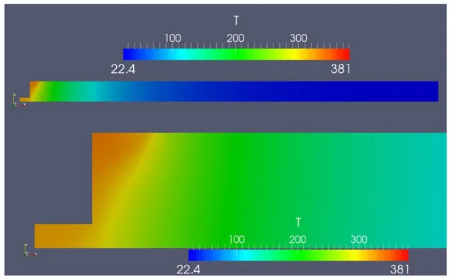
Figure 4: Temperature field at t=5s for the Stokes problem B without heat flux across the boundary, whole model (top) and weld zone (bottom). Temperatures are shown in degrees Celsius. Maximum temperature reached was 381ºC.
Figure 5: Velocity field in cm/s (perpendicular to the mesh surface) at t=5s for the Stokes problem A (with heat flux across the boundary), whole model (top) and weld zone (bottom).
Figure 6: Velocity field in cm/s(perpendicular to the mesh surface) at t=5s for the Stokes problem B (without heat flux across the boundary), whole model (top) and weld zone (bottom).
Figure 7: Longitudinal cut section of a test sample made of two stacked plates of1.2mm thickness welded using FSSW. The tool dimensions were the same as used in numerical modelling.
4. DISCUSSION
According to numerical modelling results, the resultant velocity fields were mainly tangential to concentric circles around the tool. The components of the velocity field in radial (x coordinate) and vertical (y coordinate) were negligible and therefore not shown. This can be due to the lack of grooves in the pin lateral surface and the flat shoulder surface used for the model. Future models should take into account these tool characteristics, most common in the industry. It is worth noticing that the heat input in the modelling was not due to friction in the tool-material interface since perfect adherence was set as boundary condition.
In D’URSO et. al.[6] authors used a two-dimensional model but did not consider material motion in circumferential direction or mixing of the welded material.
On the other hand, MA et.al. [16] did not consider the circumferential motion but added a set of boundary conditions called rotors by the authors to add vertical movement taking into account somewhat the effect of the pin thread.
material from the weld may have remained attached to the tool upon withdrawing, leaving rounded edges and a conical surface around the pin hole.
Figure 8: Superimposed images of numerical results (thermal field at t=5s for Stokes problem A) onto a longitudinal cut section of a test sample.
Figure 9: Superimposed images of numerical results (velocity field perpendicular to the mesh surface at t=5s for the Stokes problem A) onto a longitudinal cut section of a test sample.
zones shown in Figures 3, 4 and 8.It should be taken into account that the during the plunging stage the material is deformed and heated by friction and internal plastic work. This, in addition to the high temperatures at that spot, leads to a complete re-crystalisation of the material just underneath the pin front surface, as shown in Figure 7.
It seems that a perfect adherence between tool and base material is not a realistic condition, for it has to be taken into account the generation of heat by friction, previous to, and during the dwelling stage so that the calculated heat input can result in higher temperatures in the material. Future models should take this process into account by means of an interface friction model, for both the plunging and the dwelling stage, which introduces massive strains and material flow that cannot be predicted otherwise without that stage.
The constitutive equation used for the modelling was chosen for its material data availability in the range of strain rates and temperatures of FSSW. Nevertheless, it gives lower strain values than other constitutive equations, such as Johnson-Cook or Kocks and Meking laws, after KUYKENDALL[18]. This may have lead to lower values of internal heat due to friction, as seen in the temperature field results shown above.
4. CONCLUSIONS
Numerical modelling of the dwelling stage of the FSSW process was done using an axisymmetrical two-dimensional continuum. A novel approach using three-two-dimensional velocity fields and scalar temperature and pressure fields were used for the modelling. Two thermal boundary conditions were chosen: with heat loss to the surrounding media and adiabatic.
Experimental welding of aluminium sheets was done and samples from through-cut specimen were taken and compared to the modelling results.
The velocity fields showed the same shape as the experimental stirred zone, which means that the strain rate gradients are dominant in the process of friction stir spot welding through the internal heat generated by material viscous flow. The velocity and temperature fields results showed that the approach was successful despite a more accurate heat transfer boundary conditions have to be preset in future models to obtain more realistic results, taking into account the tool-plate friction into the heat input terms. This may lead to higher temperature values, even though the peak values found were close to those reported in literature. In addition, for future work it was found necessary to model the plunging stage since it generates initial thermo mechanical conditions for the dwelling stagethat cannot be obtained otherwise and end up in weld characteristics found in experimental specimens.
5. ACKNOWLEDGMENTS
Authors wish to thank CONICET for support given through grant PDTS201.
6. BIBLIOGRAPHY
[1] OLIVEIRA MIRANDA, A.C., GERLICH, A., WALBRIDGE, S., “Aluminum friction stir welds: Review of fatigue parameter data and probabilistic fracture mechanics analysis”, Engineering Fracture Mechanics,
n.147 pp. 243–260.2015.
[2] NANDAN, R., DEBROY, T., BHADESHIA, H.K.D.H., “Recent advances in friction-stir welding – pro-cess, weldment structure and properties”,Progress in Materials Science, n.53, pp. 980–1023, 2008.
[3] THOMAS, M.W., NICHOLAS, J., NEEDHAM, M.G., et al., “Friction Stir Butt welding”, GB Patent Application No.9125978.8 Dec 1991.
[4] HE, X., GU, F., BALL, A., “A review of numerical analysis of friction stir welding”, Progress in Materi-als Science, v. 65, pp. 1-66, 2014.
[5] NANDAN, R., ROY, G.G., LIENERT, T.J., “Numerical modelling of 3D plastic flow and heat transfer during friction stir welding of stainless steel”, Science and Technology of Welding and Joining, v.11 pp. 526– 37, 2006
[6] ZIENKIEWICZ, O.C., TAYLOR, R.L, The finite element method, McGraw Hill, v. I., v. II, 1991.
[9] NANDAN, R., ROY, G.G., DEBROY, T., “Numerical simulation of three-dimensional heat transfer and plastic flow during friction stir welding”, Metallurgical and MaterialsTransactionsA, v. 37A, pp. 1247-1259, 2006.
[10] SHEPPARD,T, WRIGHT, D.S., “Determination of Flow Stress. Part 1: Constitutive Equation for alu-minium alloys at elevated temperatures”, Metals Technology, pp 215, June 1979.
[11] D’URSO G, GIARDINI C. “FEM model for the thermo-mechanical characterization of friction stir spot welded joints”, International Journal of Material Forming, v.9, n.2, pp.149-160, 2015.
[12] MILES, M., KARKI, U.,HOVANSKI, Y. “Temperature and Material Flow Prediction in Friction-Stir Spot Welding of Advanced High-Strength Steel”, The Journal of The Minerals, Metals & Materials Society, v. 66, pp. 2130, 2014.
[13] CHORIN, A.J., “Numerical solution of the Navier-Stokes equations”, Mathematics of Computation, n. 42, pp. 745-762, 1968.
[14] SAAD, Y. “SPARSEKIT: a basic tool kit for sparse matrix computation (version 2)”, University of Illi-nois, Available at: http://www-users.cs.umn.edu/∼saad/software/SPARSKIT/, 1994 [as of April 1st, 2010]. [15] URQUIZA, S.A., VENERE, M. “An Application Framework Architecture for FEM and Other Related Solvers”, Mecánica Computacional, n 21, pp.3099-3109, Oct. 2002.
[16] MA, N., KUNUGI, A., HIRASHIMA, T., et al., “FEM simulation for friction spot joining process”,
Welding International, v. 23, n. 1, pp. 9-14, 2009.
[17] JEDRASIAK, P., SHERCLIFF, H.R., REILLY, A. “Thermal Modeling of Al-Al and Al-Steel Friction Stir Spot Welding”, Journal of Materials Engineering and Performance, pp. 4089-4098, 2016.