WOW - Wiki Aided Organization DraWing
MASTER DISSERTATIONRoberto Milton Gouveia Nunes
MASTER IN INFORMATICS ENGINEERINGSUPERVISOR
I
Acknowledgements
I would like to thank to the following:
1. Prof. Dr. David Aveiro. My supervisor, his critiques and guidance throughout the
elaboration of this thesis were extremely invaluable.
2. My colleagues Vítor Nóbrega and Duarte Pinto. The exchange of ideas has proven
to be most helpful in many aspects of this dissertation.
3. My family, friends and colleagues who have supported me in many ways through
this difficult journey. Special thanks to my father Arsénio Nunes, my mother
Susana Nunes and my sister Cláudia Nunes, and to my colleagues Aquilino
Viveiros and Artur Vieira who were always there since the beginning of this
II
Resumo
À medida que o mundo evolui, as organizações tornam-se progressivamente mais
complexas, e a necessidade de compreender essa complexidade aumenta de igual
forma. Com esta procura, surge a engenharia organizacional, que é uma área que
aparece com o intuito de tornar as organizações mais fáceis de compreender,
tentando-se colocar em prática o conceito de consciência organizacional, que significa que todos
os colaboradores que fazem parte de uma organização precisam de perceber como a
mesma funciona e qual o seu papel nela. A metodologia DEMO (Metodologia de
Engenharia de Design para Organizações) surgiu com o propósito de representar a
consciência organizacional, através da definição e criação de diagramas coerentes e
consistentes.
Wikis semânticos têm funcionalidades que podem ajudar na modelação de empresas. O
UEAOM (Modelo Adaptativo de Objetos Universal para Empresas) é um modelo que
permite a especificação e evolução dinâmica de linguagens, meta-modelos, modelos e
as suas representações na forma de diagramas e tabelas.
Neste projeto, foi implementado um Sistema baseado no UEAOM, e no Semantic Media
Wiki, que permite a criação e edição gráfica de diagramas. O UEAOM pode ser visto ao
nível do meta-modelo, onde uma linguagem é definida, e ao nível do modelo, onde
instâncias de classes desse modelo são criadas. O sistema desenvolvido por nós foca-se
ao nível do modelo, mas usa como base o projeto que se foca no meta-modelo.
A linguagem DEMO foi utilizada como exemplo para a implementação e testes de um
editor gráfico baseado nas tecnologias web e SVG, integrado com o Semantic Media Wiki
para permitir a edição de diagramas de organizações e navegação nos mesmos de uma
forma intuitiva, coerente e consistente.
Palavras-chave
III
Abstract
As the world evolves, organizations are becoming more and more complex, and the
need to understand that complexity is increasing as well. With this demand, arises
organizational engineering, which is a subject that emerged with the purpose to make
organizations easier to understand, by putting in practice the concept of organizational
self-awareness, which means that that the collaborators who are part of an
organization, need to understand it and know what their role in it is. The DEMO
methodology (Design Engineering Methodology for Organizations), came up with the
purpose of representing these organizations’ self-awareness, through the definition and creation of consistent and coherent diagrams.
Semantic wikis have features that can help in enterprise modelling. UEAOM (Universal
Enterprise Adaptive Organization Model) is a model that allows the specification and
dynamic evolution of languages, meta-models, models, and their representations as
diagrams and tables.
In this project, it was implemented a system based on UEAOM, and Semantic Media Wiki
which allows a graphical creation and edition of diagrams. UEAOM can be divided into
the meta-modeling level where a language is defined, and the modelling level where
instances of classes of that language are created. The system we developed focuses on
the modeling level, but will takes as a basis the project that focuses on meta-modeling.
The DEMO language was used as an example for the implementation and tests of a
graphical editor, based in web technologies and SVG, integrated with
SemanticMediaWiki to allow an intuitive, coherent and consistent navigation and
editing of organization diagrams.
Keywords
Organizational Engineering, UEAOM, SemanticMediaWiki, DEMO, SVG, Universal
IV
Contents Index
Acknowledgements ... I
Resumo ... II
Palavras-chave ... II
Abstract ... III
Keywords ... III
Contents Index ... IV
Figures Index ... VII
Tables Index ... VIII
1. Introduction ... 1
1.1. Motivation ... 2
1.2. Objectives ... 3
1.3. Content ... 4
2. Context ... 5
2.1. Enterprise Ontology Theoretical Concepts ... 5
2.2. World Ontology Specification Language (WOSL) ... 5
2.2.1. Factual Knowledge ... 5
2.3. Basic Ontological Notions... 11
2.4. Theoretical Foundations on Models ... 16
2.5. The Universal Enterprise Adaptive Object Model ... 17
2.5.1. Abstract Syntax ... 18
2.5.2. Concrete Syntax ... 22
3. State-of-the-art ... 26
3.1. Alternative Web-based Diagramming Solutions ... 26
3.1.1. Modelworld ... 26
3.1.2. Diagramo ... 27
3.1.3. RaphaelJS ... 28
3.1.4. JQuery SVG ... 29
3.1.5. SVG-Edit ... 30
3.1.6. Open Modeling ... 32
3.2. Choosing a diagramming web-technology ... 33
3.2.1. SVG ... 33
V
3.2.3. Canvas vs SVG Summary ... 34
3.2.4. Advantages ... 36
3.2.5. Disadvantages ... 36
3.2.6. Conclusion ... 37
4. Software and Programming Languages ... 38
4.1. MediaWiki ... 38
4.1.1. MediaWiki API (Application Programming Interface) ... 39
4.1.2. SemanticMediaWiki ... 39
4.1.3. SemanticForms Extension ... 41
4.1.4. SVG-Edit Extension ... 42
4.2. Scalable Vector Graphics (SVG) ... 43
4.2.1. Functionality ... 44
4.3. JavaScript ... 46
4.4. Jquery ... 47
4.4.1. JQuery’s Features ... 47
4.4.2. Ajax ... 48
5. DEMO Methodology on MediaWiki ... 50
5.1. Approach for creating wiki pages ... 51
5.2. Standard nomenclature for pages and properties ... 52
5.2.1. Semantic Forms ... 54
5.3. UEAOM implementation on SMW ... 55
5.3.1. Organization Artifacts (OAs) and Shapes ... 55
5.3.2. Organization Artifact Relations (OARs) and Connectors ... 60
5.3.3. Scopes of Interest, Diagrams, and Queries ... 63
5.3.4. Templates, Forms, and Properties ... 65
5.3.5. Implementation Overview ... 67
6. Universal Diagram Editor Implementation ... 70
6.1. SVG DOM Structure ... 71
6.2. Features ... 73
6.2.1. Create New Diagram ... 73
6.2.2. Create New Scope of Interest ... 75
6.2.3. Open Diagram ... 75
6.2.4. Delete Diagram ... 77
VI
6.2.6. Export Image ... 77
6.2.7. Create New Shape / Organization Artifact ... 77
6.2.8. Create New Connector / Organization Artifact Relation... 79
6.2.9. Select Symbol ... 80
6.2.10. Resize Shape ... 81
6.2.11. Move Shape ... 81
6.2.12. Edit Connector Points and Connector Moves ... 82
6.2.13. Edit Labels ... 82
6.2.14. Add/Remove Connector Moves ... 83
6.2.15. Bring to Front / Send to Back ... 83
6.3. Actions, Pages, and Properties Overview... 84
6.4. System Architecture ... 86
7. Conclusions ... 87
7.1. Technologies and Implementation ... 87
7.2. Future Work ... 88
7.2.1. Multiple Symbol Selection/Moving ... 88
7.2.2. Deletion of OAs and OARs ... 88
7.2.3. Connectors and OARs ... 89
8. References ... 90
9. Appendix ... 92
A.1 Installation manual ... 92
A.1.1 Testing the Installation: ... 95
A.2 UDE (Universal Diagram Editor) Code ... 96
A.2.1 HTML code (editor.html)... 96
VII
Figures Index
Figure 1 - UEAOM (simplified version) ... 1
Figure 2 - The meaning triangle ... 6
Figure 3 - The ontological parallelogram ... 7
Figure 4 - Statum type declarations ... 10
Figure 5 - Example of a reference law ... 10
Figure 6 - Example of a dependency law ... 10
Figure 7 - Example of a factum type ... 10
Figure 8 - The meaning triangle ... 12
Figure 9 - The ontological parallelogram ... 12
Figure 10 - Model triangle applied to organizations ... 12
Figure 11 - Meaning triangle applied to a transaction OA ... 12
Figure 12 - Model triangle applied to the organization space ... 12
Figure 13 - The model triangle ... 12
Figure 14 - Type Square ... 17
Figure 15 - Universal Enterprise Adaptive Object Model ... 20
Figure 16 - UEAOM - Abstract Syntax classes ... 21
Figure 17 - DEMO Ontological Meta-Model and UEAOM classes used to represent it ... 21
Figure 18 - UEAOM Concrete syntax ... 22
Figure 19 - DEMO concrete diagrams example and UEAOM classes used to represent them ... 24
Figure 20 - Modelword User Interface ... 26
Figure 21 - Modelworld Technical Architecture Layers ... 27
Figure 22 - Diagramo user interface ... 28
Figure 23 - SVG Load ... 29
Figure 24 - Jquery SVG Export ... 30
Figure 25 - SVG-Edit User Interface ... 30
Figure 26 - Performance comparison between SVG and canvas ... 35
Figure 27 - MediaWiki SVGEdit Extension ... 43
Figure 28 - SVG rectangle ... 45
Figure 29 - SVG polyline ... 46
Figure 30 - Universal Diagram Editor (UDE) ... 50
Figure 31 - DIAGRAM Template ... 54
Figure 32 - ELEMENTARY ACTOR ROLE V3.5 wiki page ... 56
Figure 33 - Oa 1 wiki page ... 56
Figure 34 - COMPOSITE ACTOR ROLE V3.5 Shape kind wiki page ... 57
Figure 35 - Shape 1 wiki page ... 57
Figure 36 - ELEMENTARY ACTOR ROLE V3.5 Shape kind component rect 0 ... 59
Figure 37 - Shape 1 component rect 0 ... 59
Figure 38 - TRANSACTION KIND.executed by.ELEMENTARY ACTOR ROLE wiki page ... 61
Figure 39 - Oar 1 wiki page ... 61
Figure 40 - EXECUTOR V3.5 wiki page ... 62
Figure 41 - Connector 1 wiki page ... 63
VIII
Figure 43 - Scopes of Interest wiki page ... 64
Figure 44 - Scope of interest 1 wiki page ... 64
Figure 45 - Create new OA page through form ... 65
Figure 46 - OA template ... 66
Figure 47 – OA form ... 66
Figure 48 - “Is part of diagram” property creation ... 67
Figure 49 - Part of the “Rent a car” ATD diagram ... 67
Figure 50 - Pages created by the meta-model editor ... 68
Figure 51 – Pages created by the UDE (Universal Diagram Editor) ... 69
Figure 52 - Universal Diagram Editor (UDE) ... 70
Figure 53 - “Rent a car” diagram SVG DOM structure ... 72
Figure 54 - Create New Diagram Dialog Form ... 74
Figure 55 - Create New Shape dialog form ... 78
Figure 56 - New OA form dialog ... 79
Figure 57 - Shape connector points ... 80
Figure 58 - Shape resizing... 81
Figure 59 - Edit Shape Labels ... 82
Figure 60 - Connector moves ... 83
Figure 61 – System Architecture ... 86
Figure 62 - Update process for the data in SMWAdmin ... 93
Tables Index
Table 1 - RaphaelJS example ... 29Table 2 - Canvas vs. SVG summary ... 34
Table 3 - Advantages of SVG and Canvas ... 36
Table 4 - Disadvantages of SVG and Canvas ... 37
Table 5 - SVG rectangle definition ... 45
Table 6 - SVG polyline definition ... 46
Table 7 – User-defined and auto-defined property values ... 85
1
1.
Introduction
This project focuses on the development of a web-based diagram editor, named as UDE
(Universal Diagram Editor). The initial purpose is to describe how organizations work,
and provide simplified views through different kinds of diagrams. This editor should also
allow the edition of any type of diagram in the future.
This project consists in the implementation of part of the UEAOM, which is a model that
systematizes the integrated management and adaptation of enterprise models, their
representations, their underlying meta-models (abstract syntax), and their
representation rules (concrete syntax) [1]. To accomplish this goal, we used SMW
(Semantic MediaWiki), which is the software used by the well-known Wikipedia, as a
basis. Each class of the UEAOM model corresponds to a wiki page or a wiki property on
SMW.
2
The UEAOM model was being improved at the same time this project was developed.
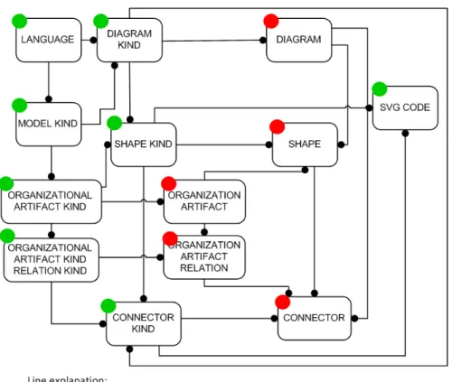
Figure 1, from [31], depicts a simplified version of UEAOM (full version can be found in
Figure 15).
It’s also important to say that this project, named as WOW (Wiki Organization draWing), was developed at the same time as the WAMM project (Wiki-Aided Meta Modeling)
[31]. WAMM was integrated in this project, and can be seen as a basis to WOW, because
it defines classes that will be used by the UDE, as we can view in Figure 1. The classes
marked with a red circle correspond to the classes which are created by the UDE, and
these depend on the classes that are created by the meta-model editor, marked with a
greed circle. As we can observe in the picture, the meta-model editor defines, for
instance, the diagram types, shape types, and connector types, and the UDE creates
instances of those classes, namely the diagrams, shapes, and connectors, etc, to use in
the UDE.
1.1.
Motivation
Nowadays, nearly 75% of the computer engineering projects fail to meet the user’s
expectations. One of the main causes is an insufficient or inadequate knowledge of the
organizational reality to be automated or supported by an information system. The
organizational engineering discipline emerged in the 90s and adds concepts and
engineering methods applied to organizations with the goal of understanding and
representing multiple facets of them, as well as make the analysis and organizational
changes easier, regardless of the implementation of the information systems. Semantic
wikis are easy to use for people with a low computer knowledge. We want it to be
possible that all the employees of a given organization are able to contribute to the
creation of a collective awareness of the organizational reality through the use of
semantic wikis. This tool enables a distributed and coherent collection of organizational
knowledge in the form of elements and semantic relations aligned with the
organizational reality, that allow the capture and monitoring of its evolution, as well as
3
1.2.
Objectives
Analysis of a MediaWiki and SemanticMediaWiki based prototype and extension of the prototype to allow visualization and incremental creation and edition of
organizational diagrams.
Development of a web-based diagram editor, and integration of the editor in SemanticMediaWiki, taking as a basis the existing editor on the Open Modeling
platform, the Modelword diagram editor and other existing solutions, and good
design practices implemented in these tools as well as on Microsoft Visio. The
technologies used were: JavaScript, AJAX and SVG for a maximum interactivity
and flexibility with the user interaction, with functionalities such as
auto-complete. This project extends an already existing extension that allows the
incremental edition of models based on textual descriptions, forms and semantic
web. Application and validation of the extension, using the “EU-Rent case” [23]
as an example. The theoretical and methodological basis to use in this project is
the DEMO (Design Engineering Methodology for Organizations) methodology,
promoted by Enterprise Engineering Institute with headquarters in the
4
1.3.
Content
In this sub-section, it is provided a brief description of the content of this document. In
chapter 2, «Context», there are some organizational engineering theoretical concepts
which are needed and are a good basis for the reader to understand further chapters.
Still in chapter 2 there is a description of the UEAOM, which is a model that systematizes
the integrated management and adaptation of enterprise models, their representations,
their underlying meta-models (abstract syntax), and their representation rules (concrete
syntax). In chapter 3, «State-of-the-art» it is describe the research that was done, where
we present some already existing web-based diagramming solutions and choose the
most adequate one to use in this project. In Chapter 4, «Software and programming
languages» we make an introduction and description of all the software and
programming languages that were used in this project. In chapter 5, «DEMO
Methodology on MediaWiki», we describe how the implementation of this project is
done on MediaWiki, i.e., definition of wiki pages, and how forms and templates are used.
In chapter 6, «Universal Diagram Editor Implementation», we describe some the
implementation of the UDE (Universal Diagram Editor), and all its features. Next we have
chapter 7, «Conclusion», and chapter 8, «References», and finally, on chapter 9 -
«Appendix», we have the installation manual of this project, and the HTML and
5
2.
Context
In this section we begin with an introduction to Organizational Engineering. We start
with some theoretical concepts, followed by a brief description of the Grammar of
WOSL, explained in the next sub-section. Then we proceed to the “Universal Enterprise Adaptive Object Model”, which is developed using this grammar. Both UEAOM and this project (which implements part of the UEAOM), were developed at the same time and
influenced one another.
2.1.
Enterprise Ontology Theoretical Concepts
A widely adopted definition of ontology is that an ontology is a formal, explicit
specification of a shared conceptualization. It regards the conceptualization of (a part
of) the world, so it is something in our mind. This conceptualization is supposed to be
shared, which is the practical goal of ontologies. This takes also place in communication.
Third, it is explicit. An ontology must be explicit and clear, there should be no room for
misunderstandings. Fourth, it is specified in a formal way. Natural language is
inappropriate for this task, because of its inherent ambiguity and impreciseness. The
notion of ontology as applied in this context is the notion of system ontology. Our goal
is to understand the essence of the construction and operation of complete systems,
more specifically, of enterprises. The goal of enterprise ontologies is to make available
the right amount of the right kind of knowledge of the operation of the company in a
manner that one is able to look through the distracting and confusing appearance of the
enterprise right into its deep kernel. [2]
2.2.
World Ontology Specification Language (WOSL)
2.2.1.
Factual Knowledge
2.2.1.1. The Ontological Parallelogram
Factual knowledge is the knowledge about the states and state changes of a world, like
knowing that a person, a car, or an insurance policy exists, as well as knowing that the
insurance policy of a car started at some date. The basis for understanding factual
6
signs as representations of objects in order to be able to communicate about these
objects in their absence.
Figure 2 - The meaning triangle
The elementary notions that we make use of, are designated by the words “sign”, “object” and “concept”. The notion of concept is considered to be a subjective notion, whereas sign and object are considered to be objective notions. Objective means that it
concerns things outside the human mind, and subjective means that it concerns things
that can only exist inside the human mind. The three notions are elaborated below.
A sign is an object that is used as a representation of something else. A well-known class of signs are the symbolic signs, as used in all natural languages. Examples of symbolic
signs are the person name "Ludwig Wittgenstein", or the car license number "16-EX-AF".
An object is an observable and identifiable individual thing, for example a person or a car. Only concrete objects are observable by human beings. However, there are many
interesting objects that are not observable. The number 3 for example or the composite
object denoted by "Ludwig Wittgenstein owns car 16-EX-AF". These objects are called
abstract objects. A concept is a subjective individual thing. It is a thought or mental picture of an object that a subject may have in his or her mind. Example of a concrete
concepts: the mental picture I have of the person Ludwig Wittgenstein. Examples of an
abstract concept: the fact that Ludwig Wittgenstein owns car 1 6-EX-AF.
The basic notions of sign, object and concept are related to each other by three basic notional relationships: designation, denotation, and reference. Designation is a relationship between a sign and a concept. We say that a sign designates a concept.
Example: The name "Ludwig Wittgenstein" designates a particular concept of the type
7
denotes an object. Examples: the name "Ludwig Wittgenstein" denotes the object
person Ludwig Wittgenstein. Reference is a relationship between a concept and an object: a concept refers to an object. Examples: the concept Ludwig Wittgenstein refers
to a particular person.
A class is a collection of objects. By definition a class contains all objects that conform to the associated type. Examples: the class of persons, i.e., the collection of objects that
share those properties that make them conform to the type person, the class of cars,
i.e., the collection of objects that conform to the type car, and the collection of object
pairs <person, car> that share the property that the person owns the car. Extension is a relationship between a type and a class. We say that a class is the extension of a type.
Examples: the class persons is the extension of the type person; the class cars is the
extension of the type car; the class ownerships is the extension of the type owns. The
relationships between individual concepts and generic concepts (types), and consequently between individual objects and classes are depicted in Figure 3. In this
figure, which is based on Figure 2, we have deliberately left out the signs (predicate
names and proper names) because they are not relevant in ontology. Ontology is about
the essence of things, not about how we name them. The resulting figure is called the
ontological parallelogram. It explains how (individual) concepts are created in the
human mind. The notional relationships instantiation, conformity, and population are
explained hereafter.
Figure 3 - The ontological parallelogram
Instantiation is a relationship between a concept and a type: every concept is an instantiation of a type. Examples: the person Ludwig Wittgenstein is an instantiation of
8
type. We say that an object conforms to a type. Examples: the object, denoted by the
sign "Ludwig Wittgenstein", conforms to the type person; the object, denoted by the
sign "16-EXAF", conforms to the type car. Population is a relationship between an object and a class. We say that a class is a population of objects. A more common way of
expressing this is saying that the object is a member of or belongs to the class. Example:
the object, denoted by the sign "Ludwig Wittgenstein", belongs to the class person. [12]
2.2.1.2. Stata and Facta
At any moment a world is in a particular state, which is simply defined as a set of objects.
These objects are said to be current during the time that the state prevails. A state
change is called a transition. The occurrence of a transition is called an event.
Consequently, a transition can take place several times during the lifetime of a world,
events however are unique. An event is caused by an act. In order to understand
profoundly what a state of a world is, and what a state transition is, it is necessary to
distinguish between two kinds of objects, which we will call stata (singular: statum) and
facta (singular: factum).
A statum is something that is just the case and that will always be the case; it is constant. Otherwise said, it is an inherent property of a thing or an inherent relationship between
things. Example: The author of book title T is A. The existence of these objects is
timeless. For example, a particular book title has a particular author. If it is the case at
some point in time, it will forever be the case. A derived statum is defined by its
derivation rule. The being specified of this rule is the only necessary and sufficient
condition for the existence of the derived statum. This marks an important difference
between a world and a database system about that world. E.g. the age of a person in
some world exists at any moment, however, it has to be computed when it is needed.
Stata are subject to existence laws. These laws require or prohibit the coexistence of
stata. For example, if the author of some book is “Ludwig Wittgenstein”, it cannot also be “John Irving”.
Contrary to a statum, a factum is the result or the effect of an act. Example: book title T has been published. The becoming existent of a factum is a transition. Before the
9
are subject to occurrence laws. These laws allow or prohibit sequences of transitions.
For example, sometime after the creation of the factum “loan L hasbeen started”, the transition “loan L has been ended” might occur, and in between several other facta may have been created, like “the fine for loan L has been paid”. [12]
2.2.1.3. World Ontology
We are now able to provide a precise definition of the ontology of a world: a world
ontology consists of the specification of the state space and the transition space of that
world. By the state space is understood the set of allowed or lawful states. It is specified
by means of the state base and the existence laws. The state base is the set of statum
types of which instances can exist in a state of the world. The existence laws determine
the inclusion or exclusion of the coexistence of stata. By the transition space is
understood the set of allowed or lawful sequences of transitions. It is specified by the
transition base and the occurrence laws. The transition base is the set of factum types
of which instances may occur in the world. Every such instance has a time stamp, which
is the event time. The occurrence laws determine the order in time in which facta are
allowed to occur. [2]
2.2.1.4. The Grammar of WOSL
WOSL is a language for the specification of the ontology of a world. In order to keep the
specification of the grammar of WOSL orderly and concise, we present it in a number of
figures, exhibited hereafter. Figure 4 exhibits the ways in which statum types can be
declared. By the declaration of a statum type is understood stating that the statum type
belongs to the state base of the world under consideration. Statum types can be
declared intensionally or extensionally. By intensional we mean the notation of the
statum type as a unary, binary, ternary etc. concept type. Intensional notations are
referred to be a bold small letter (or a string of small letters). Extensional notations are
referred to by a capital letter (or a string of capital letters). To understand what a state
of a world is, it is necessary to distinguish between two kinds of objects: stata and facta.
10
Figure 4 - Statum type declarations
Fig 1 and 2 show the specification of existence laws.
Figure 5 - Example of a reference law
Figure 6 - Example of a dependency law
Figure 7 shows an example of a factum type.
11
2.3.
Basic Ontological Notions
The ontological system definition was adopted from [24] which concerns the
construction and operation of a system. The corresponding type of model is the
white-box model, which is a direct conceptualization of the ontological system definition
presented next. Something is a system if and only if it has the following properties: (1) composition: a set of elements of some category (physical, biological, social, chemical
etc.); (2) environment: a set of elements of the same category, where the composition
and the environment are disjoint; (3) structure: a set of influencing bonds among the
elements in the composition and between these and the elements in the environment;
(4) production: the elements in the composition produce services that are delivered to
the elements in the environment. From [24] we find that in the Ψ-theory based DEMO
methodology, four aspect models of the complete ontological model of an organization
are distinguished. The Construction Model (CM) specifies the construction of the organization: the actor roles in the composition and the environment, as well as the
transaction kinds in which they are involved. The Process Model (PM) specifies the state space and the transition space of the coordination world. The State Model (SM) specifies the state space and the transition space of the production world. The Action Model (AM) consists of the action rules that serve as guidelines for the actor roles in the composition
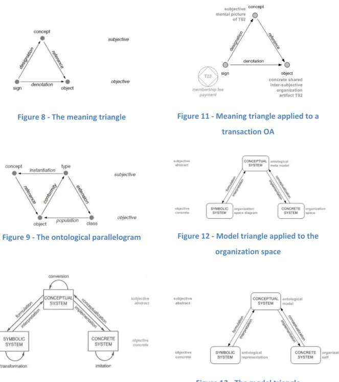
12 Figure 8 - The meaning triangle
Figure 9 - The ontological parallelogram
Figure 10 - Model triangle applied to
organizations
Figure 11 - Meaning triangle applied to a
transaction OA
Figure 12 - Model triangle applied to the
organization space
13
In Figure 8 and Figure 9, we find, respectively, the meaning triangle and the ontological
parallelogram, taken from [25], which explain how (individual) concepts are created in
the human mind. We will also base our claims in the model triangle, taken from [26] and
presented in Figure 13. We find that the model triangle coherently overlaps the meaning
triangle. This happens because a set of symbols – like a set of DEMO representations
(signs) that constitute a symbolic system – allow the interpretation of a set of concepts – like a set of DEMO aspect models, part of the ontological model, constituting a conceptual system. This conceptual system, in turn, consists in the conceptualization of
the “real” inter-subjective organizational self, i.e., the set of OAs constituting the concrete organization system's composition structure and production. Figure 10 depicts
an adaptation from the model triangle of Figure 13 and depicts our reasoning. We call
the set of all DEMO diagrams, tables and lists used to formulate the ontological model
as ontological representation.
Now relating with the meaning triangle, we can verify that a particular sign (e.g., a
transaction symbol with label membership fee payment), part of an ontological
representation (e.g., actor transaction diagram, representing a library's construction
model) designates (i.e., allows the interpretation or is the formulation) of the respective
concept of the particular transaction part of the respective ontological model (e.g.,
construction model). This subjective concept, in turn, refers to a concrete object of the
shared inter-subjective reality of the organization's human agents (e.g., the particular
OA transaction T02). Figure 11, an adaptation from the meaning triangle depicts this
other reasoning.
Another example of an OA related with T02 would be the transaction initiation OA,
relating T02 with actor role registrar (designated by A02), and formulated by a line
connecting the transaction and actor role symbols of T02 and A02. Actor role registrar
is, in turn, another OA of the construction space of the library. Once such role is
communicated to all employees of a library, it becomes a “living” abstract object part of the shared inter-subjective reality of the library's human agents. Such objects, along
with other OAs of the organizational inter-subjective reality, give human agents a way
to conceptualize their organizational responsibilities – in this case, requesting
14
living in the inter-subjective reality of an organization's members as the organizational
self.
From these notions we proposed a set of claims presented in more detail in [3] and
summarized next. An organization – besides producing a set of products or services for
its environment – also produces itself. That is, enclosed in its day-to-day operation, there
will be parts of its operation which change the organization system itself, i.e., change
the set of OAs that constitute its composition, structure and production. By formally and
explicitly specifying these change acts one keeps a definite and updated record of
produced OAs. Such a record – the OAs base – constitutes the means for one to always
be able to conceptualize the most current and updated ontological model of the
organizational self. Thus the continuous production of the organizational self should
include the synchronized production of the collective and subjective “picture” (awareness) of the organizational self – the conceptualization that constitutes its
ontological model – thanks to the synchronized production of the respective symbolic
system – an ontological representation that allows the interpretation of the ontological
model and the conceptualization (awareness) of the organizational self. To separate
concerns, we propose that change acts are performed by a (sub) organization
considered to exist in every organization (O) that we call: G.O.D. Organization (GO) –
change acts lead to the Generation, Operationalization and Discontinuation of OAs. The
GO's production world will contain the current state of O's self as well as its relevant
state change history.
The UDE (Universal Diagram Editor) that was developed in this project is to be used by
the GO of each organization, and other employees other than the ones who belong to
the GO, should be able to view the diagrams, in order to be aware of the organizational
self.
The GO has the role of continuously realizing and capturing changes of organizational
reality. Thus, by implementing the GO pattern in a real organization, in an appropriate
manner, providing automatic generation of ontological representations derived from
the OAs base, one can achieve OSA. This is possible because one can implement clear
15
produce the appropriate ontological representation which, in turn, allows the
appropriate interpretation of the ontological model, that is, the correct
conceptualization of the organizational self.
OAs constituting the organizational self are arranged in a certain manner as to specify
all the spaces (state, process, action and structure) of an organization's world, i.e., they
have to obey certain rules of arrangement between them. We call the specification of
these rules as the ontological Meta model. The ontological meta-model is the
conceptualization of the OA space. By OA space we understand the set of allowed OAs.
It is specified by the OA base and OA laws. The OA base is the set of OA kinds of which
instances, called OAs, may occur in the state base of the GO's world. The OA laws
determine the inclusion or exclusion of the coexistence of OAs. The definition of the OA
space is quite similar to the definition of state space of an organization's production
world – specified in World Ontology Specification Language (WOSL) [12] – and, thus, it
is appropriate to use WOSL to express the ontological meta-model in, what we propose
to call: the Organization Space Diagram (OSD). DEMO's OSD is currently called as the
DEMO Meta Model (DMM), the chosen name for the specification provided in [27] and
consisting, in practice, in the OSDs corresponding to the four DEMO aspect models: SM,
CM, PM and AM. These diagrams formulate, for each aspect model, the OA kinds out of
which instances – OAs – can occur in the organizational self and coexistence rules
governing how to arrange these instances. Another reason we propose to use the
expression Organization Space Diagram is because we're in fact looking at a Space
Diagram which, following the model triangle [26], is a symbolic system which is a
formulation of the conceptual system of the ontological meta model. So, for coherency
reasons, one should not use terms “Meta” and “Model” to name those figures but use, instead, the term Organization Space Diagram. The OSD allows the interpretation, in
one's mind, of the ontological meta-model. The complete set of organization artifact
kinds and laws governing the arrangement of their instances constitutes the
organization space. The conceptualization of the organization space consists in the
ontological meta-model which, in turn, is formulated in what we call the Organization
Space Diagram. A depiction of this reasoning is present in Figure 12, another adaptation
16
evolution of the conceptual model proposed in other works, taking in account
state-of-the-art related model theory and concepts described next.
2.4.
Theoretical Foundations on Models
In a graphical modeling language, the vocabulary is expressed in terms of pictorial signs.
Those graphical primitives form the concrete syntax i.e. the lexical layer of such
language. The abstract syntax, on the other hand, is usually defined in terms of an
abstract visual graph or a meta-model specification. A meta-model specification of a
language defines the set of grammatically correct models that can be constructed using
that language, a vocabulary. The concrete syntax provides a concrete representational
system for expressing the elements of that meta-model. In a communication process,
besides agreeing on a common vocabulary, the participants need to also share the
meaning for the syntactical constructs being communicated so they are able to interpret
in a compatible manner the expressions being used. To this end a language's semantics
can be constructed in two parts: a semantic domain i.e. the real world entities to which
those semantics apply and a semantic mapping from the syntactic vocabulary to such
domain that tells us the meaning of each of the language's expressions as an element in
that specific domain. In graphical languages, vocabulary, syntax and semantics cannot
be clearly separable. A graphical vocabulary of a modeling language may include shapes
of differing sizes and colors that often fall into a hierarchical typing that constrains the
syntax and informs about the semantics of the system. The abstract syntax of a model
manages the formal structure of the model elements and the relationships amongst
them.
The MetaObject Facility (MOF) Specification is the industry-standard environment
where models can be exported from one application, imported into another,
transported across a network, stored in a repository and then retrieved, rendered into
different formats like XMI or XML, transformed, and used to generate application code.
The Adaptive Object Model (AOM) is a pattern that represents classes, attributes, and
relationships as meta-data. It is a model based on instances rather than classes. Users
change the meta-data (object model) to reflect changes in the domain. These changes
17
and interprets it. Consequently, the object model is active, when you change it; the
system changes immediately. [4]
2.5.
The Universal Enterprise Adaptive Object Model
Figure 14 - Type Square
The long term objective of our research is the development of a wiki-based system that
allows an effective integrated enterprise modeling, while allowing dynamic evolution of
meta-models, models and their representations, while providing intuitive navigation
through their elements and also their semantics, allowing wide-spread model
interpretation and distributed model creation and change, reflecting enterprise
changes, thus addressing our problem. An essential step in this direction is what we call
the Universal Enterprise Adaptive Object Model (UEAOM), depicted in Figure 15. We
apply the AOM pattern referred in the previous section so that each page or semantic
property of our semantic wiki-based system corresponds to instances of classes of our
AOM.
Wiki pages, that are instances of class DIAGRAM, automatically generate SVG diagrams
based on shape and connector pages that are part of the corresponding diagram. These
wiki pages also allow dynamic editing of diagrams and underlying models. We also apply
the type-square pattern – depicted in Figure 14– 4 times as to allow run-time dynamic
change of: (1) meta-model elements, (2) model elements, (3) shape elements and (4)
connector elements. The UEAOM is represented with the World Ontology Specification
Language (WOSL). WOSL is based in Object Role Modeling language which is also used
as a base for the specification of the anatomy of Archimate, a similar effort to ours.In
[29], a relation between Adaptive Object Model pattern and the MOF standard is
18
M0 and knowledge level; classes, attributes, relations and behavior is equivalent to M1,
being M2 an equivalent to the models used to define an AOM. As in the [29], in our
UEAOM all these MOF levels are projected as run-time instances. In our prototype
system, we have as instances both organization artifacts – i.e., concrete organization
models – and organization artifact kinds – i.e., the meta-model specification or, in other
words, the abstract syntax. So both M1 and M2 levels of the MOF framework exist and
change at run-time. But the MOF and the initiative in [29] are too software development
oriented and too complex for our needs.The main idea is to apply these fundamental
theoretical foundations and adapt them to the field of enterprise ontology.
Having the UEAOM contextualized, an explanation of its content is now due. With the
UEAOM's classes we are not explicitly specifying syntaxes of particular modeling
languages. What we can do, while instantiating these classes, is to specify any syntax of
any modeling language, along with particular models of each language, and also their
evolution, all this in run-time. This is why we named our editor UDE (Universal Diagram
Editor), which means it can create and edit any kind of diagram. For a better
understanding and following the essential and important validation by instantiation
principle [27] we present, for all elements of our AOM, example instances for the DEMO
language, namely a fragment of the EU-rent case's Construction Model and its
respective Actor Transaction Diagram. Thus, we can find, in red color expressions,
instances of both our classes and fact types of our UEAOM concerning the EU-rent case
which allow a better interpretation of this proposal.
2.5.1.
Abstract Syntax
Relevant classes for the specification of the abstract syntax of any version of any
language are presented in Figure 16. The main concepts of the abstract syntax
specification are expressed in the classes LANGUAGE, MODEL KIND, ORGANIZATIONAL
ARTIFACT KIND (OAK) and ORGANIZATIONAL ARTIFACT RELATION KIND (OAKRK). They
specify all allowed artifacts (e.g. transaction kind OAK and transaction execution relation
OAKRK) for different types of models that can exist for different languages. Class
ORGANIZATIONAL ARTIFACT RELATION KIND has ten properties that can be divided in
two groups of five where each group specifies one of the two sides of an allowed relation
19
can be done around the names of the two OAKs being related. Most times, only the infix
needs to be specified. With the unicity and dependency properties we specify the
cardinality of the relation and which OAKs are mandatory or not to participate in the
relation. Reference law fact types specify which two OAKs are allowed to participate in
this relation. Practical example of the first set of the referred 5 properties: F Transaction
Kind T is initiated by Elementary Actor Role corresponds to a set of Dependency 1,
Reference law 1, Unicity 1, Infix_1_2 and Reference law 2. F Elementary Actor Role T is
initiator ofTransaction Kind would be its corresponding Dependency 2, Reference law
2, Unicity 2, Infix_2_1 and Reference law 1. Thanks to this part of our UEAOM
specification we allow a precise and formal formulation of the abstract syntax of models,
already giving considerable semantics thanks to the prefix, infix, suffix and OAK names
that can be composed in formulations for each direction of the relation. Instances of
class ORGANIZATION ARTIFACT PROPERTY specify intrinsic properties of OAKs, like
identifiers and names. The respective property DOMAIN allows us to specify the domain
for each intrinsic property of an OAK (e.g., string, number, etc.). Examples of instances
are property transaction id with domain T<number> or transaction name with domain
20
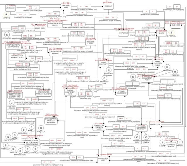
Figure 15 - Universal Enterprise Adaptive Object Model
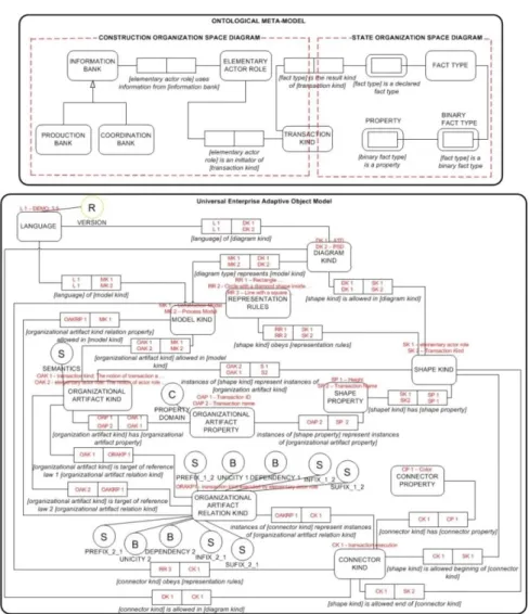
In Figure 17we can see an excerpt of the current DEMO ontological meta-model and
the UEAOM classes used to define it. Both these models are the equivalent to the M2
MOF model that, as we have seen, sets the rules for specifying concrete models. All
elements of this meta-model can be considered instances of the classes we just have
presented. The binary fact type [elementary actor role] is an initiator of [transaction
kind] is, in our UEAOM, an instance of ORGANIZATIONAL ARTIFACT RELATION KIND class,
with values for the infixes being: initiates and initiated by. There are, however, other
classes: DIAGRAM KIND, SHAPE KIND, CONNECTOR KIND, CONNECTOR and SHAPE
PROPERTY that are present in this Figure 17and are part of the meta-model level of the
UEAOM but are not part of the abstract syntax, these will be explained in more detail in
21
Figure 16 - UEAOM - Abstract Syntax classes
22
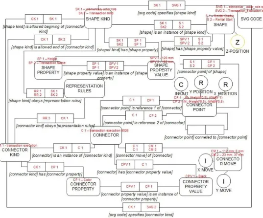
Figure 18 - UEAOM Concrete syntax
2.5.2.
Concrete Syntax
The UEAOM classes that allow the specification of rules for the concrete representation
of models, i.e., the concrete syntax, are presented next. These classes, together with all
their inter-relating fact types are present in Figure 18. With the class SHAPE KIND,
instances of the types of shapes allowed to be part of diagram kinds representing certain
model kinds are specified. These shape kinds are also specifically connected to the OAKs
whose instances they will represent. For example, the elementary actor role shape is
allowed in diagram kind Actor Transaction Diagram, which represents the construction
model of DEMO language. Instances of this shape represent instances of OAK actor role.
With SHAPE PROPERTY, we specify the properties for each shape, e.g., line color and
actor id label of actor role shape. Instances of CONNECTOR KIND specify allowed
representations for OAKRs, e.g. transaction initiation connector instances represent
instances of OAKR transaction initiation. With CONNECTOR PROPERTY, the properties of
each connector are specified, e.g., for the just mentioned connector, line color: black
23
Instances of REPRESENTATION RULES class, are an informal textual based specification
of rules on how ORGANIZATIONAL ARTIFACT KINDS and ORGANIZATIONAL ARTIFACT
RELATION KINDS should be represented. These rules are taken in consideration in either
SHAPES or CONNECTORS that represent those OAKs and OAKRKs. For example, a
transaction is a black circle with a black diamond inside. It is also according to the
REPRESENTATION RULES that we have a definite answer if an OAKRK will give origin or
not to a connector or if instead it will be represented by the connection of two shape
kinds directly. Revisiting the full example from Figure 2 - The meaning triangle, an
elementary actor role shape would be an instance of class SHAPE KIND, for the
representation of instances of the actor role OAK. Transaction shape would also be an
instance of SHAPE KIND for the representation of instances of transaction OAK. So an
instance of class CONNECTOR KIND for the representation of this OAKR would be
transaction initiator connector, with properties like line type: dashed. Many of the
SHAPE KINDs and CONNECTOR KINDs are comprised by multiple symbols that need to
be considered individually as having a set of properties. Although in most cases the
aggregate of composing symbols are treated as “one” in the diagram drafting, such as a circle and diamond in an actor transaction diagram transaction, that have a fixed size
(height and width) and none of them can be altered, there are also cases in which
symbols need to be treated and moved in the diagrams in a separate and independent
way having their own set of SHAPE PROPERTIES or CONNECTOR PROPERTIES like, for
example, in a process step diagram where the diamond inside the transaction can be
moved and re-sized according to the needs. As a solution for this, we have classes
SYMBOL ELEMENT KIND that specify each symbol element to be present in a shape kind
or connector kind and SYMBOL ELEMENT that are instances of SYMBOL ELEMENT KIND
and specify concrete representations of SYMBOL ELEMENTS of a specific kind. As an
example of this we can consider the actor transaction diagram SHAPE KIND transaction
as being composed by the SYMBOL ELEMENT KINDS Transaction Diamond and
Transaction Circle.
24
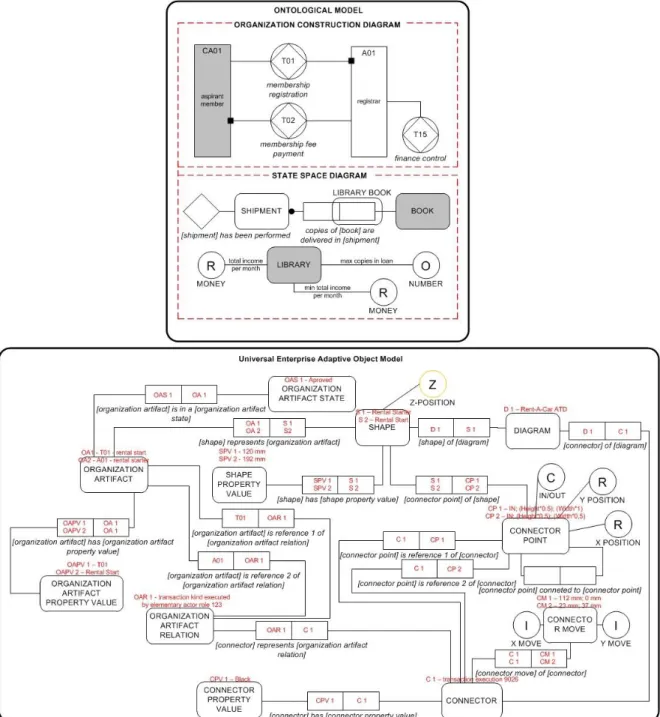
Figure 19 - DEMO concrete diagrams example and UEAOM classes used to represent them
In Figure 19 we have a partial example of a concrete representation of the DEMO
ontological models of an Actor Transaction Diagram and Object Fact Diagram and the
corresponding part in the UEAOM. DEMO Ontological models are the equivalent to the
M1 level of MOF and instances of their OA's to the MOF's M0 level.
Ontological Models and their representation are covered in the UEAOM by the classes:
DIAGRAM, where concrete instances of a certain DIAGRAM KIND are specified; SHAPE,
25
concrete instances of SHAPE PROPERTY are specified; CONNECTOR, where concrete
instances of CONNECTOR KIND are specified; CONNECTOR PROPERTY VALUE, where
concrete properties of the CONNECTOR PROPERTY are specified; ORGANIZATIONAL
ARTIFACT, where concrete instances of ORGANIZATIONAL ARTIFACT KIND are specified;
ORGANIZATIONAL ARTIFACT PROPERTY VALUE, where concrete OA properties are
specified and ORGANIZATIONAL ARTIFACT RELATION, where concrete instances of
ORGANIZATIONAL ARTIFACT RELATION KIND are specified and all their relating fact
types. In this way, also allowing them to be changed in an easy and consistent way in
run-time environment.
Again using a concrete example from Figure 19, we have the “CA-01 aspirant member shape”, this is an instance of SHAPE (this SHAPE an instance itself of the SHAPE KIND “Composite Actor Role”) that represents the ORGANIZATIONAL ARTIFACT “CA-01 aspirant member” (itself an instance of the ORGANIZATIONAL ARTIFACT KIND “Composite Actor Role”); the string “aspirant member” is an instance of SHAPE PROPERTY VALUE (that represents the instance of ORGANIZATIONAL ARTIFACT
PROPERTY VALUE “aspirant member”) and so is “CA-01”. These two strings are VALUES, instances of the SHAPE PROPERTIES “Actor Name” and “Actor ID” respectively (that again represent the instances of ORGANIZATIONAL ARTIFACT PROPERTY VALUE
“Composite Actor Name” and “Composite Actor ID”).
The DIAGRAM KIND and MODEL KIND classes were not present in the original DEMO
Ontological meta-model as all models were specified in this single meta-model. But in
the UEAOM, as we have generalized this definition to accommodate any language for
organizational modeling, the DIAGRAM KIND and MODEL KIND classes are vital so we
can relate to each specific Ontological Model. Actor Transaction Diagram or Process Step
Diagram would be examples of instances of this DIAGRAM KIND while the first would be
a representation of the MODEL KIND Construction Model and the second a
representation of the MODEL KIND Process Model. The LANGUAGE class and its property
VERSION is used to define the modeling language being modeled and the version of such
26
3.
State-of-the-art
3.1.
Alternative Web-based Diagramming Solutions
In this chapter we make a review of some already existing solutions of web-based
diagram editors. We will see how those editors load shapes, how they save information
about shapes while working on the editor, and how they export information about
shapes when saving the diagram.
3.1.1.
Modelworld
Modelworld is an online diagramming tool that runs in a browser, does not require
installation or plugins. Users can access the diagrams anywhere. It also allows multi-user
access. It has specific support for the following languages: DEMO, Archimate, BPMN,
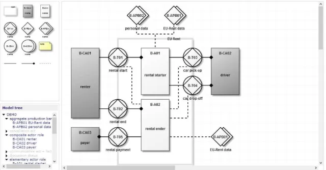
IDEF and UML. Figure 20 illustrates modelworld user interface.
Figure 20 - Modelword User Interface
Modelword uses HTML5 canvas with JavaScript, and it also uses Ajax for asynchronous
requests to the server, by the client’s machine. The server uses PHP and MySQL.
Information about shapes is kept in a MySQL database. Every time the user creates,
edits, or deletes a shape, a request is made to the database, and the corresponding
database tables of that shape are edited. For internet explorer 7 and 8, that do not
support HTML5, it is used JavaScript emulation of HTML5. Figure 21 illustrates
27
Figure 21 - Modelworld Technical Architecture Layers
When a user wants to open a diagram, an Ajax request is sent to the server, php on the
server generates the code to draw the diagram, that code is sent back to the client and
executed on the client’s machine through the JavaScript eval function, and the diagram is generated. The generated JavaScript code includes functions like “drawIcon” and “drawLine”.
A simple example that involves modifying data, would be adding a new shape. To create
a new shape, an Ajax request is made from the client machine. Then a php script handles
that request by calling a function to create the shape and insert it on the database. Then
a query is made to the database to request that shape’s properties, and a php function generates the code to create the shape. That code is sent back to the client and executed
through the JavaScript eval function. This also helps reducing the server load. [18]
3.1.2.
Diagramo
Diagramo is an online diagramming tool implemented with pure HTML5 and JavaScript.
No flash java or other plugins. It allow collaborative diagram editing. Diagrams can be
exported in three different formats – SVG, GIF and JPEG. It is an open source project.
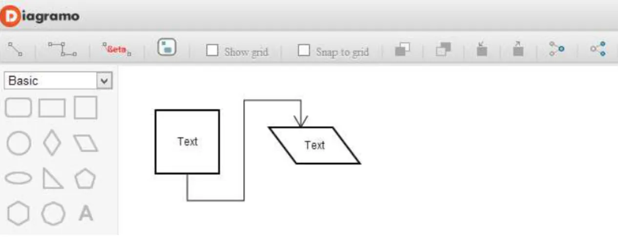
28
Figure 22 - Diagramo user interface
It has support for basic shapes like rectangles, circles and polygons. It also has a smart
connection handler that automatically adjust when the shapes are being moved. Manual
editing of the connector line is also supported. Good support for labels, and group
selection. It also allows the grouping of symbols. However, this editor’s project has too many files and lines of code, for such a simple editor, and the architecture is difficult to
understand, at least without having an arquitecture model. It’s a good editor, but only for basic shapes. It would be difficult to add more elaborate and complex shapes to the
palette with this kind of architecture.
3.1.3.
RaphaelJS
RaphaelJS is a small JavaScript library that simplifies work with vector graphics on the
web. It has features such has image crop and rotate, or specific chart creation that can
be easily achieved through the library API.
RaphaelJS uses the SVG W3C Recommendation and VML (vector markup language) as a
base for creating graphics. This means that every graphical object that is created is also
a DOM object. These objects can be modified later and it is also possible to add event
handlers. RaphaelJS’s goal is to provide an adapter that makes drawing vector art cross -browser compatible and easy. RaphaelJS support the following web -browsers: Firefox
3.0+, Safari 3.0+, Chrome 5.0+, Opera 9.5+ and Internet Explorer 6.0+. In Table 1 it is
possible to see how to create a canvas, add a circle to it, and modify its color and
stroke-color. The code is simple and intuitive.
29
// Creates circle at x = 50, y = 40, with radius 10 var circle = paper.circle(50, 40, 10);
// Sets the fill attribute of the circle to red (#f00)
circle.attr("fill", "#f00");
// Sets the stroke attribute of the circle to white
circle.attr("stroke", "#fff");
Table 1 - RaphaelJS example
RaphaelJS is a very good library, but we consider it more driven to animations and it still
lacks in interactivity, which is what we are trying to achieve. Interactivity is supported,
but when trying to create more elaborate examples, the code can be very complex and
difficult to understand. [19]
3.1.4.
JQuery SVG
JQuery SVG is a JQuery plugin, which allows interaction with an SVG canvas. JQuery itself
was initially developed for HTML, and not SVG, although most of the methods work with
SVG. JQuery SVG library helps overcoming these problems, such as enabling SVG
element selection through its class, just like in HTML. JQuery SVG has some useful
functions to work with SVG, such as loading SVG content from an external file to the
canvas. Figure 23 illustrates an example.
Figure 23 - SVG Load
When the user clicks the button to which the event has been added, the SVG code that
is in a certain location, will be loaded to a div, in the case the div with the id “svgload”. This is useful if a shape has to be defined and saved on a file on the server. We can easily
“import” that shape to the canvas.
JQuery SVG has also exporting features that allow an SVG element to be exported to a
30
Figure 24 - Jquery SVG Export
Through this function, by clicking on a button, the SVG code that is on a certain div, in
this case, “#svgbasis”, can be sent to another div, “#svgexport”. This function could be modified to save the SVG element as a file in a desired location.
In this project, we did not use JQuery SVG, because JQuery itself evolved since the last
released version of JQuery SVG, and though JQuery isn’t yet fully compatible with SVG,
most of the functions and methods work, and for the tasks we wanted to implement,
JQuery alone did the job.
3.1.5.
SVG-Edit
SVG-edit is a web-based, open source graphical editor based on SVG and JavaScript. It
does not require an installation, only a compatible browser. It runs on the client side. It
has browser support for Firefox 1.5+, Opera 9.5+, Safari 4+, Chrome 1+, and Internet
Explorer 6+ (with the Chrome Frame plugin). Figure 25 illustrates SVG-edit user
interface, with some basic shapes drawn.
31 3.1.5.1. Components
SVG-edit consists of two major components: svg-editor.js and svgcanvas.js. These
components work cooperatively. File svgcanvas.js can be used outside SVG-edit,
allowing developers to create alternative interfaces to the canvas. The term canvas is
not to be confused with HTML5 canvas element. In SVG-edit, canvas simply refers to a
drawing area.
3.1.5.2. Main Features Free-hand drawing Lines and Polylines Rectangles and Squares Ellipses and Circles Polygons/Curved paths Stylable Text
Raster Images
Select/move/resize/rotate
Undo/Redo
Color/Gradient picker Grouping/Ungrouping Shape Aligning
Zoom
Import SVG into Drawing Connector lines and Arrows Export Image to PNG
SVG-edit is a very good graphical editor, intuitive, and has many useful features like the
ones described before, with good primitives for drawing basic shapes, and also
composite and more elaborate shapes. However, SVG-edit is not focused on
diagramming, it is more focused in general image drawing. Its support for connectors is
still very poor at the moment, as it only allows to draw straight line connectors, and
connector points are not implemented. In Figure 25 there is an example of a connector,
32
the selection boundary, and not to the circle boundary. But this editor is an interesting
solution and has a good margin of progression. [21]
3.1.6.
Open Modeling
3.1.6.1. Description
Open modeling is a web-based application to model and publish architecture models,
procedures and related structured information. Not only publishing is done on the web,
but modeling and maintaining the information (texts and diagrams) is done using the
well-known web browser. The modelers of this information can see exactly the same
(WYSIWYG) result asthose who view the information. Open modeling supports DEMO
methodology, Archimate, and other modeling languages.
3.1.6.2. Open Modeling Installation Software
The open modeling editor works under a server which requires the following software:
Apache Tomcat– an open-source software implementation of the Java Servlet and JavaServer Pages technologies. The Java Servlet and JavaServer Pages
specifications are developed under the Java Community Process.
Java Development Kit– an Oracle Corporation product aimed Java developers. It is composed by a compiler and libraries.
MySQL Essential– Referred to as Structured Query Language is a programming language designed for managing data in relational database management
systems (RDBMS). Is scope includes data insert, query, update and delete,
schema creation and modification, and data access control.
3.1.6.3. Usage Scenarios
An example scenario of the use of Open Modeling: a department maintains an
organization chart. This department has the authorization to modify this chart. The
department “Process Management” uses the department names in the procedure
descriptions. The tasks of the department and the functionaries are maintained by the
department “Human Resources”. Users who don't work for Human Resource can view
33
Another example is the maintenance of business objectives. The management team
connects the business objectives to business processes. Some users will be allowed to
view the objectives, others may not. This usage is easy to implement with Open
Modeling. [22]
3.1.6.4. Conclusion
Open modeling tool is a good starting point for creating a web-based diagram editor,
taking as a basis the DEMO Methodology, but there are several changes that would have
to be made. The database of the open modeling tool is redundant and highly complex
with hundreds of tables, and the interface for manipulating the diagrams is not properly
user-friendly, since too many clicks have to be made to achieve a certain task, for
instance, to create a connector between two elements, the user had to click on one of
them, hold shift, and click on the other. Then has to right click on the selected elements,
and choose the option “create connector between shapes”. This kind of user interface
can still be improved to be more similar intuitive and simple, like clicking on the
connector kind, then clicking on the first shape, hold and drag mouse to the second
shape, and release the mouse.
3.2.
Choosing a diagramming web-technology
During our research and based on the alternative editors we reviewed, we decided that
the best solution was to build a web-based diagram editor from scratch, and that there
were two main web-technologies that were the most adequate for this kind of project
– SVG and HTML5 canvas. In this section, we will provide a comparison between both, state the advantages and disadvantages of both, choose most adequate technology for
this project, and support that choice.
3.2.1.
SVG
SVG is used to describe Scalable Vector Graphics, is based on XML, and can be easily
integrated with HTML. It is built into the document using elements, attributes, and
styles. SVG content can be static, dynamic, interactive and animated — it is very flexible.
It can also be styled with CSS and add dynamic behavior to it using the SVG DOM. And