Brazilian Journal of Physics, vol. 39, no. 3, September, 2009 519
Study on Dual-Concentric-Core Dispersion Compensation Photonic Crystal Fiber
Zhao-yuan Song∗
Key Laboratory of Metastable Material Science & Technology, Yanshan University, Qinhuangdao 066004, China Institute of Infrared Optical Fibers and Sensors, Yanshan University, Qinhuangdao 066004, China and
College of Science, Liaoning University of Petroleum & Chemical Technology, Fushun 113001, China Lan-tian Hou
Key Laboratory of Metastable Material Science & Technology, Yanshan University, Qinhuangdao 066004, China and
Institute of Infrared Optical Fibers and Sensors, Yanshan University, Qinhuangdao 066004, China Xing-tao Zhao, Dong-bin Wei, Xiao-dong Liu, and Zhao-lun Liu
Institute of Infrared Optical Fibers and Sensors, Yanshan University, Qinhuangdao 066004, China (Received on 23 April, 2008)
The dual-concentric-core photonic crystal fiber composed of pure silica and air is proposed in this paper. Around 1.55µm, it exhibits a negative chromatic dispersion as high as -5850 ps/km/nm. Based on multipole method, a systemic and in-depth simulation is realized to investigate the mode characteristics. The explanations to propagation states of the fundamental mode and the second mode are given elaborately. Finally, the variation of structural parameters is investigated to evaluate the tolerance of the fabrication. As a result, the designed fiber can be fabricated easily.
Keywords: Dual-concentric-core photonic crystal fiber; Dispersion compensation; Multipole method
I. INTRODUCTION
Chromatic dispersion is one of the most fundamental char-acteristics of optical fiber. The pulse is broadened mostly because of this factor. At present, millions of kilometers of installed optical links around the world operate with 1.31µm optimized G.652 type of single-mode fibers. Due to the availability of the erbium-doped fiber amplifiers (EDFA) and also because of lower loss at the 1.55µm band, there has been a substantial interest to operate these installed fibers at the 1.55µm band. Unfortunately, when operated at the 1.55µm band these fibers exhibit chromatic dispersion of 16– 18 ps/km/nm. In a long-haul optical link, the chromatic dispersion will increase with the propagation distance in-creasing. Thus some dispersion compensation fibers (DCFs) should be inserted [1] in order to decrease this accumulating dispersion.
Recently, because the structure design of the photonic crystal fiber (PCF) is flexible and dual-concentric-core fiber (DCCF) could attain high negative dispersion easily, some investigations of dual-concentric-core photonic crystal fiber (DCCPCF) [2-12] have attracted considerable attentions.
II. ANALYSIS METHOD AND STRUCTURE DESIGN
Recently, the multipole method (MPM) [13-14] has be-come maturity. It is suitable to calculate the PCFs with circle air holes. Such as chromatic dispersion and mode charac-teristics of PCFs can be well researched. The main idea of MPM is, in the cylinder l, the mode field is expanded by
∗Electronic address:[email protected]
Fourier-Bessel function.
Ψz=
∞
∑
m=−∞a(ml)Jm(ki⊥rl)exp(imφl)exp(iβz) (1)
And in the vicinity of cylinder l, the mode field is also expanded by Fourier-Bessel function.
Ψz=
∞
∑
m=−∞
b(ml)Jm(k⊥erl) +c
(l)
mHml(ke⊥rl)
exp(imφl)exp(iβz)
(2) Here,ki
⊥= (k20n2i−β2)1/2,k⊥e = (k20n2e−β2)1/2.niandne
are the refractive indices of air and silicon. k0is free space wave vector. The rlandθlare polar value, which are near to the center l of the air holes. a(ml),bm(l)andc(ml) are matrix
coefficients.
On the boundary of l, by using electromagnetic condition, we can obtain the expression ofa(ml),bm(l)andc(ml). The mode
propagation constant β and mode field distribution can be obtained using this algorithm. The mode’s refractive index of PCF can be obtain asneff =β/k. In this way, the chromatic dispersionDis defined as the function of the wavelengthλ.
D(λ) =−λ c
d2R e[n
e f f]
dλ2 (3)
520 Zhao-yuan Song et al.
and a defect ring of reduced holes diameter in the cladding. Researchers simulate and design this kind of fiber, and have attained very high negative dispersion [7-12]. However, such high refractive index doping is difficult to realize and high doping of the core is the increasing loss due to higher GeO2. Ni Yi et al. have proposed a novel dual-core DCF with D as large as -18000 ps/km/nm [12]. Six small holes were in-troduced in the core of simple triangular PCF. However, it is difficult to fabricate the fiber exactly according to the de-sign because it adopts a ring of much smaller holes and the accuracy of the structure parameter is difficult to control.
inner core
outer core
ˉ
d
1d
2n
1n
2n
3n
20 r
1r
2r
3FIG. 1: The cross section and effective index profile of DCCPCF
In this paper, MPM is used to investigate the chro-matic dispersion and mode characteristics of DCCPCF. And detailed explanations about the propagation characteristics have been given. The cross section and effective index profile of DCCPCF are shown schematically in Fig. 1. It is obtained by introducing two kinds of holes with different diameters. The large hole’s diameter isd1, and the small hole’s diame-ter isd2. The pitch isΛ. The inner core is surrounded by the six large holes, and the outer core is consisted by the smaller holes. Here, the structural parametersΛ=1.3µm,d1=1.0µm, d2=0.48µm are used in this paper.
III. NUMERICAL SIMULATION AND ANALYSIS
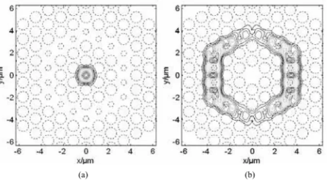
Due to the special structure of the DCCPCF, it determines there are at least two supermodes in the inner core and the outer core, respectively. One is fundamental mode, and the other is second mode. Typical field patterns in the two cores are shown in Fig. 2.
Fig. 3 shows the relations between the effective indices of the fundamental mode and the second mode versus wave-length, and the relations between the effective indices of the modes in the inner core and outer core versus wavelength.
(a) (b)
FIG. 2: Typical field patterns in these two cores; (a) In the inner core; (b)The outer core.
Solid and dashed curves correspond to ne f f of the
funda-mental mode and the second mode, respectively. And the curves marked by circle and square correspond tone f f of the
modes in the inner core and outer core, respectively. From Fig. 3, it could be found that the curves marked by circle and square intersect at a certain wavelength. The cross point corresponds to the phase matching wavelengthλp. In the Fig. 3,λp=1.548µm. Aroundλp, ne f f of the modes in the
inner core and outer core match to each other, and optical coupling takes place between the modes in the inner core and outer core. At wavelengths shorter thanλp, the effec-tive indices of the fundamental mode and the second modes are very close to those of the modes in inner core and outer core respectively. At wavelengths longer thanλp, however, the effective indices of the fundamental mode and the second mode are very close to those of the modes in outer core and inner core respectively.
FIG. 3: Relations of the effective indices versus wavelength (Curves marked by circle and square correspond to ne f f of the modes in
inner core and outer core
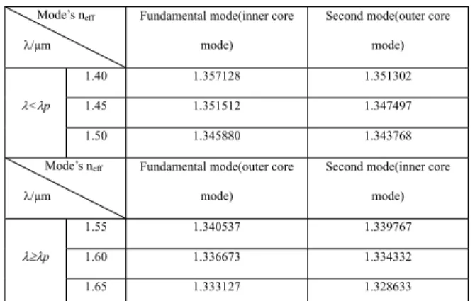
Table 1 illustrates the effective indices of the fundamental mode and the second mode with wavelength from 1.40µm to 1.65µm. It can be seen from Table 1 that, when wavelengths shorter thanλp, indices of the fundamental mode equal to
Brazilian Journal of Physics, vol. 39, no. 3, September, 2009 521
when wavelengths longer thanλp, indices of the fundamental
mode equal to those of mode in the outer core, and indices of the second mode equal to those of mode in the inner core.
TABLE 1: The effective indices of the fundamental mode and the second mode
Mode’s neff
O/µm
Fundamental mode(inner core
mode)
Second mode(outer core
mode)
1.40 1.357128 1.351302
1.45 1.351512 1.347497 O<Op
1.50 1.345880 1.343768
Mode’s neff
O/µm
Fundamental mode(outer core
mode)
Second mode(inner core
mode)
1.55 1.340537 1.339767
1.60 1.336673 1.334332 OtOp
1.65 1.333127 1.328633
(a) (b)
FIG. 4: Normalized intensities of (a) the fundamental mode and (b) the second mode as function of wavelength.
Fig. 4 is relations of normalized intensities of the funda-mental mode and the second mode versus wavelength. It can be seen from Fig.4(a) that, at wavelengths shorter thanλp,
the field is essentially confined to the inner core and the field pattern is a Gaussian shape. It matches that in the common transmission fibers. However, when wavelengths longer than λp, most of the power of the fundamental mode spreads to
the outer core and is effectively guided in the outer core. The mode field pattern is annular shape. As to Fig.4 (b), when λ<λp, the field is essentially confined to the outer core and
is maximal in the outer core. While, whenλ>λp, the field
is turn to the inner core, and the shape becomes Gaussian shape. However, the indices of mode guided in the inner core are smaller than those of outer core. So the mode guided in the outer core is the fundamental mode.
Base on above results, we can find that aroundλp, due to
optical coupling takes place between the fundamental mode and the second mode, the effective indices of these two modes have varied largely. It results in large D value atλp,
for both fundamental mode and second mode, as shown in Fig. 5. The two curves are very symmetric due to the cou-pling between the two modes. Around 1.55µm,Dof the fun-damental mode reaches about – 5850 ps/km/nm, while D of the second mode reaches about 5850 ps/km/nm.
Theoretically, there are more than two modes guided in the fibers. Hence, we should make a selective excitation of
FIG. 5: Dispersion of the fundamental and second modes.
the DCCPCF. So the fundamental mode is selected because it yields a large negative chromatic dispersion. However, in practice, when light is launched into the fiber, the high modes including second mode suffer a high transmission loss with propagation and virtually becomes extinct within a short length of the DCCPCF [3].
IV. TOLERANCES ON THE STRUCTURAL PARAMETERS
During the fabrication, the values of structural parameters would have some deviations from the values of the theoret-ical design inevitably. Therefore the influence of the chro-matic dispersion of the fiber with the deviations of the struc-tural parameters were extensively investigated. The effect of possible tolerances ind1,d2is demonstrated in Fig. 6.
(a) (b)
FIG. 6: The dispersion curves of DCCPCF; (a) Keeping fixedΛand d1, for different d2; (b) Keeping fixedΛand d2, for different d1
522 Zhao-yuan Song et al.
increasingd1, the minimum dispersion wavelength shifts to shorter wavelength side and the value of the absolute magni-tude of dispersion coefficient increases simultaneously. By comparing with Fig. 6(a) and (b), the dispersion changing trends withd1andd2are quite on the contrary. Simulations also show that 1% variation ind1andd2, changesλpby 1.2%
and 0.5%, respectively. Hence, with the acceptable toler-ance, there is very little impact on the dispersion curve of the fundamental mode. Therefore, with the result, the designed fiber can be fabricated easily.
V. CONCLUSION
Based on multipole method, a DCCPCF composed of pure silica and air is investigated thoroughly in this paper. Around 1.55µm, it exhibits a negative chromatic dispersion as high
as -5850 ps/km/nm. The chromatic dispersion and propa-gation characteristics of DCCPCF have been simulated sys-temically. The explanations to propagation states of the fun-damental mode and the second mode are given elaborately. Finally, the variation of structural parameters is investigated to evaluate the tolerance of the fabrication. As a result, the designed fiber can be fabricated easily.
ACKNOWLEDGEMENTS
This work was supported by the State Key Develop-ment Program for Basic Research of China under Grant No. 2003CB314905 and the State Key Program of National Nat-ural Science of China under Grant No. 60637010. The au-thors are grateful to the referees for their helpful comments.
[1] L.G. Nielsen, S.N. Knudsen, B. Edvold, T. Veng, D. Mag-nussen, C. C. Larsen, and H. Damsgaard, Optical Fiber Tech-nology6, 64 (2000).
[2] A.J. Antos and D. K. Smith, Lightwave Technol 12, 1739 (1994).
[3] J.L. Auguste, J. M. Blondy, J. Maury, J. Marcou, B. Dus-sardier, G. Monnom, R. Jindal, K. Thyagarajan, and B. P. pal, Optical Fiber Technology8, 89 (2002).
[4] P.P. Bishnu and P. Kamna, Opt. Commun.201, 335 (2002). [5] J.L. Auguste, R. Jindal, and J. M. Blondy, Electron. Lett.36,
1689 (2000).
[6] K. Thyagarajan, R. K. Varshney, P. Palai, A. K. Ghatak, and I. C. Goyal, IEEE Photon. Technol. Lett.8, 1510 (1996). [7] F. Gerome, J. L. Auguste, and J. M. Blondy, Opt. Lett.29,
2725 (2004).
[8] F. Gerome, J. L. Auguste, and J. M. Blondy, Optical Fiber
Communication Conference2, 22 (2004).
[9] A. Huttunen and P. Torma, Opt. Express13, 627 (2005). [10] T. Fujisawa, K. Saitoh, K. Wada, and M. Koshiba, Opt.
Ex-press14, 893 (2006).
[11] S.G. Yang, Y. J. Zhang, X. Z. Peng, Y. Lu, S. Z. Xie, J. Y. Li, W. Chen, Z. W. Jiang, J. G. Peng, and H. Q. Li, Opt. Express
14, 3015 (2006).
[12] Y. Ni, L. Zhang Lei, L. An, J. D. Peng, and C. C. Fan, IEEE Photon. Technol. Lett.16, 1516 (2004).
[13] T.P. White, B.T. Kuhlmey, R.C. McPhedran, D. Maystre, G. Renversez, C. M. Sterke, and L. C. Botten, Journal of the Op-tical Society of America B19, 2322 (2002).