SIMULATION AND IMPLEMENTATION OF CURRENT
CONTROL OF BLDC MOTOR BASED ON A COMMON
DC SIGNAL
J.Karthikeyan* Dr.R.Dhanasekaran**
* Research Scholar, Anna University, Coimbatore ** Research Supervisor, Anna University, Coimbatore
Abstract: The objective of this project is to build a simple current controlled modulation technique for brushless
dc motors. In electric traction and most other applications, a wide range of speed and torque control of the electric motor is required. The dc machine fulfills these requirements, but the dc machine requires constant maintenance. But the brushless permanent magnet motors do not have brushes and so they require less maintenance only. Brushless dc motors are widely used in applications which require wide range of speed and torque control because of its low inertia, fast response, high reliability and maintenance free. This current controlled technique is based on the generation of quasi- square wave currents using only one controller for the three phases. The current control strategy uses a triangular carrier for the power transistors which is simpler and more accurate than any other options. The advantages of this technique are: a )The stator currents are completely characterized by their maximum amplitude , b) The three phases are controlled with the same dc component , and then the phase currents are kept at exactly the same magnitude I max, c) The dc link current measurement is not required .d) phase currents are kept balanced and phase over currents are eliminatedKey words : Inverter, PSIM , BLDC motor
I. INTRODUCTION:
There are two ways to control the phase-currents of a BDCM: 1) through the measurement of the phase currents, which are compared and forced to follow a quasisquare template; 2) through the measurement of the dc link current, which is used to get the magnitude of the phase-currents, Imax. In the first case, the control is complicated, because it is required to generate three, quasisquare current templates, shifted 120 for the three phases. Besides, these current templates are not easy to follow for the machine currents, because of phase-shifts and delays introduced [8]. In the second case, it is difficult to measure the dc current, because the connection between transistors and the dc capacitors in power inverters are made with flat plates to reduce leakage inductance. Then, it becomes difficult to connect a current sensor. To avoid those drawbacks, in this paper the equivalent dc current is obtained through the sensing of the armature currents. These currents are rectified, and dc component, which corresponds to amplitude I max
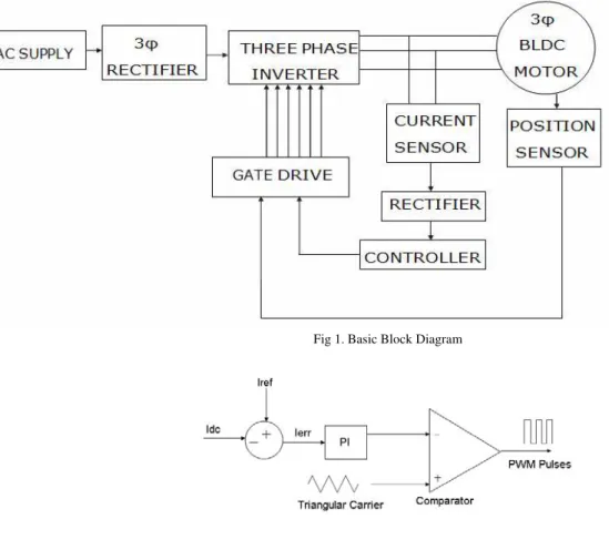
Fig 1. Basic Block Diagram
Fig 2 . Current controller block
of the original phase currents is obtained. This dc component is then used to drive the BDCM. The advantages of this strategy are: a) the stator currents are completely characterized by their maximum amplitude; b) the three phases are controlled with the same dc component, and then the phase currents are kept at exactly the same magnitude Imax; c) the dc link current measurement is not required. These characteristics allow using the triangular carrier as a current control strategy for the power transistors, which is simpler and more accurate than other modulation methods.
II. PROPOSED CONTROL SYSTEM
inverter, which are sequentially activated by the shaft position sensor. The torque is directly commanded by Iref. The larger the reference Iref, the higher the torque produced. The strategy becomes simple, because the control only needs to be in command of one dc current instead of three alternating waveforms. Another advantage of this strategy is that the modulation of the currents can be done using one of the simplest control strategies available: the “triangular carrier modulation strategy” which offers the following additional advantages: 1) the switching frequency becomes defined by the triangular carrier Fig. 2. Stator and rotor’s MMF during step change from motor to brake operation. 2) The ability to follow the template with the proposed method becomes quite accurate when triangular carrier is used 3) the hardware implementation is very simple
The control strategy also allows regenerative braking, which is very important in many applications, like electric vehicles, where energy can be returned to the battery pack. To brake the motor (regenerative braking) the stator magnetic field is reversed. This action is accomplished through the inversion of the signals given by the position sensor. The position sensor discriminates six positions each 360 electric degrees. During motor operation, the rotor moves clockwise. When the brake signal is applied, the stator field is reversed 180 electric degrees. This action produces an instantaneous change in the direction of the torque, making a fast reduction of the speed of the machine, which begins to return its energy to the dc link. The same strategy can be used for reversal of rotation of the machine
III. CIRCUIT DESIGN:
The drive system consists of a three-phase inverter, a BDC permanent magnet motor, and a dc power supply. The sensing system is divided in two parts: Position Sensor System and Current Sensor System. The first system is based on three hall effect cells placed inside the motor, and a magnetic disc in the rotor, with the same number of poles as the motor. The second sensing system is based on the current sensors.
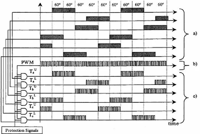
Fig. 3. Digital operation of the position sensor: (a) position sensor signals, (b) PWM signal, and (c) gating signals for the
However, the information with two sensors is complete and redundant as shown in the same Fig. 1. As it was already mentioned, the utilization of one current sensor at the dc link is not possible, because the power inverter was implemented using flat cooper plates between transistors and electrolytic capacitors. This is the common way to construct power inverters, because otherwise the leakage inductance between dc link and transistors becomes very large, producing dangerous over voltages that could destroy the power transistors.
The Control Circuit of the Fig. 1 has sub blocks of analog and digital electronic circuits (comparators, PI controller, and adder devices). As it was already mentioned, the dc signal is obtained from signal rectification of the phase currents. This rectification system uses germanium diodes to reduce the nonlinearity problem introduced by the fixed voltage drop of the diodes used in the rectifier. However, this problem becomes noticeable only when the current is smaller than 3% of the nominal value of (120 A). Then, it does not become a serious problem in the operation of the proposed method. The current is compared with a desired reference, and from this comparison, and error signal Ierr is obtained. This error signal is then processed with a PI control. The output of the PI control is compared with a triangular waveform of fixed amplitude and frequency, which gives a common and unique pulse width modulation for the three phases of the motor. This unique PWM pattern, and the information given by the position sensor, generates the modulation signals for each transistor. The PWM controls the magnitude, and the position sensor discriminates when the PWM has to be applied to each of the six transistors, creating the correct sequence for the rotation of the machine. The Fig 3 shows the digital operation of the position sensor.
IV. CURRENT CONTROLLER DESIGN
by Powersim Technologies Inc., was used.
V. SIMULATION RESULTS
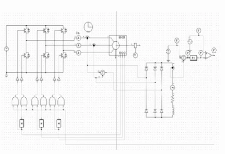
Fig 4. Simulated Circuit diagram for the proposed method using PSIM
Fig 5. Phase current Waveforms
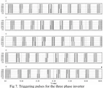
Fig 7. Triggering pulses for the three phase inverter
The simulation of the proposed control technique is done using PSIM. Fig 4. shows the closed loop simulated circuit diagram. The BLDC motor is given supply through a three phase inverter. The motor currents are sensed, rectified and then dc component is compared with a reference value, and the error in current is then processed using a PI controller. The controlled error is then compared with a triangular wave to generate the controlled PWM pulses. These pulses are then ANDed with the position sensor signals and then given to the three phase inverter switches. Fig 5 and 6 represents various simulated waveforms. Fig 7 shows the six triggering pulses for the three phase inverter.
VI HARDWARE IMPLEMENTATION:
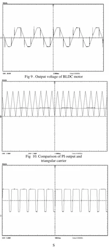
The proposed method of control is implemented with a BLDC motor of supply voltage of 24 V. The three phase inverter is constructed using MOSFET switches. The gating signal required for these switches is given through the rotor position sensor. The output waveforms are given below. The fig8 shows the Hall Effect sensor output. The fig 9 shows the output voltage waveform of the BLDC motor. Fig 10. Shows the comparison of the PI controller output and fig 11. Shows the generation of PWM pulses, which will be then combined with the Hall Effect sensor output to generate the triggering pulses for the three phase inverter.
Fig 9 . Output voltage of BLDC motor
Fig 10. Comparison of PI output and triangular carrier
S
VI. CONCLUSION
REFERENCES:
[1] T. Lowand M. A. Jabbar, “Permanent-magnet motors for brushless operation,” IEEE Trans. Ind. Applicat., vol. 26, pp. 124–129, Jan./Feb. 1990.
[2] C. C. Chan and K. T. Chau, “An overview of power electronics in electric vehicles,” IEEE Trans. Ind. Electron., vol. 44, pp. 3–13, Feb. 1997.
[3] J. M. D. Murphy and F. G. Turnbull, Power Electronic Control of ACMotors. Exeter, U.K.: Wheaton & Co., Ltd., 1988, pp. 424–428. [4] J. Dixon, S. Tepper, and L. Morán, “Practical evaluation of different modulation techniques for current-controlled voltage source
inverters,” Proc. Inst. Elect. Eng., vol. 143, pp. 301–306, July 1996.
[5] N. Hemati and M. C. Leu, “A complete model characterization of brushless dc motors,” IEEE Trans. Ind. Applicat., vol. 28, pp. 172–180, Jan./Feb. 1992.
[6] Kun Wei , Zhengli Lou , Zhongchao Zhang, “Research on the Commutation Current Prediction Control in Brushless DC Motor” [7] H.C.Chen and C.M. Liaw , Current Mode Control and Intelligent Commutation Tuning for Sensor less BDCM Drive
[8] Juan W. Dixon and Iván A. Leal “Current Control Strategy for Brushless DC Motors Based on a Common DC Signal ”
[9] Sung-In Park, Tae-Sung Kim, Sung-Chan Ahn, Dong-Seok Hyun ,“An Improved Current Control Method for Torque Improvement of High- Speed BLDC Motor ”
AUTHORS:
J.Karthikeyan:
He received the B.E. degree from M.K.University Madurai. and M.E degree in Power Electronics & drives from Bharadithasan university,Trichy. He had experience in technical profession for 10 years. He has authored Four books in Electrical Drives & controls .He is presently doing his research work in Anna University,Coimbatore. He is an ISTE life member and also an member of Institution of Engineers (India).His current research interests include are control of Electrical machines using Power Electronics and Converter circuits.
Dr.R.Dhana sekaran: