Abstract—In order to improve the performance of bearingless brushless DC motor, a closed-loop suspended force controller combining the discrete space voltage vector modulation is applied and the direct torque control is presented in this paper. Firstly, we increase the number of the control vector to reduce the torque ripple. Then, the suspending equation is constructed which is spired by the direct torque control algorithm. As a result, the closed-loop suspended force controller is built. The simulated and experimental results evaluate the performance of the proposed method. The more advantage is that the proposed algorithm can achieve the fast torque response, reduce the torque ripple, and follow ideal stator flux track. Furthermore, the motor which implants the closed-loop suspended force controller cannot only obtain the dynamic response rapidly and displacement control accurately, but also has the characteristics of bearingless brushless DC motor (such as simple structure, high energy efficiency, small volume and low failure rate).
Index Terms—Bearingless brushless DC motor, direct torque control, discrete space voltage vector modulation, closed-loop suspended force control.
Original Research Paper DOI: 10.7251/ELS1317009S
I. INTRODUCTION
HE bearingless brushless DC motor is a new kind of motor, which has two windings fixed in the stator. One winding is used to control system’s torque, and the other is used to provide the suspension. The bearingless brushless DC motor has several
Manuscript received 7 April 2013. Received in revised form 23 May 2013. Accepted for publication 5 June 2013.
This work was supported by the priority academic program development of Jiangsu higher education institutions and research and innovation plan of university graduate in Jiangsu province (CXLX11_0586).
Zhanshi Sheng is with the School of Electrical and Information Engineering, JiangSu University, Zhenjiang 212013, China (corresponding author, phone:+135-05-286-768; e-mail: [email protected]).
Xiaolian Wang is with the School of Electrical and Information Engineering, JiangSu University, Zhenjiang 212013, China.
Fei Tan is with the School of Electrical and Information Engineering, JiangSu University, Zhenjiang 212013, China.
Weiran Wang is with the School of Electrical and Information Engineering, JiangSu University, Zhenjiang 212013, China.
advantages, such as simple structure, low fault-rate, small volume and high efficiency of energy conversion. Furthermore, the motor has high speed because its rotor suspends in the air. Those merits make the motor popular in industrial community including medical industry, aerospace and chemical process.
Direct torque control (DTC), the most advanced AC drive technology, has been used in the bearing brushless DC (BLDC) motor recently [1]–[4]. Reference [5] deduced the mathematical formulas to describe the suspended force of bearingless brushless DC motor based on the principle of bearingless permanent magnet synchronous motor. Those equations have laid the foundation for the DTC. Reference [6] proposed a basic control method for the bearingless brushless DC motor. They divided the system into the torque part and suspension part by using the theory of independent suspension subsystem. The torque part was managed by the traditional double closed loop controller, and the suspension part was manipulated by the hysteresis current controller. The shortcoming of the method is that the precision is low and its speed is slow. The DTC has been used in brushlees DC motor, which solves the difficulties of the non-sine and shut-off phase [7]–[10]. But it has not been used in the bearingless brushless DC motor. In order to improve the performance of bearingless brushless DC motor, the DTC which combines the discrete space voltage vector (DSVMDTC) is presented in this paper. The simulations evaluate the proposed method.
II. THE SUSPENDED FORCE MODEL OF BEARINGLESS
BRUSHLESS DCMOTOR
The air-gap flux of bearingless brushless DC motor consists of three parts: the permanent magnetic potential of rotor, the current magnetic potential of torque winding, and the current magnetic potential of suspended winding. The permanent magnetic potential of rotor and the current magnetic potential of torque winding are the square wave. The permanent magnetic potential of rotor changes with the rotor’s position varying. Moreover, the current magnetic potential of torque winding has step change with the sector difference. So the space distribution of air-gap flux is very complex. In order to simplify the deduced process, the hypothesis is made by referring to [11].
Combined Discrete Space Voltage Vector with
Direct Torque Control for Bearingless Brushless
DC Motor and Closed-Loop Suspended Force
Control
Zhanshi Sheng, Xiaolian Wang, Fei Tan, and Weiran Wang
The Fig. 1 is a typical main circuit of brushless DC motor, which is a square wave control system. Controller triggers the inverter transistor according to the position sensor’s information.
A phase axis is set as the x axis and the angle between the x
axis and the clockwise of d-axis of the rotor is defined as the angle of rotor θ. The symbols a, b and c are used to represent the on/off condition of the three-phase winding A, B and C [12].
The flux of stator air gap is: 1
t f
F=F + +F F (1)
where Ft is the flux which is produced by the current through
torque control winding and this flux is a phase change function;
F1 is the flux which is produced by the current through
suspension control winding and its value is F1=Flcos(θ-θl); Ff is
the flux which is produced by the permanent magnet and its value also phase-change.
The mathematical model of suspension force in bearingless brushless DC motor is different under the different modes of the torque windings. It causes the difficulty in decoupling control of suspension part. So it needs to establish a uniform suspension control model. A parameter P is defined to denote the state variable, and the value is relevant to the angle of rotor. The values of the P are shown in the Table I:
TABLEI
THE PARAMETER OF THE SUSPENDED FORCE MODEL
P 0 1 2 3 4 5 a 0 -1 -1 0 1 1 b 1 1 0 -1 -1 0 c -1 0 1 1 0 -1
In Table I, a, b, c is defined as three-phase torque control switch’s state on/off. Taking the A phase for example, a=0 means the two switching tubes (up bridge arm and down bridge arm) of A phase are all turned-off; a=1 means the up bridge arm is turned-on and the down bridge arm is turned-off; a=-1 means the up bridge arm is turned-off and the down bridge arm is turned-on. The suspension control model of bearingless brushless DC motor is defined as follows:
(
)
0
2 1 2
2 4 cos 2 2 3 sin
2 3
x f l r l
eg
rh P
F F F F F
l
μ ⎡ θ θ ⎛θ π⎞⎤
= ⎢ − + ⎜ − ⎟⎥
⎝ ⎠
⎣ ⎦
(2)
(
)
0
2 1 2
2 4 sin 2 2 3 cos
2 3
y f l r l
eg
rh P
F F F F F
l
μ ⎡ θ θ ⎛θ π⎞⎤
= − ⎢ − − ⎜ − ⎟⎥
⎝ ⎠
⎣ ⎦
(3)
Where r is the radius of rotor, h is the length of axial, legis
the length of air gap between the stator and rotor, F1 is the
torque flux which produced by the current through the torque winding, F2 is the suspended flux which produced by the
current through the suspension winding, Ff is the flux which
produced by the permanent magnet, θ1 is the phase of
suspended flux’s base wave, θr is the angle of rotor, θt is the
phase of torque flux’s base wave.
III. DIRECT TORQUE CONTROL OF THE BEARINGLESS
BRUSHLESS DCMOTOR
A. The State of the Inverter for Bearingless Brushless DC
Motor
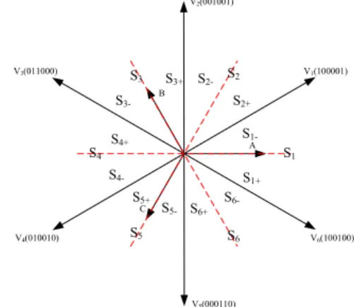
We use six numerals to express the states of six switching tubes in BLDC-DSVMDTC. Each numeral expresses one switching tube’s state. Zero (0) denotes the turn-off and one (1) means turn-on. So the six voltage vectors V1, V2, V3, V4, V5, V6
are (100001), (001001), (011000), (010010), (000110), (100100) and the zero vector V0 is (000000) as shown in Fig. 2.
The stator flux is complex in the BLDC-DTC. Under the linear condition, the flux leakage can be ignored. Then, the stator flux ψs is the vector sum of the armature flux ψα and the
rotor flux ψf.
s α f
ψ
=
ψ
+
ψ
(4)The ψf is produced by rotor permanent magnet and the value
is constant under the linear condition. The ψαisproduced by stator current and its value always varies. The phase angle of stator current can be deduced from the state of back-EMF.
B. Discrete Voltage Space Vector Modulation
The more the voltage space vectors use, the better the tracking effect is. As a result, the track of synthesis flux will be closed to the ideal track. This is the idea of SVPWM. But the computational burden will increase, which reduces the real-time performance of system. To overcome this problem, the DTC combining the discrete voltage space vector modulation is presented (DSVM-DTC) and the finite vectors are used to compose the new vector in a cycle. The method can get the better control effect and reduce the torque ripple greatly [13].
There are m basic voltage vectors in one cycle T and one
Fig. 1. The main circuit of brushless DC motor control system.
A B
C
V1(100001) V2(001001)
V3(011000)
V4(010010)
V5(000110)
V6(100100)
S1
S1+
S
1-S2
S3
S4
S5 S6
S2+
S3+
S4+
S5+
S6+
S
2-S
3-S
4-S
5-S
basic voltage vector works T/m. It actually gets the duty cycle which can change from 1/m to 1. As shown in Fig. 3, there are four basic voltage vectors when system works in sector S1. Then, more than 50 new voltage vectors can be composed in different duty cycle. The vectors which are perpendicular to the track of flux are selected. Then the best vector can be determined according to the sign of flux and torque.
The 9 hysteresis comparators are selected to get the flux sign and 8 hysteresis comparators are used to get the torque sign. Due to the number of the voltage vectors increase in one cycle, it is possible to refine flux and torque condition and select the best vector. The Fig. 4(a) is flux hysteresis comparison device which has nine layers. Flux difference=given Flux-real Flux.
ε1ψ, ε2ψ, ε3ψ, ε4ψ are hysteresis tolerances. If the Flux difference Δψ>ε4ψ, the given Flux is much greater than the real Flux and it
need increase the flux greatly; If the Flux difference Δψ>ε3ψ,
the given Flux is greater than the real Flux and it need increase the flux. If the Flux difference Δψ>ε1ψ, the given Flux is greater
than the real Flux slightly and it need increase the flux slightly. Similar to the upper condition, the sign can be got when
Δψ<-ε1ψ, Δψ<-ε2ψ, Δψ<-ε3ψ, Δψ<-ε4ψ, but the flux should be
decreased. The Fig. 4(b) is torque hysteresis comparison device which has eight layers. Torque difference= given Torque-real Torque. ε1T, ε2T, ε3T, ε4T are hysteresis tolerances and the state
analysis of torque is similar to the flux.
Fig. 3. Sector S1 (S1- S1+) of the vector choose.
In order to make the best use of voltage vector, the speed can be segmented as several parts. Then the refining methods can be used in the low-speed part and high-speed part (the refining sector divides the original sector into two parts equally). As shown in Fig. 3, the 6 sectors system is segmented into 12 sectors system equally. The refining sector can restrain torque ripple further by locating the flux at the sector. Then the prefect control effect can be achieved.
IV. THE CLOSED-LOOP SUSPENSION FORCE CONTROL OF
BEARINGLESS BRUSHLESS DCMOTOR
The traditional algorithm adjusts the flux of suspended force by using the current of suspension winding. This pattern can get the amplitude and direction of suspended force indirectly. But it is an open-loop algorithm, so the precision is low and the response is slow. Inspired by the direct torque control, the suspended force can be regarded as amplitude which can be adjusted according to ψ2. And the phase angle depends on the
state of inverter and rotor angle. The state of inverter is related to the rotor position [15].
Deduced by (2) and (3),
(
)
1 2cos 2 2 1 2sin
3
m f l r m l
P
Fα k k
π
ψ ψ θ θ ψ ψ ⎛θ ⎞
= − + ⎜ − ⎟
⎝ ⎠ (5)
(
)
1 2sin 2 2 1 2cos
3
m f l r m l
P
Fβ k k
π
ψ ψ θ θ ψ ψ ⎛θ ⎞
= − − + ⎜ − ⎟
⎝ ⎠ (6)
The variation of flux produced by the suspension control winding can be known when the synthetic suspension force vector changes from kth to (k+1)th.
The synthetic suspended force vectors at k and k+1 are:
( )
( ) (
2)
( )
3
l r p l
P F k = F k ∠ θ − θ +F k ∠⎜⎛θ − π⎞⎟
⎝ ⎠ (7)
(
1)
(
1) (
2)
3
l r
p l
F k F k
P F
θ θ θ
π
θ θ
+ = + ∠ − + Δ
⎛ ⎞
+ ∠⎜ − + Δ ⎟
⎝ ⎠
(8)
Decompose the suspended force of k and k+1 moment in αβ coordinate system and the difference of suspended force can be formulated as:
(
1)
( )
F F k F k
Δ = + − (9)
Cψ
1ψ
ε
*
s s s
ψ ψ ψ
Δ = −
2ψ
ε ε3ψ ε4ψ
1ψ
ε
−
2ψ
ε
−
3ψ
ε
−
4ψ
ε
−
(a)Flux hysteresis comparison device which has nine layers
T C
1T
ε *
e e e
T T T
Δ = −
2T
ε ε3T ε4T
1T
ε − 2T
ε − 3T
ε − 4T
ε −
(b)Torque hysteresis comparison device which has eight layers
The component in αβ coordinate is: ( ) ( ) ( ) ( ) ( ) ( ) ( ) ( ) ( ) ( ) ( ) ( ) ( ) ( ) ( ) 1 2 1 2 2 2 2 2 1 2 1 2 1
1 cos cos 2 1 sin sin 2
1 sin cos 3 1 cos sin
3 cos cos 2
s
f s l r
f s l r
f s l
f s l
f s l r
f s
F F k F k
k k k k P k k P k k k k k k
α α α
ψ θ θ θ
ψ θ θ θ
π
ψ θ θ
π
ψ θ θ
ψ θ θ
ψ
Δ = + −
= + + Δ
+ + + Δ
⎛ ⎞
+ + + Δ ⎜ ⎟
⎝ ⎠
⎛ ⎞
− + + Δ ⎜ ⎟
⎝ ⎠ − − ( ) ( ) ( ) 2 2 2 2
in sin 2
sin cos 3 cos sin
3
l r
f s l
f s l
P k k P k k θ θ π ψ θ π ψ θ ⎛ ⎞ − ⎜ ⎟ ⎝ ⎠ ⎛ ⎞ + ⎜ ⎟
⎝ ⎠ (10)
( ) ( ) ( ) ( ) ( ) ( ) ( ) ( ) ( ) ( ) ( ) ( ) ( ) ( ) ( ) 1 2 1 2 2 2 2 2 1 2 1 2 1
1 sin cos 2
1 cos sin 2
1 cos cos
3
1 sin sin
3
sin cos 2
f s l r
f s l r
f s l
f s l
f s l r
f s
F F k F k
k k k k P k k P k k k k k k
β β β
ψ θ θ θ
ψ θ θ θ
π
ψ θ θ
π
ψ θ θ
ψ θ θ
ψ Δ = + −
= − + + Δ
+ + + Δ
⎛ ⎞
+ + + Δ ⎜ ⎟
⎝ ⎠ ⎛ ⎞
+ + + Δ ⎜ ⎟
⎝ ⎠ + − ( ) ( ) ( ) 2 2 2 2
cos sin 2
cos cos
3
sin sin
3
l r
f s l
f s l
P k k P k k θ θ π ψ θ π ψ θ ⎛ ⎞ − ⎜ ⎟ ⎝ ⎠ ⎛ ⎞ − ⎜ ⎟
⎝ ⎠ (11)
Where kf1 is suspension force coefficient 1, kf2 is
suspension force coefficient 2, Δθ is the change angle of suspension force.
The fluxes of suspension control winding at k and k+1 moment are:
( )
( ) ( )
2 2
s k s k l
ψ =ψ ∠ θ (12)
(
)
(
) (
)
2 1 2 1
s k s k l
ψ + =ψ + ∠ θ + Δθ (13)
Decompose the flux of suspension control winding at k and
k+1 moment and the flux difference of suspension control winding is:
(
)
( )
2 2
1
2s s
k
sk
ψ
ψ
ψ
Δ
=
+ −
(14)The component in αβ coordinate is:
(
)
( )
(
) (
)
( )
2 2 2
2 2
1
1 cos cos
s s s
s l s l
k k
k k
α α α
ψ
ψ
ψ
ψ
θ
θ ψ
θ
Δ = + −
= + +Δ − (15)
(
)
( )
(
) (
)
( )
2 2 2
2 2
1
1 sin sin
s s s
s l s l
k k
k k
β β β
ψ
ψ
ψ
ψ
θ
θ ψ
θ
Δ = + −
= + +Δ − (16)
Substitute the (10) and (11) by (15) and (16), so
( ) ( )
( )
( )
2 1 2 2 2 2cos 2 sin 2 sin 2 cos 2
sin 3 cos 3 cos sin 3 3 s r r f s r r s f s F k F P P k P P α α β β α β ψ θ θ ψ θ θ
π π ψ
ψ
π π
Δ Δ
⎡ ⎤ ⎡ ⎤⎡ ⎤
=
⎢Δ ⎥ ⎢ − ⎥⎢Δ ⎥
⎣ ⎦
⎣ ⎦ ⎣ ⎦
⎡− ⎤⎡Δ ⎤
⎢ ⎥
+ ⎢ ⎢ ⎥
⎥ Δ⎣ ⎦
⎢ ⎥ ⎣ ⎦ (17)
( ) ( )
( ) ( )
2 1 2 2 sin coscos2 sin2 3 3
sin2 cos2 cos sin
3 3
s r r
f f
s r r
P P
F F
K k k
F P P F
α α α
β β β
π π
ψ θ θ
ψ θ θ π π
⎧ ⎡− ⎤ ⎫
Δ Δ Δ
⎡ ⎤= ⎪ ⎡ ⎤⎡ ⎤+ ⎢ ⎥⎡ ⎤⎪
⎨ ⎬
⎢Δ ⎥ ⎢ − ⎥⎢ ⎥Δ ⎢ ⎥⎢ ⎥Δ
⎣ ⎦
⎣ ⎦ ⎪⎩ ⎣ ⎦ ⎢⎣ ⎥⎦⎣ ⎦⎪⎭
(18)
( )
( )
2 2 1 2 1 2
1
2 sin 2 cos cos2 sin
3 3
f f f f r r
K
P P
k k k k θ π θ π
=
⎡ ⎤
+ + ⎣ − ⎦
(19)
Equations (17) and (18) can be seen as the coordinate transformation between the flux difference and the suspended force difference. Then, the suitable space voltage vector is selected to compose the flux difference of the suspension control winding. The relationship between the suspended force difference and the flux difference of the suspension control winding is obtained. The amplitude and direction of suspension can be controlled by flux vector. In this algorithm, the suspension force is a closed-loop control and anti-interference performance of system is enhanced greatly.
V. THE SIMULATION AND EXPERIMENT
2 θ * 1d ψ * 1q ψ * s
ψ ψs
*
r
n ωr
r
n
/
sα βs
ψ Sψ * e T e T 1 θ T S s ψ r n Fig. 5. BLDC-DSVMDTC’s simulation and experiment.
In this simulation, the parameters of bearingless brushless DC motor are: Rated voltage U = 50 V, Rated speed
n = 1500 rad/min, Rated current I = 5 A, the resistance of torque winding R1s = 0.48 Ω, the inductance of torque winding
L1s = 8.5×10⁻³ H, the mutual inductance of torque winding
L1m = 0.0006 H, the resistance of suspended force control
winding R2s = 0.42 Ω, the inductance of suspended force
control winding L2s = 6.5×10⁻³ H, the mutual inductance of
suspended force control winding L2m = 0.0004 H, the
coefficient of back EMF Ke = 0.075 V·s/rad, the coefficient of
rotational inertia J = 0.8×10⁻³ kg·m2, the rotor quality m = 2.85 kg [14].
The speed from zero to the rated speed (8000 rad/min) only needs 0.17 s and the overshoot volume is small. As shown in the Fig. 6, there are very small fluctuations at 0.17 s and the speed immediately stabilizes at rated speed.
The Fig. 7 is the typical track of stator flux. The track is not a circle. It is irregular circle when the rotor rotates to switch area. The flux will appear an obvious variation.
Fig. 8(b), the torque responds a 3 N·m change at 0.32 s, the system controls the torque and stabilizes at 1±0.08 N·m.
It means the change of velocity influences the torque greatly. The torque stabilizes only needing 0.07 s. So, the control system responses quickly and it has a good adjustment about the input change.
0.0 0.1 0.2 0.3 0.4 0.5 -2
0 2 4
T
o
rque(Nm)
time(s)
Torque
(a) Torque drop from 1 N to 0.5 N at 0.25 s
0.0 0.1 0.2 0.3 0.4 0.5 0
200 400 600 800 1000 1200 1400
Speed(r
ad/mi
n)
time(s)
Speed
(b) The speed response when torque drop from 1 N to 0.5 N at 0.25 s Fig. 9. The response of speed and torque in the process of torque change.
-0.10 -0.05 0.00 0.05 0.10
-0.10 -0.05 0.00 0.05 0.10
Y ax
is
X axis
The stator flux track
(a) Flux track of BLDC-DSVMDTC’s simulation
(b) Flux track of BLDC-DSVMDTC’s experiment Fig. 7. The track of stator flux.
0.0 0.1 0.2 0.3 0.4 0.5
-200 0 200 400 600 800 1000 1200 1400 1600
S
pee
d(
rad/
m
in)
time(s)
Speed
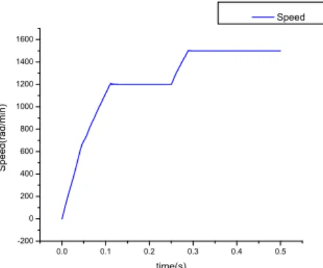
(a) Speed rose from 1200 rad/min to 1500 rad/min at 0.25 s
0.0 0.1 0.2 0.3 0.4 0.5 -2
0 2 4
T
o
rque(Nm
)
time(s)
Troque
(b) The torque response when speed rose from 1200 up to 1500 rad/min at 0.25 s
Fig. 8. The response of speed and torque in the process of speed up.
0.0 0.1 0.2 0.3 0.4 0.5 0
2000 4000 6000 8000
sp
eed
(
rad
/m
in)
time( s)
speed
The Fig. 9(a) is torque change about DSVM-DTC and the Fig. 9(b) is speed response about the torque change.
Similar to the Fig. 8, the Fig. 9 also evaluates the fast response of the control system. It has a good adaptive performance about the input change. However, the velocity is almost not affected when the torque changes.
(a) The cycle step representation of BLDC-DSVMDTC’s speed which rose from 1200 rad/s to 1500 rad/s
(b) The cycle step representation of BLDC-DSVMDTC’s torque which rose from 2.5N to 3.5N
Fig. 10. Results of speed and torque change.
The result of step change in the velocity is shown in the Fig. 10(a). There is a step signal at the channel 1 of oscillograph, and its period is 7 s. The actual velocity at the channel 2 is detected by photoelectric encoder. We can see that the velocity tracks the input step signal and the overshoot is small (0.2 V). The motor only need 1.6 s to reestablish the speed. The torque step change is shown in the Fig. 10(b). It proves that the DSVM-DTC can suppress the torque ripple and keep the advantages of rapid response.
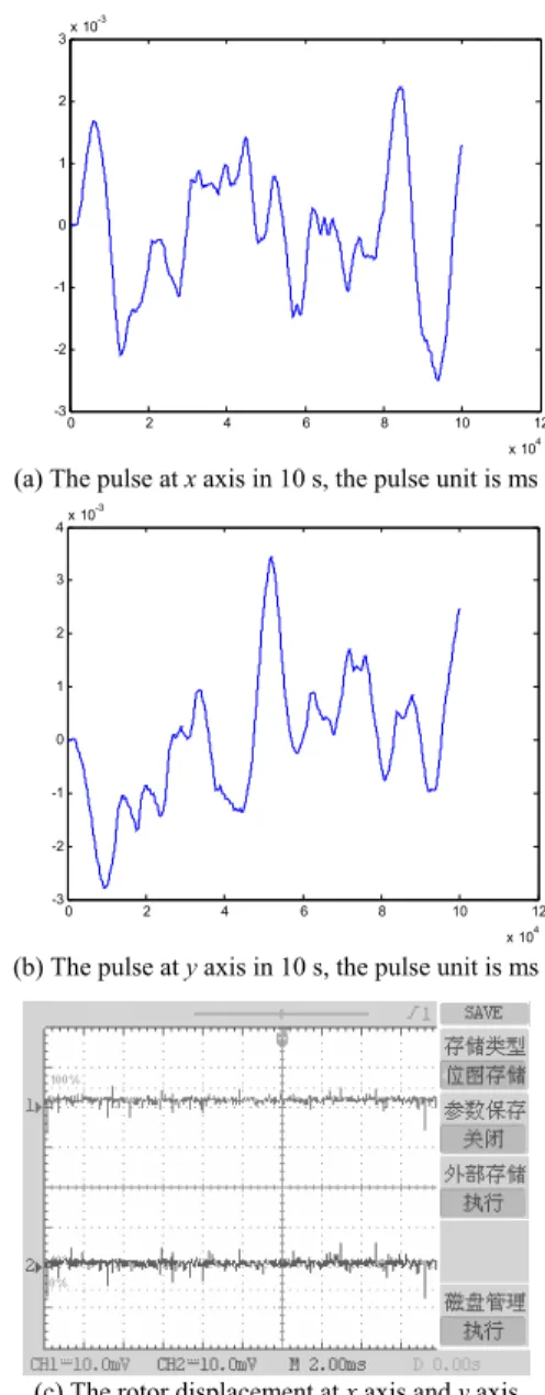
In order to demonstrate the anti-interference performance, the disturbances (1 N) are imported in x-axis and y-axis respectively. The Fig. 11(a) and Fig. 11(b) show the results. The unit is ms. It can be seen that the center and amplitude of the rotor impulse along the xy axis are 0 and 3×10⁻³ ms respectively. The Fig. 11(c) shows the displacement of rotor along the xy axis. The per-unit value is 1×10⁻³ ms/1mv. The displacement of x-axis shakes by 0.5 mv as the center and y axis shakes by 0.1 mv as the center. The amplitude also is about 2.5 mv.
VI. CONCLUSION
A DTC combined with the discrete space voltage vector is proposed to control the closed-loop suspended force of the bearingless brushless DC motor in this paper. The proposed algorithm controls the torque part and increases the number of vectors which are used to compose the new control vector. Comparing with the methods mentioned in the literatures, the
algorithm takes the characteristics of flux periodic change and the torque ripple in direct torque control into consideration. It uses the discrete space vector modulation to suppress the torque ripple and makes the ripple not affect the suspension of rotor. The more important is that the closed-loop suspended force control formula is deduced for the bearingless brushless DC motor. The simulated and experimental results show that the proposed method can get the quick response of the torque. The torque ripple is low and it can track the ideal stator flux trajectory. Furthermore, the accuracy is high and the performance of suspended force control is good. The bearingless brushless DC motor packed with the proposed method has several advantages, such as simple structure, high energy efficiency, small volume and low failure rate. So, it is suitable for the higher demand occasion of motor.
REFERENCES
[1] J. Gao. 2007. The Integreted Research of Direct Torque Control of Brushless DC Motors, Nanjing university of aeronautics and astronautics.
0 2 4 6 8 10 12
x 104 -3
-2 -1 0 1 2 3x 10
-3
(a) The pulse at x axis in 10 s, the pulse unit is ms
0 2 4 6 8 10 12
x 104 -3
-2 -1 0 1 2 3 4x 10
-3
(b) The pulse at y axis in 10 s, the pulse unit is ms
(c) The rotor displacement at x axis and y axis
[2] Q. T An, L. Z Sun, C Liu, L Sun. 2010. Flux linkage self-control based direct torque control of brushless DC motor, Zhongguo Dianji Gongcheng Xuebao/Proceedings of the Chinese Society of Electrical Engineering, Vol. 30, no. 12, pp. 86-92.
[3] S. B Ozturk and A. H Toliyat. 2011. Direct torque and indirect flux control of brushless DC motor, IEEE/ASME Transactions on Mechatronics, Vol. 16, no. 2, pp. 351-360.
[4] H. F Wei, P. P Li, G. H Liu and H. P Jia. 2009. A kind of BLDCM DTC with simplified structure, Journal of Jiangsu University(Natural Science Edition), Vol. 11, pp. 606-609.
[5] C. Jie. 2010. The Study of Bearingless and Brushless Dc Motor with Control System, Nanjing university of aeronautics and astronautics. [6] L. Jia. 2009. Principle and Control Techology of Bearingless Brushless
DC Motors, Jiangsu university.
[7] Z. L Yin. 2009. Direct Torque Control of Brushless DC Motors, Jiangsu university.
[8] J. Gao, Y. W Hu, W. X Huang and Z. F Huang. 2007. The Direct Self Control of Brushless DC Motor Based on the Hexagon Locus of Stator Flux Linkage, Proceedings of the CSEE, Vol. 5, pp. 64-69.
[9] X. X Liu, W. R Wang, W. 2010. DSVM and duty ratio control combined direct torque control for bearingless induction motor, 2010 Chinese Control and Decision Conference, pp. 2025-2030.
[10] W. R Wang, X. X Liu, H. B Wang and X. Zhu. 2012. Adapted genetic algorithm and 5 levels control combined low-speed improvement Direct Torque Control, Applied Mechanicsand Materials, Vol.130-134, pp. 426-429.
[11] H. X Wu. 2009. Application Notes for motor drive and control ASIC, China Electric Power Press.
[12] Q. D Guo and X. M Zhao. 2008. Brushless DC motor principles and techniques of application, China Electric Power Press.
[13] X. M Xue. 2010. Ripple suppression method and device of brushless DC motor electromagnetic torque. CN201010118230.X.
[14] M. S Ooshima, C. Takeuchi . 2011. Magnetic suspension performance of a bearingless brushless DC motor for small liquid pumps, IEEE Transactions on Industry Applications, Vol. 47, no. 1, pp. 72-78. [15] Z. F Huang, Y. W Hu, J. Gao, and W. X Huang. 2007. Improvement of