International Journal for Quality Research 10(3) 523–546 ISSN 1800-6450
Cristiano Fragassa
1Martin Ippoliti
Article info: Received 06.12.2015 Accepted 07.03.2016 UDC – 332.05 DOI – 10.18421/IJQR10.03-06
TECHNOLOGY ASSESSMENT OF TIRE
MOULD CLEANING SYSTEMS AND
QUALITY FINISHING
Abstract: A modern tire merges up to 300 different chemical elements, both organic and inorganic, natural and synthetic. During manufacturing, various processes are present such as mixing, calendering and extrusion, forming dozens of individual parts. Then, moulding and vulcanization inside special moulds provides the tire its final shape. Since the surface quality of moulds strongly affects the quality of tire, mould cleaning is a fundamental aspect of the whole tire production and cleaning techniques are in continuous development. This investigation proposes a global technology assessment of tire mould cleaning systems including uncommon solutions as multi-axis robots for cleaning on board by laser or dry ice, or ultrasonic cleaning which use cavitation. A specific attention is also focused on the industry adoption of spring-vents in moulds and how they are influencing the development the quality of final products. Keywords: Tire Industry, Moulds, Laser cleaning, Dry ice cleaning, Ultrasonic cleaning, Spring-vents
1.
Overview of tire
11.1.
Brief history
The first pneumatic tire was patented by Robert William Thomson in 1845. He also applied for a patent in the US, which he received in 1847 (U.S. Patent No. 5,104, 1847). This tire, with an inner tube, failed to replace the solid rubber tire due to resistance problems. John Boyd Dunlop, developed a similar but improved pneumatic tire in 1888 (British Patent No. 10,607, 1888). The radial tire was patented in 1915 by Arthur W. Savage (U.S. Patent No. 1,203,910, 1915). After the expiry of Savage’s patent, Michelin
1
Corresponding author: Cristiano Fragassa email: [email protected]
patented its radial tire in 1946 and started the sales since the end of the 40s. Radial tires were used in the US only from the 60s (Eberhart, 1965).
1.2.
Tire types
The tires can be classified according to their structure. It is then possible to distinguish 4 types:
Pneumatic tire: inflated hollow tire, retains its shape due to the air pressure, and equipped with air chamber or tubeless (CBP, 2014).
Solid tire: Made by molding, a solid tire is composed of several layers of different thickness and compound, which form a composite structure (Figure 1). Steel rings are often used as reinforcement (Suripa and Chaikittiratana, 2008). Solid tires are among the most important engineering components in heavy industry (Suripa and Chaikittiratana, 2008). They are mainly used in forklifts and in various types of industrial vehicles, but also on karts, scooters and lawn mowers (CBP, 2014).
Figure 1. Cutaway of a solid tire [Courtesy of Continental]
Cushion tire: It is a solid tire, however equipped with a sealed internal air space rather than containing pressurized air in order to maintain the shape (CBP, 2014).
1.3. Structure of a pneumatic tire
The main functions of a tire are (Gough, 1981; Peled, 2015):
To support the weight of the vehicle;
To absorb the irregularities of grounds;
To provide traction;
To ensure stability and directional control of the vehicle.
During several decades other characteristics have been added to these basic functions, on demand of the market, such as increased wear resistance, homogeneous response to each condition and increasing security. Finally, the tire was expected to contribute to reducing fuel consumption. As emerged from the research prepared by the Centro Pio Manzù (1987), this led to a change of perspective, particularly in the automotive industry. The tire cannot be considered just a mere commodity anymore, but it assumes the role of a real customer technical support. In the automotive sector, the quality of a product does not generally depend only on its performance, but it is a merging of different factors between technological aspects and clients satisfaction (Fragassa et al., 2014). Tires are not an exception, there are no compromises as regards their safety and reliability (Peled, 2015), and they are subject to constant evolution.
Figure 2. Schematic structure of a radial tire [Courtesy of Wikimedia Commons]
The structure of a tire may vary depending on the manufacturer and the intended use. It is possible to identify some basic elements (Figure 2):
Steel belts: Reinforcements made of steel wires coated with rubber. They are positioned between the carcass and the tread. Steel belts, crossed with each other, optimizes the directional stability and rolling resistance (Koštial et al., 2012).
Nylon cap: One or two nylon belts placed over the steel belts and inclined at 0° to the rolling direction. They are used in high-end tires and should improve the resistance to the speed.
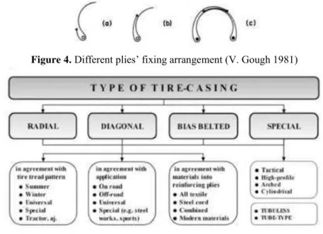
Carcass: It bears the inflation pressure. By wringing, it transmits forces between the tire and the ground. It consists of several crossed plies (Shuy, 1964). Plies are rubber layers with a low elastic modulus, which are reinforced by high modulus cords. These cables can be natural textile, synthetic polymers, especially Nylon, polyester, Rayon, glass fiber or be steel cables (Koštial et al., 2012; Lindenmuth, 2006; Gough, 1981). The number of plies depends on the type and the size of the tire and by the inflation pressure (Gough, 1981). Plies are turned around bead (Figure 3). The height to which the plies are taken after they have passed round the bead can be low or high, or the plies' extremity can extend across together, as in Figure 4. In this case the plies can be arranged to give extra carcass strength in the central region of the tire compared with the sidewalls (Gough, 1981). Standard types of tires are diagonal (or “bias”), radial and bias belted (Figure 5). In diagonal or bias tires plies are crossed at 36° (Eberhart, 1965). In radial tires, as suggested by their name, the plies should be positioned radially, thus with an angle of 90° with respect to the rolling direction. As shown in Gough, 1981, this solution will wear poorly because the shear modulus of cord-rubber is very small. The optimum angle is between 70° and 75°. Radial ply tires generate less heat during use, have lower rolling
resistance and better high-speed performance. By contrast, the greater complexity of construction leads to an increase in costs (Lindenmuth, 2006). Bias belted tires are bias tires with belts added in the tread region (Lindenmuth, 2006).
Shoulder: Part between the sidewall and the tread. Help maintain a smooth belt contour and insulate the body plies from the belt edges (Lindenmuth, 2006).
Sidewall: It bears most of the weight of the vehicle and, for this reason, it must be strengthened properly. It also protects the carcass from the weather conditions (Koštial et al., 2012).
Bead chafer: Side part in contact with
the wheel’s rim. It partially envelops the
plies Figure 2 and is mainly made of metal. It should ensure the adhesion between tire and wheel and improve air tightness.
Bead wire: Ring consisting of bronze-coated or brazed steel wires bronze-coated with rubber (Koštial et al., 2012; Lindenmuth, 2006; Shuy, 1964). It should ensure the coupling between tire and rim and transmit power.
Bead filler: Also called bead apex, its characteristics affect handling (Lindenmuth, 2006).
Liner: Inner layer that functions as an inner tube.
Figure 4.Different plies’ fixing arrangement (V. Gough 1981)
Figure 5. Type of tire-casing (Koštial et al, 2012)
1.4.Composition of the compound
The compound is composed of several elements (Table 1), a typical car tire contains about 60 raw materials (Lindenmuth, 2006). The compounds can vary depending on the manufacturer and the objective sought, that
depends on the intended use of the tire. For example, for a competition car the objective may be to optimize performance. For long distance vehicle, as truck and bus, the usual aim is to minimize the rolling friction, then to limit fuel consumption and tire usury.
Table 1. Compound composition (Evans, 2006)
Ingredients Car Lorry OTR
Rubber/Elastomers 47% 45% 47%
Carbon Black 21.5% 22% 22%
Metal 16.5% 25% 12%
Textile 5.5% -- 12%
Zinc Oxide 1% 2% 2%
Sulphur 1% 1% 1%
Addictives 7.5% 5% 6%
Carbon-based materials, total 74% 67% 76%
Elastomers: These are materials able to resume the original shape and size, even if greatly deformed by stress, once such stress has been removed (Campbell, 1963; Mark, 1943). They are characterized by a mainly amorphous structure, with low elastic modulus. They can withstand large deformations before arriving at break.
(Rodgers, 2015; Drury, 2013). Rubber is composed of long, string-shaped chains that arrange themselves in carbon-hydrogen bonds (Raja, 1990). Natural rubber has good abrasion resistance, it is insoluble in many solvents and has good hysteretic properties, but is little resistant to fatigue (Rodgers, 2015).
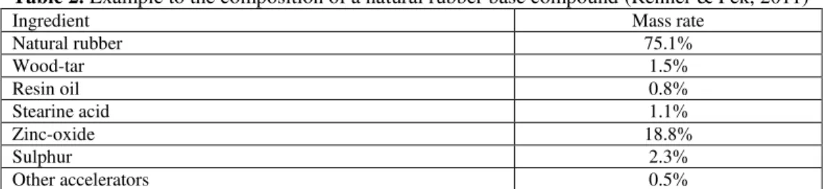
A compound base of natural rubber (Table 2.) has the following properties: (Renner and Pék, 2011):
High static tensile strength (15-22 MPa);
High elongation (600-900%);
Excellent elasticity at low temperature;
Poor ozone and degradation stability;
Good crafting because of excellent crude adhesion.
Table 2. Example to the composition of a natural rubber base compound (Renner & Pék, 2011)
Ingredient Mass rate
Natural rubber 75.1%
Wood-tar 1.5%
Resin oil 0.8%
Stearine acid 1.1%
Zinc-oxide 18.8%
Sulphur 2.3%
Other accelerators 0.5%
Table 3. Rubber % by Weight in New Radial Passenger (Evans, 2006)
Application/Component %
Tread 32.6%
Base 1.7%
Sidewall 21.9%
Bead Apex 5%
Bead Insulation 1.2%
Fabric/Fibre Insulation 11.8%
Steel Cord Insulation 9.5%
Liner 12.4%
Undercushion 3.9%
Total 100%
Table 4. SBR properties (S. Raja, 1990)
Excellent Good Poor
Abrasion resistance Tensile/elongation Ozone resistance
Water resistance Flex resistance Oil resistance
Cost Tear strength Solvent resistance
Compression set Resilience Fuel resistance
Low temperature High temperature (120 °C and
above) Synthetic rubber derive from the
polymerization of hydrocarbons, such as isoprene, butadiene and chloroprene (Gilliland, 1944). These and other monomers may be mixed in different parts, obtaining
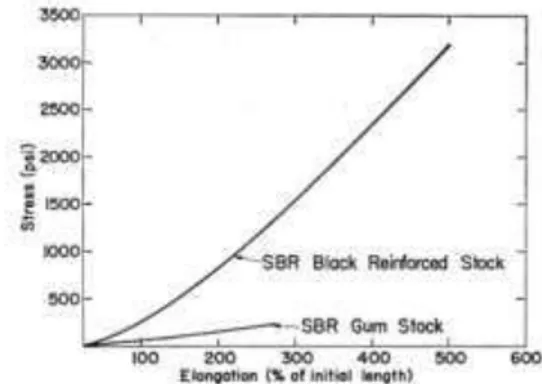
desired characteristics. Synthetic rubber, initially also known as "cold rubber", is better than natural rubber as far as tire tread is concerned (Society for Science & the Public, 1950). Another characteristic of the elastomers is the production of heat under stress. For modest elongations (about 200-300%) the work required for extension coincides almost completely with the entropy decrease and has as a consequence the production of heat. This production results from the random orientation of the chains of the elastomer (Campbell, 1963). Among the many synthetic kinds of rubber, it is certainly cited the SBR. Considered the greatest discovery in the field of elastomers, it is the most important rubber general purpose as well as the most produced worldwide (Niyogi, 2007a; Raja, 1990). In 1990, 40% of synthetic rubber used industrially was SBR, and the tire industry consumes most of the production of SBR. (Niyogi, 2007a; Raja, 1990). The International Institute of Synthetic Rubber (HSR) classifies SBR in six different series. Among its properties (Table 4), those which have most influenced success are the low cost, high abrasion resistance, which makes it ideal for passenger car tires, and a level of uniformity of the finished product comparable with that of natural rubber (Niyogi, 2007a). There are four main types of elastomer which are used in tires: Natural rubber, the already mentioned stirene-butadiene rubber (SBR), polystirene-butadiene rubber (BR) and butyl rubber (together with the halogenated butyl rubber). First three are used for the external parts of the tire, such as hip, shoulder and tread. Butyl rubber, impermeable against gases and air (Raja, 1990), is used in the liner. SBR is also used in liner's compound, because of its resistance to water and compression (Raja, 1990). In a modern car’s tire 15 or more rubber compounds are used (Lindenmuth, 2006). Carbon black: Material obtained from the incomplete combustion of heavy oil, such as tar or fossil tar obtained from ethylene cracking (Clarke, 2014a). It has a high
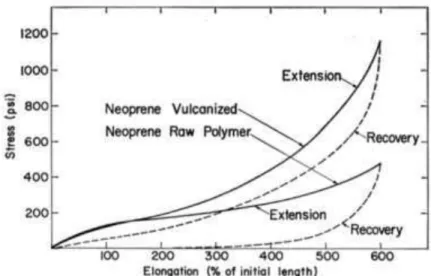
surface/volume ratio and contains a low percentage of PAH (polycyclic aromatic hydrocarbons). It is used both as a pigment and as a filler for reinforcement. It contributes to heat dissipation, thus increasing the life of the tire. As example, the effects of the addition of a 30% of carbon black to a SBR are reported in Figure 6. Carbon black is divisible into series, depending on the size of the particles. In the tire industry, the most used particles are comprised between 0.01 and 0.2 microns. (Clarke, 2014a). The percentage of carbon black in the tire compound varies depending on the manufacturer and type of tire. According to Downs et al., 1996, this percentage varies from 16 to 36%. A more recent study, Evans (2006), shows a percentage of about 22%, but also including silica. Due to its high density, carbon black may constitute more than 50% of the weight of compound (Campbell, 1963). The rubber industry accounts for 90-95% of world production of carbon black. Of these, 80% is used in the production of tires and related product (Niyogi, 2007b).
Figure 6. Vulcanized SBR with 30% carbon black compared with natural SBR
(Campbell, 1963)
to carbon black, but this gap was subsequently filled. The use of silica reduces fuel consumption by up to 2.6% and the overall environmental impact by 11%. According to Crump (2000), the silica has replaced 25% of the carbon black in tire compound.
Antiozonants: They are meant to stop or slow down the process of deterioration and cracking caused by exposure to ozone, an allotropic form of oxygen, that is contented in the atmosphere (Ozone damage testing, 2010). The ozone quickly causes the break of the unsaturated double bonds of rubber components (Niyogi, 2007b), such as aldehydes and ketones. This causes a reduction of the polymerization, which can lead to the formation of true cracks on the surface. A negative consequence is the rusting of metal components of the plies, in addition to the damage to the tire, due to humidity. Actually, the most effective antiozonant is para-phenylenediamines (Niyogi, 2007b).
Antioxidants: Waxy materials. They prevent oxidation, and thus the degradation of the tire caused by exposure to oxygen and ultraviolet rays. Oxygen acts more slowly than ozone, and carries a softening of natural rubber or a hardening in the case of SBR, and more generally to the progressive loss of physical properties. The process in this case can also from the air chamber, and from the liner spread outwards. Natural rubber contains natural antioxidants, while the synthetic rubber lacks of them. The use of synthetic rubber requires the addition of antioxidants (Bebb, 1976). Synthetic rubber such as butadiene-styrene and isoprene are very sensitive to oxidation. On the contrary, butyl rubber and ethylene-propylene-based rubbers in particular, are much less sensitive (Bebb, 1976). Principal antioxidants are amines, such as products of the reaction of diphenylamine, and phenolics (Niyogi, 2007b).
Plasticizers: They are elements that modify some properties of the compound to which
are added, such as malleability, flexibility, density, tensile strength or adhesiveness. Primarily are oils, softeners, or peptizers (Bebb, 1976). Called process oils in the rubber industry, they improve the mechanical performance of tires and properties at low temperatures. Plasticizers compose up to 30% of the compound.
Vulcanizing agents: During the
vulcanization process, they transform rubber from elastic into plastic material. Sulphur is the most common agent and is used for natural and many synthetic types of rubber (Niyogi, 2007b). In the case of some specific elastomers, metal oxides, difunctional compounds or peroxides are mixed as agents instead of sulphur (Niyogi, 2007b).
Accelerators: They accelerate the vulcanization process. In the absence of them, it would take 5 hours at 140 °C to complete the process (Niyogi, 2007b). The principal accelerators used in the vulcanization with sulphur are: Aldehyde – amines (also used as secondary plasticizer), Guanidines, Benzothiazoles, Sulfenamides, Dithocarbamates, Thiurams, Xanthates and Morpholines (Niyogi, 2007b).
Activators: They accelerate the vulcanization process by activating accelerators. The activators can be divided into inorganic and organic. Inorganic activators are: Zinc oxide, hydrated lime, litharge, red lead, white lead, magnesium oxide. The most common is zinc oxide. This is generally combined with a fatty acid, to form a soap-like compound in the rubber matrix. Organic are normally used in combination with inorganic. They are generally monobasic fatty acids or mixtures of the types, stearic, oleic, lauric, palmitic and myristic acids, and hydrogeneated oils from palm, castor, fish, and linseed oils (Niyogi, 2007b).
are organic acids such as salicylic acid and phthalic anhydrid (Niyogi, 2007b).
1.5. Reinforcement materials
As already mentioned, in tires and particularly in the carcass various reinforcing materials are used, especially textile fibers and metal wires:
Nylon: Mainly type 6 and 6,6. Nylon is strong and resistant to heat and moisture. It suffers from progressive elongation and flatspotting (Lindenmuth, 2006).
Polyester: Commonly Poly (ethylene succinate) (Koštial et al., 2012). Its characteristics are: high strength with low shrinkage, low service growth, low heat set and low cost. Compared to Nylon and Rayon, it is less resistant to heat (Lindenmuth, 2006).
Rayon: It is used primarily by European tire manufacturers and in some run-flat tires. It has good dimensional stability, heat resistance and it is easy to handle. By contrast, in addition to being expensive, it is sensitive to moisture (Lindenmuth, 2006). Aramid: It is 2 to 3 times stronger than polyester and nylon. It can be used as a light weight alternative to steel cord. Extremely strong and stiff, it is heat resistant. As well as expensive, it is difficult to cut (Lindenmuth, 2006).
Steel cords: Carbon steel wire coated with brass. The cables are twisted in multifilament strings. Strong and stiff, they require special manufacturing processes and are sensitive to moisture (Lindenmuth, 2006).
2.
Tire construction
2.1. Processing raw materials
The processing of the tire components is divided into two phases (Figure 7). In the first stage, raw materials such as plasticizers, carbon black and silica, normally held in
steel rollers. The compound is added through the opening between the two rollers, both above and below the fibers. The mix of the compound and the resulting fibers passes through other rollers up to obtain the mutual penetration and the desired thickness. During the process, parallel and spaced apart cotton yarns are also added to the plies. The function of these strands is to highlight the direction of the fibers. In addition, the cotton absorbs much moisture instead of plies, protecting them. The bead filler and the tread are produced by extrusion. The tread is devoid of notches, which will be etched in the moulding step. The steel belts are intertwined within the plant. The individual cables, formed from steel wires braided, are
clad in brass to promote the adhesion of the rubber. The density of the warp varies depending on the type of tire but must be constant. The obtained metallic fabric is combined with the compound again by calendering (Figure 9). Nylon belts are obtained by a single broad band of nylon, or with a wide waistband at most 8 mm, which during assembly is wound in a spiral around the tire. The bead wire is obtained by coiling the steel wires. The wires are copper-coated or brazed to enhance rubber adhesion (Koštial et al., 2012). The number of wires and of turns of winding depends on the size of the tire. Once impregnated with rubber, the spiral is firm. Welding is not necessary.
Figure 8. The open mixer, in which the compound, which came out from the Banbury mixer, is inserted [Courtesy of HSE]
2.2. Assembly and vulcanization
The various semi-finished products flow into the assembly zone. A packaging machine, that may be automatic or manual (Peled, 2015), is composed of two rollers. On the first roller liner, carcass, wires and sidewalls are assembled. On the second roller belts and tread are assembled. The two parts are assembled together and form the green tire (Shuy, 1964). The components are pressed together from the machine. An automated machine can assemble a tire in less than a minute. The tire is ready for the inspection may be subjected to curing. The vulcanization is a process in which the natural rubber binds with the sulphur. Ruber turns from a plastic into an elastic material (Clarke, 2014b). Also, as reported in Campbell (1963), the extension work, and consequently the production of heat under stress, is intensified (Figure 10). More generally, with the vulcanization is meant any chemical reaction that produces the same effect on synthetic rubber. This transformation occurs with the formation of cross-links (Clarke, 2014b), rare in nature or
absent in natural and synthetic rubbers, which are thermoplastic in nature. During vulcanization, normally hot performed, sulphur binds with various tire chains, creating cross-links. Vulcanization of rubber can be accomplished by different moulding techniques but according to Raja, 1990, the three most common are compression, transfer, and injection moulding. The vulcanization of the tire takes place in heated flat presses. Before insertion of the tire, the press is heated by steam at 180-200 °C. The press contains an air chamber. When the press is closed, the air chamber is inflated and presses the tire against the mould (Figure 11). The pressure can reach 22 bars. The moulding of a car tire lasts about 10 minutes that of a tire for transport read lasts about twice. The tire is then extracted for the inspection. The extraction of the tire from the mould is one of the most delicate moments of the process (Gavine, 2011). Tire mould release agent are used to facilitate the operation, normally sprayed on the green tire, on the mould or in the form of mould coating. The curing lasts from 1.5 to 16 hours (Degraeve et al., 1997).
Figure 11. Tire molding [Courtesy of Bridgestone]
2.3. Tire mould
Tire moulds are very complex and must be made with extremely tight tolerances. A mould is composed of several parts (Figure 12). Two elements called sidewall give shape to the tire sidewalls. The sidewall have the form of centrally perforated discs (a
“donut” shape, according to Chih-Hsing et al. (2013) and are made of steel. A number of elements, called segments, shape the tread
and are made of aluminum alloy. Segments’
grooves can be directly carved out by multi-axis CNC machining or the grooved segments can be made by precision casting (Chih-Hsing et al., 2013; Lecuiller, 2010). The grooving is a highly complex machining process and normally requires 5-axis CNC machining (Chih-Hsing et al., 2013). The price of a mould can be up to $ 60,000. It must be realized a mould for each type of tread and for each tire size. Due to economic reasons it is not possible to get a press for each mould. The change of the mould is a long operation. During the vulcanization the tire inflates inside the mould, adhering to it in all its parts. The air inside should then exit from the mould. Each plug is equipped with 2-3 channels, for a total of 1,500-2,000
channels, called “vents”, in a single mould.
They are divided into “vents” (1-2 mm) and
“microvents” (0.5-1 mm) (Young, 2000). These channels behave as small extrusion dies (Young, 2000). During the
vulcanization process are filled with the uncured rubber. Most of them remain attached to the tire once this has been
extracted, going to form the classic “hairs”
on the surface of the tires (Figure 13). This
“hairs” are called “vents”, too (Lindenmuth,
Figure 12. Tire mould [Courtesy of Tianyang Mold Co., Ltd]
Figure 13. Tire vents [Courtesy of Doug Chase]
Figure 14. Spring-vent [Courtesy of Gottschol Alcuilux CZ Ltd.]
This method is expensive and increases rubber waste. Trimming a single tire produces 40 g of rubber. Therefore, in a plant that produces 10 million tires a year, tire trimming produces 400 metric tons of extra waste (Spring vent technology, 2012). After 2010, the simple ventilation channels have been replaced by spring-vent (Figure 14). The spring-vent are little clips with the form of a screw, in number of 2-3 to gusset, which protude from the surface of the mould allowing the air outlet, but at full inflation range in coupling and prevent the compound from entering inside the duct. The spring-vent can be mounted both on new and on old moulds, both on steel and on aluminum moulds, with a price increase of 5-10% on the total cost of the mould (Spring vent technology, 2012).
2.4. Release agents
To facilitate the extraction of the tire, improve the quality of the tire and increase the wear resistance of the mould are used release agent, in form of coating or mixed together with the tire compound (Okada et al., 2014).
Single use release agents: Release agent are sprayed on mould. Principally are
non-reactive silicones, soap
solutions/suspensions and oils (Wolers). A certain amount of release agent remains attached to the tire, causing various problems.
Generally, the problems of this type of agent are the following (Wolers):
They require an extra step in the production process;
They can interfere with the compound flow in the mould, which may lead to poor knitting;
Depending on the type of material being used, they can cause mould fouling;
They contain VOCs that may be dispersed in the work environmentand cause health problems.
Semi-permanent release systems: These coatings are designed to release more tires with a single application. Technically the coating, in the form of film, reduces the adhesion of the rubber to the mould and the release agents do not remain on the surface of the tire, enabling to obtain a better moulding quality. Chemically, the film adheres to the mold due to Van der Waals’ forces (Wolers). The tread pattern and markings are better defined. This is important because the aesthetics of the tire is increasingly important in the competitive tire market (Gavine, 2011). The latest generation of semi-permanent release agent has additional features, such as increasing the number of tires that can be moulded before it is necessary to clean the mold. This reduces downtime. This result is obtained because the coating acts as a barrier, slowing the formation of fouling. (Gavine, 2011). Older types of semi-permament release agents are solvent-based, this causes problems of environmental impact and problems of health and safety at work. In some countries products containing these solvents have been banned. Solvents have been therefore replaced by other materials. Initially they were highly flammable products, that obviously caused new problems. However, safe products, with the same performance, were finally developed (Wolers).Permanent release agents: Commonly polytetrafluoroethylene, known by the trade name Teflon. The first permanent Teflon coatings appeared in the early 2000s (Young, 2002). The permanent coatings perform the same functions of semi-permament, mainly facilitate the extraction of the tire and slow down the formation of fouling.
Chrome (Cr), chromium nitride (CrN) and titanium nitride (TiN) are used for permanent and semi-permanent coatings (Okada et al., 2014).
2.5.
Tire markings
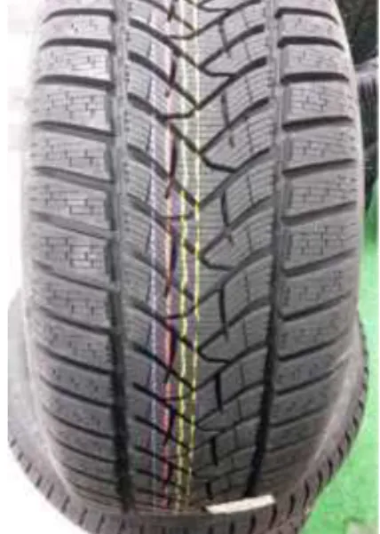
In the post-production phase, lines and colored points, that serve different functions, are plotted on the tires. On the surface of the tread of a new tire colored stripes and alphanumeric codes are visible. Such signs are printed on the tread when it is still in strip form, and used to identify the exact measure and model of tire to which such a tread is intended (Figure 15). On the sidewall of the tire, a red dot or a red and a yellow dots are marked (Figure 16). Together with a white dot marked on the rim, it is used in the match mounting. In Mavrigian (2008), it is explained that match mounting use to position the tire on the wheel in such a way that minimizes or deletes the final combination of radial force variation and/or imbalance. A red dot shows the tire radial, runout high point, while a yellow dot indicates the tire point of least weight, from a balance standpoint (Mavrigian, 2008). An employee usually performs the identification and quality control of the dots, but for the same task are being studied automated systems that use artificial vision (Dias et al., 2014).
3.
Tire moulds cleaning
3.1. Generalities
A tire mould is cleaned every 1,000-3,000 tires moulded (Schreiber, 2011). This number is the maximum limit to maintain an acceptable moulding quality. Above that limit, it is necessary to remove the mould fouling (Figure 17). They are mainly the result of the chemical reactions of sulphur and zinc oxide (Young, 2000). Furthermore, pieces of rubber often remain attached to the mould (Okada et al., 2014).
The reasons why it is important to keep clean a mould are:
To keep a proper surface finish of bead chaffer. This ensures proper adhesion of tire to wheel;
To make tire code clear and readable as required by law (Young, 2002);
To keep the logo and the name of the manufacturer of the tire clearly legible (Young, 2002);
To keep clean the vent or the spring-vent (Young, 2002);
To keep clean the contact surfaces between the sections of the mould, so there are no interruptions in tire surface and tread design (Young, 2002);
To ensure the coupling of the fields at high pressures;
To reduce the load on mechanical attacks of segments and other components (Young, 2002);
To avoid the formation of surface irregularities during the drying phase due to the problems previously listed;
To improve durability and reliability of the mould.
Generally, as the tire arrives at the moulding step, the majority of the cost associated with its production has already been spent. A tire that is damaged in this phase, for example because of a dirty mould, must therefore be discarded: This obviously has a high financial impact as a consequence (Young, 2000). For this reason, proper mould cleaning is fundamental. With technological progress, the amount of inorganic materials used in tires has increased. These materials may only be cleaned with acid products. This made obsolete the old alkaline washing machines, which were able to effectively clean only organic residues. The moulds do not have a single layer of dirt, but thousands layers, one for each tire moulded. Each layer is formed from an organic part and an inorganic part. Alkaline products can then remove only a certain number of layers of dirt. Beyond this number, the inorganic compounds form a barrier. For the same reason, you cannot clean a mould only with acid products, it would be stopped by organic dirt. Consequently, in the chemical cleaning are used alternately acid and alkaline products.
Figure 17. Tire mould partially cleaned. The brown part is still dirty [Courtesy of Clean
3.2. Cleaning technologies
Figure 18. Sandblasting of a sidewall [Courtesy of Eco Blast]
Figure 19. The two possible systems for blasting cleaning technologies (Foster, 2005)
Sandblasting: Cleaning systems by sandblasting are inexpensive, easy to install and maintain (Young, 2002). In the case of hand sandblasters, the operator should not have much experience. The sandblasting can only be done in closed environments, to prevent the spread of fine dust in the workplace and to easily recover abrasive materials used in cleaning (Young, 2002). In the cleaning of tire moulds cleaning
materials classified as “midly abrasive”,
such as glass, plastic, metal and ceramic, are used (Young, 2002). The particles impacting against the mould, due to the kinetic energy and the surface hardness, are fragmented. The fragments bouncing on the surface contribute to cleaning. The cleaning effect is therefore not limited to an impact per particle (Young, 2002). A sandblaster system
can be of two types: “Two-hose” or “single
-hose” (Figure 19). Basically, there is no
significant difference between the two configurations (Young, 2002). Even with methods "slightly abrasive", after a certain number of cleanings, the mould is too ruined and must be discarded. There are also other problems caused by these systems. Residues of abrasive material may be trapped and modify the surface of the mould. This can prevent proper adhesion of the chemical release agents that must bind to the metal surface (Young, 2002). If release agents do not come in contact with metal but with other materials, they cannot penetrate into the mould. Their action runs out in a number of cycles lower than those expected.
Figure 20. Hand dry ice blasting [Courtesy of Melbourne Dry Ice Blasting]
Dry ice blasting: This system consists of a hand or automatic gun that shoots dry ice against the mould (Figure 20). The dry ice is fired at a temperature of -78.5 °C against the mould at a temperature of 180/200 °C. The temperature difference vaporize the dry ice before it touches the surface of the mould (Foster, 2005). The shock waves generated by these explosions easily removed the fouling. The dry ice blasting can also be used on moulds at room temperature. Cleaning of
“hot” mould is 3-4 times faster than cleaning
of “cold” mould (Young, 2002). In particular, below 65 °C, the fouling is no longer a glass-like material, easy to crumble, but it becomes a very dense visco-elastic material that absorbs the impact energy of CO2 explosion (Young, 2002). The impact
machine with rotating blades a standard 60 lb (27 kg) dry-ice block (Foster, 2005; Young, 2002). The flakes have a low density and do not guarantee high level of cleanliness (Foster, 2005). For maximum impact energy are used pellets of high density, obtained by extrusion and cutting of a string of dry ice. Pellets are available in several sizes ranging from 1 mm to 3 mm in diameter (Foster, 2005). As for the sandblasting, there are two types of dry ice blasting systems: “Two-hose” or “
single-hose” (Figure 19). However, on the contrary of the sandblasting, there is a big difference between the two systems (Young, 2002). In single-hose system, the exhaust Mach number of particles is about 1.0-3.0. While, in two-hose system the exhaust Mach number is only slightly supersonic (Foster, 2005). The single-hose systems, due to the increased exhaust speed of the particles, are more efficient. Dry ice blasting is not capable of eroding the surface of the mould (Young, 2002). The automatic cleaning dry ice blasting can be carried on board, and without removing the mould from the press. In this way, they reduce downtime and avoids the formation of a flow of secondary waste (Foster, 2005; Young, 2002). A dry ice blasting can clean vent very small, up to about .03 inch, or 0.7 mm (Young, 2002). The extreme noise is among the critical points. In the case of hand dry ice blasting, there may be laws that protect the operator from loud noises (Young, 2002). The dry ice blasting can cause dusty conditions. Vacuum systems are required. This technology began to spread among all the large tire manufacturers from the mid-80s (Young, 2002).
Laser cleaning: Cleaning technology that uses high power laser, up to 10 MW (Schreiber, 2011), to break down fouling. The affected area is equal to the size of the laser beam (Schreiber, 2011). The mould partially absorbs the laser. The substrate of the mould does not suffer mechanical stress, chemical stress or heat stress (Schreiber, 2011). Laser cleaning can be used on board,
using 5-axis robot. It may also be used off board, both on high temperature moulds than on room temperature mould. Furthermore, the laser does not generate secondary waste (Gavine, 2011) and do not have residual powder on the surface. Compared to dry ice blasting, it has less environmental impact, with lower energy consumption, lower production of CO2 and minimum noise
pollution. The cost of a single cleaning operation is about 3 euros, compared to 20 € of dry ice blasting (Schreiber, 2011). The investments required are high, 2-3 times higher than those required by an on-board robotic dry ice blasting, 25-30 times higher than a hand dry ice blasting. A problem of cleaning laser is its difficulty to clean vent or very small cavity, in particular it is problematic to clean tread with complex designs (Young, 2002). Laser technology does not allow a high level of cleanliness in the case of moulds with spring-vent that are not cleaned by the laser beam. Indeed, the high temperature of the laser carbonize any residue of oil and this blocks the spring-vent.
Figure 21. Automatic laser cleaning [Courtesy of 4JET Technologies GmbH]
Figure 22. Operating principle of ultrasonic cavitation [Courtesy of Ultrawaves GmbH]
Ultrasonic cleaning: Technology that uses ultrasonic sound waves whose frequency is higher than the audible to the human ear. Conventionally, ultrasounds are sound waves with a frequency above 20 kHz. Ultrasonic cleaning technology is fairly old, it is used industrially since the 50s and has become economically viable since the 70s. It is used to wash small metal parts such as jewelry, lenses, optical parts, watches, coins. It serves mainly to wash away polishing pastes, which are a mixture of organic and inorganic components. The ultrasonic cleaning is also used on dental instruments, surgical instruments, tools, weapons, electronic components, circuit boards and moulds. Specifically, ultrasound is used to create the phenomenon of cavitation. The cavitation is the formation, growth and collapse of micron-sized bubbles, resulting in the release of enormous energy (Figure 22). The temperature can exceed 5000 °C and pressure of 700 N/cm2 (Johnson, 2007). These shock waves break the fouling. The phenomenon is the same that is on propellers and pump impellers, which are destroyed if made to work at excessive speed. Ultrasound ranging from 20 to 100 kHz is used in industry as it has the ability to cause cavitation (Pilli et al., 2011; Rastogi 2011).
surface finishing, it has an incubation period of erosion of more than 30 hours
(D’Oliveira, 2003), well above the few minutes needed to cleaning. To ensure the highest quality of cleaning, ultrasound is used in combination with high temperature
and chemical attack (Bignozzi et al., 2016). Typically used are acid agents and alkaline agents, for the reasons previously treated (Figure 23). Ultrasonic cleaning is the only technology that is able to clean the spring-vent.
Figure 23. Example of Injection Mould Ultrasonic Cleaning Machine with a multi stage treatment (Courtesy of Keymical)
4.
Conclusions
The increased performance of the cars, increasing demands of high performance and security and, especially in recent years, the demand of a better external appearance fuel efficiency, have led to a constant evolution of the tires in terms of material, construction and tread design. The majority-required quality has also led to an evolution in the field of tire moulds, in particular with the adoption of the spring-vents. Ultimately, this has caused the demand for more efficient mould cleaning systems. The extensive use
of inorganic elements in the compound made obsolete alkaline washing machine, and has made necessary the development of innovative cleaning system, which are the dry ice and laser. The adoption of the spring-vents has led to the recovery of an old cleaning technology, that is the ultrasonic cleaning. It permits to obtain a very high level of quality finishing (Figure 24), together with several other useful benefits at the level of process and products.
Figure 24. Comparing tire surfaces before and after the Injection Mould Ultrasonic Cleaning (Courtesy of Keymical)
Table 5.
Overview of tire mould cleaning technologies
Technology Mould
erosion
Clean level
Spring-vent cleaning
On board cleaning
Man Power
Needs
Clean Speed H&S
Final Score
Automatic
sandblasting YES High NO NO NO < 2H Good 4
Hand
sandblasting YES High NO NO YES > 2H Good 2
Automatic dry
ice NO High NO YES NO < 2H Good 6
Hand dry ice NO High NO NO YES > 2H Good 3
Laser NO Medium NO YES NO < 2H Good 5.5
Alkaline
washing NO Low NO NO NO > 2H Poor 2.1
Ultrasonic NO High YES NO NO < 2H Good 6
References:
Adewuyi, Y. (2001). Sonochemistry: environmental science and engineering applications. Ind. Eng. Chem. Res., 40(22), 4681-4715. doi: 10.1021/ie010096l
Bebb, R. (1976). Chemistry of Rubber Processing and Disposal. Environmental Health Perspectives, 17, 95-102. Retrieved from: http://www.jstor.org/stable/3428613
Bignozzi, M.C., Saccani, A., & Fragassa, C. (2015). Experimental Evaluation of the Surface Alteration of Gasket Samples under Operative Conditions. Tribology in Industry, 37(4), 482-490.
Campbell, J. (1963). Synthetic Elastomers. Science, 141(3578), 329-334. Retrieved from: http://www.jstor.org/stable/1710842
Chih-Hsing, C., & Chih-Hsin, H. (2013). Precise 5-axis grooving of tire mold based on Surface re-parameterization. International Journal of Precision Engineering and Manufacturing, 14(10), 1811-1816. doi: 10.1007/s12541-013-0242-4
Clarke, M. (2014a). It is easy to say rubber. Pneurama, 4.
Clarke, M. (2014b). The importance of vulcanization. Pneurama, 5.
Crump, E.L. (2000). Economic Impact Analysis for the Proposed Carbon Black Manufacturing NESHAP (EPA-452/D-00-003). Washington D.C.: US Environmental Protection Agency.
D’Oliveira, A. (2003). Phase transformation during cavitation erosion of a Co stainless steel.
Materials Science and Engineering: A, 10. doi: 10.1016/S0921-5093(03)00297-1
Degraeve, Z., & Schrage, L. (1997). A Tire Production Scheduling System for Bridgestone/Firestone Off-The-Road. Operations Research, 45(6), 789-796. Retrieved from: http://www.jstor.org/stable/172064
Dias, A.P., Silva, M.F., Lima, N., & Guede, R. (2014). Identification of marks on tires using artificial vision for quality control. International Journal for Quality Research, 9(1), 27-36. Downs, L.A., Humphrey, D.N., Katz, L.E. & Rock, C.A. (1996). Water quality effects of using
tire chips below the groundwater table. Orono, Maine: Department of civil and environmental engineering.
Drury, D. J. (2013). Formic Acid. In Kirk-Othmer (Ed.), Kirk-Othmer Encyclopedia of Chemical Technology.
Dunlop, J.B. (1888). British Patent No. 10,607. London: H.M. Stationery Office
Eberhart, J. (1965). New Rubber for New Tires. The Science News-Letter, 87(12), 179. Retrieved from: http://www.jstor.org/stable/3948849
Evans, A., & Evans, R. (2006). The Composition of a Tyre: Typical Components. England, Banbury: The Waste & Resources Action Programme
Foster, R.W. (2005). Carbon Dioxide (Dry-Ice) Blasting. In SSPC (Ed.), Good Painting Practice: SSPC Painting Manual, 1(4), 161-167.
Fragassa, C., Pavlovic, A., & Massimo, S. (2014). Using a Total Quality Strategy in a new Practical Approach for Improving the Product Reliability in Automotive Industry: International Journal for Quality Research, 8(3), 297–310. ISSN 1800-6450.
Gavine, A. (2011). Free Time. Tire Technology International, 4, 26.
Gilliland, E. (1944). Synthetic Rubber. The Scientific Monthly, 58(1), 5-15. Retrieved from: http://www.jstor.org/stable/18135
Gorenstein, S. (1970). Planning Tire Production. Management Science, 17(2), B72-B82. Retrieved from: http://www.jstor.org/stable/2629216
Gough, V. (1981). Structure of the pneumatic tire. In U.S. Department of Transportation, National Highway Traffic Safety Administration (Ed.), Mechanics of Pneumatic Tires, 203-248.
Johnson, S. (2007). Cleaning Moulds, Part III Ultrasonics Make Life Easier. Plastics Technology, 9.
Kerkstra, R. (2016). Designing Molds for Easy Cleaning & Maintenance in the Press. Plastics Technology, 1.
Lecuiller, A. (2010). Tire mold issues. Tire Technology International, 7, 12.
Lindenmuth, B.E. (2006). An overview of tire technology. In U.S. Department of Transportation (Ed.), The Pneumatic Tire, 2-27.
Mangili, I., Lasagni, M., Anzano, M. et al. (2015). Mechanical and rheological properties of natural rubber compounds containing devulcanized ground tire rubber from several methods. Polymer Degradation and Stability, 121, 369-377. doi:10.1016/j.polymdegradstab.2015.10.004
Mark, H. (1943). Some scientific aspects of the synthetic rubber problem. American Scientist, 31 (2), 97-141. Retrieved from: http://www.jstor.org/stable/27825983
Mavrigian, M. (2008). Tire match mounting & custom wheel handling. Motor, 4, 38-47. Nyogi, U.K. (2007a). Natural and Synthetic Rubber. Retrieved from:
http://nsdl.niscair.res.in/jspui/bitstream/123456789/380/1/Revised%20Natural%20and%20S ynthetic%20Rubber.pdf
Nyogi, U.K. (2007b). Additives for Rubbers. Retrieved from: http://nsdl.niscair.res.in/jspui/bitstream/123456789/382/2/revised%20additives%20for%20ru bber.pdf
Okada, A., Okamoto, Y., Clare, A. & Uno, Y. (2014). Fundamental study on releasability of molded rubber from mold tool surface. The International Journal of Advanced Manufacturing Technology, 70(5), 1515-1521. doi:10.1007/s00170-013-5415-x
Ozone damage testing (2010). Tire Technology International, 7(6).
Peled, J. (2015). Future tyre production: principles and methods. Kauchuk i Rezina, 2, 22–25. Pilli, S., Bhunia, P., Yan, S., LeBlanc, R. & Tyagi, R. (2011). Ultrasonic pretreatment of
sludge: a review. Ultrason Sonochemistry, 18(1), 1-18. doi:10.1016/j.ultsonch.2010.02.014 Raja, K.S. (1999). Rubber Processing: Rubber History, Factors Influencing Moulding, Mould
Design Studies (Master thesis), California State University, California.
Renner, T., & Pék, L. (2011). Comparing Strength Properties of Natural And Synthetic Rubber Mixtures. Sustainable Construction and Design, 2(1), 134.
Ridha, R. (1974). Analysis for Tire Mould Design. Tire Science and Technology, 2(3), 195-210. doi: 10.2346/1.2167186
Rodgers, B. (2015). Rubber Compounding: Chemistry and Applications, Second Edition. Boca Raton, FL: CRC Press.
Savage, A.J. (1915). U.S. Patent No. 1,203,910. Washington, DC: U.S. Patent and Trademark Office
Schreiber, F. (2011). More Than Clean - Laser Cleaning of Tire Molds. 4SURfaces, 2, 12-13. Shuy, R. (1964). Tireworker Terms. American Speech, 39(4), 268-277. Retrieved from:
http://www.jstor.org/stable/454322
Society for Science & the Public (1950). Cold Rubber Is Superior to Natural in Tire Treads. The Science News-Letter, 57(7), 103. Retrieved from: http://www.jstor.org/stable/3927492 Solo, R. (1954). Research and Development in the Synthetic Rubber Industry. The Quarterly
Journal of Economic, 68(1), 61-82. Retrieved from: http://www.jstor.org/stable/1881918 Spring vent technology (2012). Tire Technology International, 4(54).
Thomas, B.S., Gupta, R.C., & Panicker, V.J. (2016). Recycling of waste tire rubber as aggregate in concrete: durability-related performance. Journal of Cleaner Production, Elsevier. Retrieved from: http://www.sciencedirect.com/science/article/pii/ S0959652615011361
Thomson, R.W. (1847). U.S. Patent No. 5,104. Washington, DC: U.S. Patent and Trademark Office.
U.S. Customs and Border Protection (2014). What Every Member of the Trade Community Should Know About: Tires. Retrieved from: https://www.cbp.gov/sites/default/ files/documents/Classification-of-Tires-ICP-April-2014_0.pdf
Wolers, M.E. (n.d.). Waterbased Release Systems for a safe Environment and Workplace. Retrieved from: http://www.performance-additives.com/PDFs/Waterbased release systems I.pdf
Young, F.C. (2000). Blast Off. Tire Technology International Magazine, 12, 54-58.
Young, F.C. (2002). Removing fouling residue from molds in-the-press with CO2 pellet blasting. Rubber World, 227(3).
Cristiano Fragassa University of Bologna, Department of Industrial Engineering
Forlì Italy
Martin Ippoliti University of Bologna, Department of Industrial Engineering
![Figure 2. Schematic structure of a radial tire [Courtesy of Wikimedia Commons]](https://thumb-eu.123doks.com/thumbv2/123dok_br/18196941.333021/2.808.418.669.562.743/figure-schematic-structure-radial-tire-courtesy-wikimedia-commons.webp)
![Figure 7. Schematic representation of the production process of a tire [Courtesy of WBCSD]](https://thumb-eu.123doks.com/thumbv2/123dok_br/18196941.333021/9.808.115.676.447.927/figure-schematic-representation-production-process-tire-courtesy-wbcsd.webp)
![Figure 9. Calendering of plies [Courtesy of HSE]](https://thumb-eu.123doks.com/thumbv2/123dok_br/18196941.333021/10.808.262.526.498.897/figure-calendering-plies-courtesy-hse.webp)
![Figure 11. Tire molding [Courtesy of Bridgestone]](https://thumb-eu.123doks.com/thumbv2/123dok_br/18196941.333021/12.808.124.376.118.369/figure-tire-molding-courtesy-bridgestone.webp)
![Figure 12. Tire mould [Courtesy of Tianyang Mold Co., Ltd]](https://thumb-eu.123doks.com/thumbv2/123dok_br/18196941.333021/13.808.107.379.368.730/figure-tire-mould-courtesy-tianyang-mold.webp)