DOI: 10.13164/re.2015.0171 SIGNALS
Fast Implementation of Transmit Beamforming
for Colocated MIMO Radar
Gollakota Venkata Krishna SHARMA
1, Konduri RAJA RAJESWARI
21
Dept. of ECE, GITAM Institute of Technology, GITAM University, India
2
Dept. of ECE, College of Engineering Autonomous, Andhra University, India [email protected], [email protected]
Abstract. Multiple-input Multiple-output (MIMO) radars benefit from spatial and waveform diversities to improve the performance potential. Phased array radars transmit scaled versions of a single waveform thereby limiting the transmit degrees of freedom to one. However MIMO ra-dars transmit diverse waveforms from different transmit array elements thereby increasing the degrees of freedom to form flexible transmit beampatterns. The transmit beam-pattern of a colocated MIMO radar depends on the zero-lag correlation matrix of different transmit waveforms. Many solutions have been developed for designing the signal correlation matrix to achieve a desired transmit beampattern based on optimization algorithms in the liter-ature. In this paper, a fast algorithm for designing the correlation matrix of the transmit waveforms is developed that allows the next generation radars to form flexible beampatterns in real-time. An efficient method for sidelobe control with negligible increase in mainlobe width is also presented.
Keywords
Multiple-input multiple-output radar, transmit beam-forming, fast implementation, waveform diversity, zero-lag correlation matrix
1.
Introduction
MIMO radars employ multiple transmit antennas and multiple receive antennas thereby benefiting from in-creased degrees of freedom due to spatial diversity. These radars further have the flexibility to transmit diverse wave-forms from their different transmit antennas thereby bene-fiting from waveform diversity. This spatial diversity and waveform diversity together can be used to improve many aspects of radar system performance [1]. MIMO configu-rations employing widely separated antennas [2] called
“Statistical MIMO” radars improve target detection capa -bilities due to spatial diversity. MIMO radars can also
employ closely spaced antennas [3] called “Colocated MIMO” radars to improve interference rejection capability, parameter identifiability and resolution performance due to
increased virtual aperture. In this paper we deal with colo-cated MIMO radar only.
Conventionally MIMO radars employ orthogonal sig-nals to obtain the phase delay for each transmitting/receiv-ing antenna pair, thus increastransmitting/receiv-ing the degrees of freedom for beamforming. However MIMO radars can also employ partially correlated signals to form flexible transmit patterns with better performance than phased array beam-patterns for a given number of transmit antenna elements. The advantages of MIMO radars (employing diverse wave-forms) in forming flexible transmit beampaterns over phased array counterparts are well illustrated in [4]. While phased arrays employ only spatial diversity to form trans-mit beams, MIMO radars employ both spatial and wave-form diversity to wave-form transmit beams with enhanced flexi-bility.
The transmit beampattern of a colocated MIMO radar depends on the zero-lag correlation matrix of different transmit waveforms [5–6]. Orthogonal transmit waveforms result in uniform illumination of power in all directions which is very helpful in search applications. Fully corre-lated waveforms (perhaps also scaled by a complex con-stant) result in directive beams used in tracking applica-tions. Partially correlated waveforms with a specific zero-lag correlation matrix can be used to form a wide range of beampatterns.
correlation matrix for designing different transmit beam-patterns along with minimization of crossbeam pattern is formulated as an SDP optimization problem and solved using an efficient cyclic algorithm proposed therein. In [7], an eigenvalue decomposition method is used to achieve specific illumination pattern. Many target tracking applica-tions require flexible transmit beampatterns generated in real-time. Previous works on signal correlation matrix design for approximation of desired transmit beampatterns employed optimization methods which are difficult to solve in real-time or highly complex to implement in hardware.
This paper considers the real-time computation of the zero-lag signal correlation matrix R that approximates a desired beampattern. The main contributions of this paper are (a) closed-form solution for computing the zero-lag correlation matrix and (b) FFT based algorithm for compu-ting the zero-lag correlation matrix. The advantage of the proposed algorithm is that the proposed algorithm is easily amenable to hardware implementation since efficient architectures for FFT algorithms exist [18].
Section 2 describes MIMO radar signal model and de-fines a complete beampattern that includes the specification of transmit and cross beampattern. Section 3 derives the closed form solution and presents a fast implementation of the solution using 2D FFT algorithm. Section 4 presents the numerical results and Section 5 concludes the paper.
2.
MIMO Radar Signal Model
Consider a monostatic MIMO radar that contains M transmitters with the antenna elements configured as uni-form linear arrays. We assume a point target and also that the target and transmitters lie in the same 2-D plane as shown in Fig. 1. Let dT represent the spacing between
con-secutive transmitters. Let θ be the target angle with respect to the broadside direction and O is the carrier wavelength of the transmitted waveforms. Let {um(t)}, m {0,1,…,M– 1} represent the ܯ transmitter waveforms. All the transmit antennas transmit waveforms simultaneously in time. We further assume that the transmitter waveforms are narrow-band and the basenarrow-band signal waveforms are not modified because of Doppler effect [15]. The correlation between two transmit waveforms um(t) andum’(t) at zero time-lag is
defined as
0
* ,
0
T
m m m m
r c
³
u t u c t dt (1)and R = [rm,m’]M × M represents the zero-lag correlation matrix of the M transmit waveforms.
2.1
Transmit Beampattern
The baseband signal at the target location can be described by the expression
1 2
0
M
j fm H
m m
e S u t f t
¦
aHHH ff u (2)Fig. 1. Transmitter model.
where f dTsin T O/ is the spatial frequency of the target,
0 1 2 1
T M
t ª¬u t u t u t }u t º¼
u (3)
is the vector of M transmit waveforms and a(f) is the array steering vector given by
2 1
2 .0 2 .1 j f M T
j f f
f ¬ªe S e S e S º¼
a eeejj2 ff . (4)
With typical transmitter spacing of dT = O/2, the spatial
frequency f is in [–½, ½]. The spatial distribution of power of the transmit signals is called the transmit beampattern and is given by [4],
[ H H ] H
P f E a f u t u t a f a f Ra f
1 1 2 , 0 0
M M
j f m m m m
m m
r ce S c
c
¦¦
. (5)Consider P(f) for a phased array radar case. The M × 1 transmit signal vector u(t) is given by
u(t) = a(f0) u(t) where f0 = dT sin(θ0)/O with θ0 denoting the
steered direction. Then, R = a(f0) aH(f0) assuming unit
power signal u(t) and
2
0 0 0
P f aH f a f aH f aH f aH f a f .
(6)
Note that the transmit gain attains maximum value in the direction θ0and is decreased at θzθ0Ǥ Now, consider
P(f) with orthogonal signals. Then, R = I, and
P f aH f a f M (7)
this implies that the beampattern is omnidirectional. Thus, the traditional beamforming results in a focused beampat-tern while the beampatbeampat-tern of MIMO with orthogonal sig-nals is uniform in all directions. In some applications, it might be desirable to synthesize a beampattern that is be-tween these two extremes so that wide focus areas can be formed without wasting power in the directions that are of no interest. This can be achieved by adjusting the correla-tion matrix Rof the transmitted waveforms.
2.2
Crossbeampattern
H H
c f fc E aª¬ f u t u t a fc ¼º a f Ra fc
1 1 2 , 0 0 , M M
j fm f m m m
m m
r ce S c c f f
c
z c
¦¦
(8)In practical applications, it is desirable to minimize c(f, f’) for improving the quality of adaptive localization techniques [16]. In phased array beamforming, the signals backscattered to the radar from two targets (at location parameters f and f’) are fully coherent, which in particular makes the adaptive localization techniques inapplicable [16].
2.3
Complete Beampattern
The complete beampattern s(f, f’) as a function of spatial frequencies f and f’ can be written as
1 1 2
, 0 0
,
M M
j fm f m H
m m m m
s f f f f r ce S c c
c
c a Ra c
¦¦
(9)We note that transmit beampattern P(f) is the com-plete beampattern evaluated along the f = f’ line i.e., P(f) = s(f, f ). The crossbeampattern c(f, f’) is the complete beampattern s(f, f’) at f z f’Ǥ From (9), we see that the complete beampattern is the scaled two-dimensional Fou-rier transform of the zero-lag correlation matrix R. We also notice that with typical transmitter spacing dT = O/2, s(f, f’)
is periodic w. r. t f, f’ with period 1.
2.4
Problem Formulation
The objective in transmit beampattern design, is to design R so that the transmit power is directed in desired directions f and c(f, f’) is minimized. The specification of complete beampattern s(f, f’) (rather than just the transmit beampattern P(f) captures both these goals. We state the design problem as follows: Given a desired beampattern function sd(f, f’), find the matrix R = [rm,m’]M × M that closely approximates the relation
1 1 2, 0 0
,
M M
j fm f m
d m m
m m
s
f f
r
e
S
c c c
c
c
¦¦
. (10)Any practically achievable signal correlation matrix R
will be positive semi-definite and Hermitian (i.e. rm,m’ = r*m,m’). R will have the property if we choose the
desired beampattern function sd(f, f’) that is real valued and symmetric about the f = f’ line. Further the total transmit energy can be constrained to P by multiplying R
by the factor P/tr{R}.
3.
Closed Form Solution
We now proceed to derive a closed form solution to design the correlation matrix R to realize the desired complete beampattern sd(f, f’) given by
1 1 2, 0 0
,
M M
j fm f m
d m m
m m
s f f r e S
c c c
c
c
¦¦
. (11)Multiplying (11) on both sides by ej2Sfk1ej2S cf k2 and
integrating w.r.t f and f’ over one period (0,1) we have
1 2 1 2 1 1 2 2 0 01 1 1 1
2 2 , 0 0 0 0 , .
j fk j f k d
M M
j f m k j f m k m m
m m
s f f e e dfdf
r e e dfdf
S S S S c c c c c c c c
³³
¦¦
³³
(12)Interchanging the order of integration and summation we have
1 2
1 1
1 1
2 2
, 1 2
0 0 0 0
,
M M
j f m k j f m k m m
m m
r e S df e S df r k k
c c c c § ·§ · ¨ ¸¨ ¸
© ¹© c¹
¦¦
³
³
(13)
In the above equation, the relation 1 2
0
j f n k
e S df G nk
³
has been used. The closed form solution for the zero-lag correlation matrix R = [rm,m’]M × M is given by
' 1 1 2 , 0 0, j fm f m d
m m
r
³³
s f fc e S c cdfdfc. (14)A similar solution is presented in [17]. However the difficulty is in the evaluation of the integral in (14). In mission critical target tracking applications, computation of
R from (14) is not possible in real-time. This problem is analogous to FIR filter design using Fourier series method wherein the desired unit sample response hd (n) of the FIR filter to the designed one is calculated from the desired frequency response Hd (ejω) as [18].
1 2
j j n
d d
h n H e e d
S
Z Z
S
Z
S
³
. (15)An approximation to hd (n) can be obtained by sam-pling Hd (ejω) and using the inverse discrete Fourier trans-form to compute
1
2 / 2 /
0
1
K
j K k j N kn
d d
k
h n H e e
K S S
¦
1 dh nd 1
K ,
0d dn N1 (16)
where N is the length of the FIR filter. If K >> N, hhddd
nncan be expected to be a good approximation to hd (n). In a similar way, the integral in (14) can be approximated as
1 1 2 –
,
0 0
1 1
,
km k m
K K j
K K
m m d
k k
k k
r s e
K K K K
S§ ·
¨ ¸
© ¹
c
c c
c
§ c·
¨ ¸
© ¹
¦¦
,
1 1
m m, rm m
K K
0dmdM1, 0dmcdM1. (17) If K >> M, rrm,m’ can be expected to be a good
using 2-D inverse fast Fourier transform (FFT). This allows the correlation matrix to be computed in real-time in con-trast to previously proposed optimization based methods. The steps of the algorithm are presented below
1. Given the desired complete beampattern function
sd (f, f’)(specified over a large grid of points over f and
f‘ ) ass k kˆd
, ,c sdf fcat , , k k f fK K
§ ·
¨ ¸ ©
c ¹ c
withk k, {0,1c ,.., K1)whereK >> M. Typically
K = 3M is adequate.
2. Find the 2-D inverse fast Fourier transform of sˆd
k kc,to obtain Ŝd (m, m').
3. The desired correlation matrix can be obtained
asrm m, c Sˆd
, m M mc over0dm m, cdM1.Here ()M indicates modulo M operation.
In Step 3 above, the reflection property of 2-D Fourier transform viz. If x(n1, n2) →X(ω1, ω2) then x(n1, –n2)
→X(ω1, –ω2), is used.
4.
Design Results
Two scenarios are considered for the simulation. The first scenario considers the maximum power design at known target locations and the second scenario considers beampattern matching design.
4.1
Maximum Power Design for Known
Target Locations
In practice, to obtain the prior knowledge about the target locations, orthogonal waveforms [19], 20] are used for MIMO probing. This is referred to as “initialprobing”. After we get the target location estimates with this probing and spatial spectrum estimation techniques [21], we can optimize the transmitted beampattern to direct the transmit power in these known target locations. We define a simple parameterized expression for the desired beampattern function. Assume that there are K targets in the range of the radar, located at angles θk, corresponding to spatial fre-quencies { fk }, k = 0,1, …,K – 1 with fk= dT sin(θk)/O. We would like to concentrate the energy in the vicinity of each target. The desired beampattern sd (f, f’) is expressed as
,1
, , * ,
K
d d k
k
s f fc
¦
s f fc g f fc (18)where
,
1 ,
0 otherwise
k d k
f f f
s f fc ® c
¯
22
22 22
1 1 2
, .exp
2 1
1 x x y y
x y
f ff f
g f f
f f f f
f f
U U
U
ª º½
° °
« »
® ¾
°¯ «¬ »°
c c
c
¼¿
(19)
and * represents convolution.
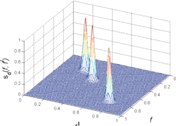
The function g(f, f’) is used to reduce the sidelobe level in the resulting beampattern by providing smooth tapering on all sides. When fx = fy and 0 < U < 1 the contour of g(f, f’) reduces to an ellipse rotated by angle π/4 i.e. along the line f= f’. This choice makes sd (f, f’) symmetric along the f= f’ line, resulting in a zero-lag correlation matrix R that is positive semi-definite and Hermitian. The choice of U affects the resolution along the f= f’ line and fz f’ directions. The choice of U = 0 and U = 1 makes the contour of desired beampattern a circle and ellipse respec-tively at each desired direction along the f= f’ line. The function in (19) provides more degrees of freedom to con-trol sidelobe levels compared to a tapering window ap-proach used in [11]. The values fx, fy can be increased so that energy in Ŝd(m, m')can be spread uniformly along m,m’ǡ so that rm,m | constant thus satisfying the uniform elemental power constraint [4]. As an example, the desired beampattern function for three targets located at f0 = 0.25,
f1 = 0.4 and f2 = 0.75 is shown in Fig. 2. The other
parame-ters are chosen as fx =fy =0.02 and U = 0.2.
The 2-D inverse FFT coefficients Ŝd(m, m') of the desired beampattern function are shown in Fig. 3. We see that most of the energy is contained in the coefficients with 0 dm d 15 and 0 dm’ d 15.
The beampattern obtained for different values of M is shown in Fig. 4. Note that M = 5 does not provide enough degrees of freedom for synthesizing three distinct beams. We also note that M = 20 does not offer distinct advantages over M = 15. The transmit beampattern for different values of M is shown in Fig. 5.
One of the practically motivated constraint is to have the transmit waveforms with uniform elemental power constraint to limit the transmit signals having wildly vary-ing magnitudes thereby limitvary-ing signal distortion. The diagonal elements of the computed correlation matrix rep-resent the power of the transmit signals emitted by various transmitters. With U = 0.4, the spread of the energy in the resulting correlation matrix R, is evenly distributed result-ing in a maximum to minimum element ratio of 1.2 thus nearly satisfying the uniform elemental power constraint.
Fig. 3. 2-D inverse FFT coefficients Ŝd (m, m') of the desired
beampattern function.
Fig. 4. Beampattern function with M =5, 10, 15 and 20.
Fig. 5. Transmit beampattern with M =5, 10, 15 and 20.
Fig. 6. Transmit beampattern evaluated using the algorithm in [4] and the proposed algorithm.
For comparison, the correlation matrices ܀ and܀ for achieving maximum power at spatial frequencies
f1 = 0.2 and f2 = 0.4 are computed using (i) convex
optimi-zation method proposed in [4], and (ii) the proposed FFT based algorithm. The other parameters are chosen as M = 15, fx =fy =0.02 and U = 0.2. The transmit beampattern of corresponding correlation matrices is plotted in Fig. 6. It can be noticed that the proposed algorithm achieves the low sidelobe levels with small increase in mainlobe width.
4.2
Beampattern Matching Design
Consider a desired beampattern߶ሺߠሻ given by
>
, ,@
1, 2, ,0 otherwise
k k k k k k K
P T T T
I T ® ' ' }
¯
(20)
with K = 3, θ1 = –30°, θ2 = 0°, θ3 = 40°, Δk= 10°, μ1 = 0.5,
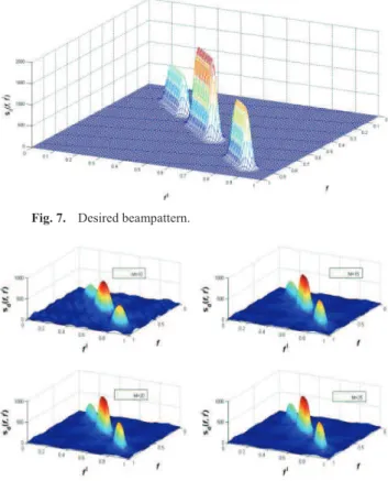
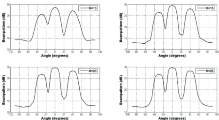
μ2 = 1, and μ3 = 0.75. Here θk represents the location of the kth target. Δk, μk represent the beamwidth and transmit gain in the direction of the kth target respectively. The desired beampattern is obtained by convolution of ideal beampat-tern with Gaussian tapering given by (20) with fx =fy = 0.015 and U = 0. The desired beampattern for the three targets is shown in Fig. 7. The beampattern approximation for different values of M is shown in Fig. 8. The transmit beampattern (in dB) as a function of angle (in degrees) for different values of M is shown in Fig. 9. From the above figures we notice that with M = 20, the degrees of freedom are sufficient to closely approximate the desired beampat-tern. We also notice that M = 25 does not offer improve-ment over M = 20.
Fig. 7. Desired beampattern.
Fig. 8. Beampattern function with M = 10, 15, 20 and 25.
0 5 10 15 20 25 30 0
5 10
15 20
25 30 0
1 2 3 4
x 10-4
m ml
S(
m,
m
l )
0 0.1 0.2 0.3 0.4 0.5 0.6 0.7 0.8 0.9 1
0 20 40 60 80 100 120
f
b(
f)
Fig. 9. Transmit beampattern with M =10, 15, 20 and 25.
4.3
Computational Complexity and
Comparison with Previous Works
FFT is the only operation utilized in the proposed al-gorithm. The complexity of the N-point FFT is known to be O(NlogN) [18]. Since 2-D FFT algorithm is a separable transform, computing Ŝd(m, m') from ŝd(k,k’) in Step 2 of
the algorithm above requires computing M 1-D FFTs along the
rows of ŝd(k,k’) followed by M 1-D FFTs along the columns.
Hence, the overall complexity of the proposed algorithm is
O(M2logM). As a comparison, the SQP algorithms pro-posed in [4], [6], [8] have a complexity of O(log(1/η)M3.5) for an accuracy of η [13]. For comparison, the number of computations required for calculating the above correlation matrix using (i) convex optimization method proposed in [4] and (ii) the proposed FFT based algorithm are evaluated using MATLABv7. The number of complex computations using both the algorithms (with M = 20, K = 60 grid points over f, f ‘{0,1}) are found to be 28317904 and 826712 respectively. Roughly, in this case the FFT based algorithm speeds up the computation by a factor of 34.
In terms of the calculated transmit beampattern, it has been found that the solution given by the iterative methods [4–6], [9], [10] and the proposed algorithm in this paper achieve identical transmit beampatterns (under similar set of input conditions), with possibly a tradeoff between mainlobe width, sidelobe level and out-of-band roll off.
5.
Conclusions
In this paper, a fast calculation of signal correlation matrix that approximates a desired transmit beampattern of colocated MIMO radar based on 2-D inverse FFT is pro-posed. Simulation results show correct operation of the proposed algorithm. While practically motivated con-straints are easy to incorporate into the previously devel-oped convex optimization based methods, they are difficult to solve in real time. However the proposed FFT based algorithm allows the correlation matrix to be computed in real-time and is easily amenable to hardware implementa-tion [21].
Previous literature [1] considered windowing of zero-lag correlation matrix to achieve low sidelobe level at the
cost of increased mainlobe width. This paper achieved sidelobe control of beampattern function by considered the desired beampattern tapered by a two-dimensional Gauss-ian density function. Results show low sidelobe levels with negligible increase in mainlobe width. The sidelobe levels and mainlobe width of the crossbeam pattern can be con-trolled by adjusting the parameters of the function g(f, f’). If extremely low sidelobe levels are desired then the taper-ing windows approach [22] can be applied on the computed correlation matrix.
References
[1] LI, J., STOICA, P. (Eds.) MIMO Radar Signal Processing. New York: Wiley, 2008.
[2] HAIMOVICH, A. M., BLUM, R. S., CIMINI, L. J. MIMO radar with widely separated antennas. IEEE Signal Processing Magazine, 2008, vol. 25, no. 1, p. 116–129. DOI: 10.1109/MSP.2008.4408448
[3] LI, J., STOICA, P. MIMO radar with colocated antennas. IEEE Signal Processing Magazine, Sept. 2007, vol. 24, no. 5, p. 106 to 114. DOI: 10.1109/MSP.2007.904812
[4] LI, J., STOICA, P., XIE, Y. On probing signal design for MIMO radar. IEEE Transactions on Signal Processing, Aug. 2007, vol. 55, no. 8, p. 4151–4161. DOI: 10.1109/TSP.2007.894398 [5] FUHRMANN, D., SAN ANTONIO, G. Transmit beamforming for
MIMO radar systems using partial signal correlation. In Proc. 38th Asilomar Conference on Signals, Systems and Computers. Pacific Grove, (CA, USA), Nov. 2004, vol. 1, p. 295–299. DOI: 10.1109/ACSSC.2004.1399140
[6] FUHRMANN, D., SAN ANTONIO, G. Transmit beamforming for MIMO radar systems using signal cross-correlation. IEEE Transactions on Aerospace Electronic Systems, Jan. 2008, vol. 44, no. 1, p. 171–186. DOI: 10.1109/TAES.2008.4516997
[7] SHADI, K., BEHNIA, F. Transmit beampattern synthesis using eigenvalue decomposition in MIMO radar. In 8th International Conference on Information, Communication and Signal Processing (ICICS 2011). Singapore, December 2011. DOI: 10.1109/ICICS.2011.6174302
[8] AITTOMAKI, T., KOIVUNEN, V. Signal covariance matrix optimization for transmit beamforming in MIMO radars. In Conf. Record of the Forty-First Asilomar Conference on Signals, Systems and Computers (2007, ACSSC). Nov. 2007, p. 182–186. DOI: 10.1109/ACSSC.2007.4487191
[9] AHMED, S., THOMPSON, J. S., PETILLOT, Y. R., MULGREW, B. Unconstrained synthesis of covariance matrix for MIMO radar transmit beampattern. IEEE Transactions on Signal Processing, 2011, vol. 59, no. 8, p. 3837–3849. DOI: 10.1109/TSP.2011.2153200
[10] AITTOMAKI, T., KOIVUNEN, V. Low complexity method for transmit beamforming in MIMO radar. In Proc. IEEE International Conference on Acoustics, Speech, and Signal Processing (ICASSP). Honolulu (HI, USA), Apr. 2007, vol. 2, p. 305–308. DOI: 10.1109/ICASSP.2007.366233
[11] HE, H., STOICA, P., LI, J. Designing unimodular sequence sets with good correlations – including an application to MIMO radar.
IEEE Transactions on Signal Processing, Nov. 2009, vol. 57, no. 11, p. 4391–4405. DOI: 10.1109/TSP.2009.2025108
[13] AHMED, S., THOMPSON, J. S., PETILLOT, Y. R., MULGREW, B. Finite alphabet constant-envelope waveform design for MIMO radar. IEEE Transactions on Signal Processing, Nov. 2011, vol. 59, no. 11, p. 5326–5337. DOI: 10.1109/TSP.2011.2163067 [14] MATHELIER, B., KIRAN, D., S., REDDY, V. U. Synthesis of
waveforms from zero-lag cross-correlation matrix with specified constraints and power levels. In International Conference on Signal Processing and Communications SPCOM 2012. Bangalore, 2012. DOI: 10.1109/SPCOM.2012.6289999
[15] PEEBLES, P. Z. Radar Principles. Wiley IEEE Press, 1998. [16] XU, L., LI, J., STOICA, P. Radar imaging via adaptive MIMO
techniques. In Proceedings of 14th European Signal Processing Conference (EUSIPCO’06). Florence (Italy), Sep. 2006.
[17] SRINIVAS, A., REDDY, V. U. Transmit beamforming for colocated MIMO radar. In International Conference on Signal Processing and Communications SPCOM. Bangalore, July 2010, 5 p. DOI: 10.1109/SPCOM.2010.5560551
[18] OPPENHEIM, A. V., SCHAFER, R. W. Digital Signal Processing. Prentice Hall, 1975.
[19] SHARMA, G.V.K., RAJA RAJESWARI, K. Four phase orthogo-nal code design for MIMO radar systems. In IEEE National Con-ference on Communications, NCC-2012. IIT Kharagpur (India), Feb. 2012, 4 p. DOI: 10.1109/NCC.2012.6176764
[20] RAO, H. M., SHARMA, G. V. K., RAJA RAJESWARI, K. Orthogonal phase coded waveforms for MIMO radars.
International Journal of Computer Applications, Feb. 2013, vol. 63, no. 6, p. 31–35. DOI: 10.5120/10471-5200
[21] WANHAMMAR, L. DSP Integrated Circuits. Academic Press, 1999.
[22] STOICA, P., MOSES, R. L. Spectral Analysis of Signals. Upper Saddle River, NJ: Prentice-Hall, 2005.
About the Authors
…
K. RAJA RAJESWARI is graduated in Electronics and Communication Engineering from Andhra University dur-ing 1976. She obtained her M.E. and Ph.D. also from the same university. Presently, she is a Professor in the Dept. of ECE, College of Engg., Andhra University, India. She is a senior member of IEEE. Her research interests include radar/sonar signal processing and wireless mobile commu-nications. She has more than 100 papers published to her credit in reputed international/national journals and confer-ences.