Abstract
For many years, several crack detection attempts have been using measurements of the structure’s modal parameters. One of the easiest is to measure and correlate the change in natural frequen-cies to cracks. The direct and inverse problem have been discussed in literature. However, the inverse problem, being addressed in this paper, is a challenging one, where it starts by measuring cer-tain structural properties and estimate the corresponding crack location and size. Unlike previous studies that utilizing natural frequencies from one direction, both axial and bending natural frequencies are used together to determine crack size and location, without prior estimation of natural frequencies of the intact beam. The results obtained showing promising capabilities in crack de-tection.
Keywords
Modal Analysis, Structure Health Monitoring, Crack Detection, Euler-Bernoulli Beam.
Crack Detection Using Mixed Axial and Bending Natural
Frequencies in Metallic Euler-Bernoulli Beam
1 INTRODUCTION
Many researchers are stimulated to focus on Structural Health Monitoring (SHM) that promises to significantly increase safety and reduce the inspection cost and time by early detection of damage (Samuel and Pines 2005). SHM problems are forward or inverse. The forward problem is to attempt correlating known damage properties to changes in some system parameters. While, the inverse problem, which is more realistic, is to measure a set of system parameters and to try to check the existence of the damage, then quantify it without prior knowledge of its characteristics. Published reviews of SHM discussed several methods, theories and approaches in the field (Samuel and Pines, 2005; Montalvao et al., 2006; Sekhar, 2008; Adewuyi et al. 2009). Modal analysis is one important method of them. It relies on measuring structural modal parameters then relates their values to the
Maged Mostafa a Mohammad Tawfik b
a Aerospace Engineering, Cairo
Universi-ty, [email protected]
b University of Science and Technology,
Zewail City for Science and Technolo-gy,[email protected]
http://dx.doi.org/10.1590/1679-78252640
structure’s health (Fan and Qiao, 2001; Sekhar, 2008; Adewuyi et al. 2009). The natural frequency-based methods are of a great interest.
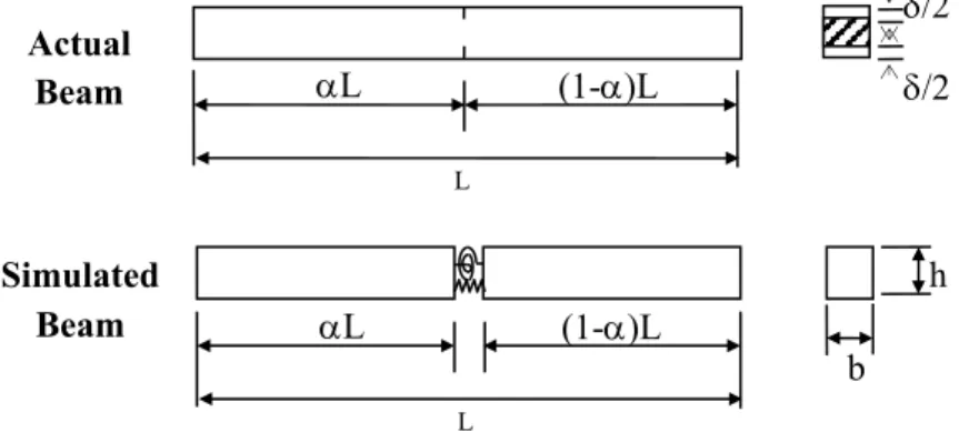
Understanding the behavior of beams and bars can pave the way towards understating more complex structures and yet simple to study. Cracks can be simulated using open cracks models which are simple and can effectively simulate reality, particularly in low frequency range (Friswell and Penny, 2002). One widely used open crack model, is to divide the beam into two segments con-nected by springs (Fernandez-Saez et al. 1999; Bamnios et al. 2002; Lin et al. 2002; Patil and Maiti, 2003; Law and Lu, 2005), as shown in Figure 1. It is proven that cracks decrease the natural fre-quencies (Shahdin et al. 2009; Curyet al. 2011).
Fernandez-Saez et al. (1999) developed an approximate method to calculate the fundamental frequency of a cracked simply supported Euler-Bernoulli beam. Yang et al. (2008) investigated ana-lytically the response of a cracked Euler-Bernoulli beam made of Functionally Graded Material (FGM) under axial compressive load and transverse moving load, for single and multiple cracks. Sinha et al. (2002) proposed a simplified analysis to detect open crack properties based on updating a finite element model using measured natural frequencies. While Kamali Yazdi et al. (2015) devel-oped a new cracked 2D finite element to simulate embedded and surface cracks.
Figure 1: Cracked 1-D Structure.
Xu et al. (2007) proposed an iterative approach based on perturbation theory to detect damage using the changes in the first few natural frequencies. Kisa and Gurel (2006) studied the change in the first three natural frequencies and mode shapes for a cracked beam with circular cross-section.
Not only Euler-Bernoulli beams received researchers' attention, but also Timoshenko beams (Kim and Kim, 2003; Chang and Chen, 2004; Masoud et al. 2006; Masoud and Al-Said, 2009; Kar-garnovin et al. 2012) and Frames (Rezaiee-Pajand et al. 2014) were in the focus.
Crack detection in bars, rods and shafts is particularly important as they are used in all rotating machines and gearboxes, and may lead to tragic accidents (Samuel and Pines 2005). Ruotolo and Surace (2004) derived expressions for the natural frequencies of bars with multiple cracks. Chon-dros et al. (1997, 1998) derived the governing differential equation of a cracked bar. Dilena and Morassi (2009) developed a numerical model to detect damage in rods using natural and anti-resonant frequencies.
L (1-)L
L
/2 /2
Actual Beam
L (1-)L
L
h
b
In the present study, the inverse problem, of cracked Euler-Bernoulli beams, will be addressed. The change in natural frequencies will be utilized to check the existence of a crack and quantify it. As crack quantification requires evaluating its location and depth, at least two measurements are needed i.e. two or more natural frequencies. If a crack is located near a nodal point, the natural frequency will not exhibit any change regardless of the crack severity. Accordingly, more modes are needed to avoid this drawback.
Available studies in the literature analyze beam and bar problems separately while the differ-ence between a bar and a beam is the loading direction. However, axial and bending modes will continue to be structural properties regardless of the loading condition. In this analysis, unlike other approaches that uses more than one natural frequency from the same direction either axial or end-ing, a mixture of axial and bending natural frequencies will be used here to quantify the crack. The two measurements needed to quantify a single crack will be the first axial and bending natural fre-quencies measured for the possibly cracked beam. This model is simple, yet efficient. Another major advantage of the present approach is that it requires neither prior knowledge of the natural fre-quencies of the intact beam nor any historical measurements.
This study consists of five sections including this introduction. In Section 2, the mathematical model will be presented. The proposed solution will be described in section 3, and case studies are presented in section 4. Testing the ability to deal with multiple cracks are also included in section 4. Concluding remarks are comprised in section 5.
2 MATHEMATICAL MODEL
2.1 Model Assumptions
The cracked beam of concern, as shown in Figure 1 has the following properties:
- Beam is made of an isotropic, homogeneous, linearly, elastic material. Uncertainties of material properties are not considered.
- The beam is a uniform, slender, Euler-Bernoulli beam, which implies shear deformation is ne-glected.
- The beam contains a single double-edge open crack with depth δ that is located along the beam at L.
- The crack will be represented by massless axial and rotational springs to introduce displace-ment discontinuity in the axial direction and slope discontinuity in the transverse direction re-spectively.
- The change in beam mass due to the crack is negligible.
2.2 Bar Problem
The bar is divided into two segments at the crack location, and connected by a linear spring. The spatial distribution of the displacement field of each segment is given by (Dilena and Morassi, 2009):
x
C
1cos
x
C
2sin
x
,
i
1
,
2
u
i i
j i
j (1)Where ui is the axial displacement and i denotes the left and right segments of the bar. The
wave number j is related to the cracked bar natural frequency by (Dilena and Morassi, 2009):
E
j a j
, (2)Where a,j is the j-th axial natural frequency of the bar, E and are the modulus of elasticity
and mass density as defined in the previous section. The constants
C
ki can be evaluated by apply-ing the boundary and compatibility conditions.From the axial motion perspective of a beam, the boundary conditions for Fixed-Free are the same for Fixed-Roller, and Hinged-Roller conditions. They are given by:
0
0
11,
2
0
1
C
u
L
u
(3)At the crack location, the displacement is discontinuous while its derivative is continuous. The discontinuity of the displacement is related to the elongation in the linear spring. These conditions are given by:
L
u
L
u
1
2
,
u
L
u
L
EA
K
L
u
a
1 2
1
(4)
Where Ka is the axial spring stiffness representing the crack. This stiffness is a function of both the material properties and crack depth ratio, and will be discussed in a later section.
Applying the boundary conditions and compatibility conditions given by Eq. (3) and (4) and solving for Ka, we get:
L
L
L
EA
K
j j
j j
a
cos
2
tan
tan
(5)
The expression given by Eq. (5) relates the natural frequency of the cracked bar to the crack properties, in terms of location and depth. As indicated earlier, this expression is valid for beams with Fixed-Free, Fixed-Roller and Hinged-Roller boundary conditions.
Similarly, for Fixed-Hinged and Hinged-Hinged beams, the compatibility conditions will hold while the boundary conditions are given by:
11 1
0
0
C
Applying the boundary conditions and compatibility conditions given by Eq. (6) and (4) respec-tively, and solving the resulting equations for the spring stiffness gives:
2
1
cos
cos
sin
2
L
L
L
EA
K
j j
j j a
(7)
2.3 Beam Problem
For beam problem we follow the same procedure described in section 2.2 to derive relations similar to (5) and (7). For the beam problem, the crack is represented by a rotational spring.
The spatial distribution of the bending displacement of the beam segments to the left and right of the crack are given by:
x
D
1cos
x
D
2sin
x
D
3cosh
x
D
4sinh
x
,
i
1
,
2
w
ji j i
j i j i
i
(8)Where i denotes the left and right segments and j is given by (Patil and Maiti, 2003):
EI
A
j r j
2, 4
(9)
Where r,j is the j-th bending natural frequency. As known, the boundary conditions for the
above mentioned cases as follows: Fixed end:
0
1 1
w
w
(10)Hinged and Roller end:
0
1 1
w
w
(11)Free end:
0
1 1
w
w
(12)Where i denotes either left or right ends.
For compatibility at the crack location, the continuity is maintained for the displacement, the shear force and bending moment, while the slope is not regardless of the beam boundary conditions. They are given by (Patil and Maiti, 2003):
2
,
1
2
,
1
3
,
1
L
w
L
w
L
w
L
w
L
w
L
w
w
L
w
L
EI
K
L
w
r
1 2
1
(13)
Where Kr is the rotational spring stiffness equivalent to the crack.
wave number j appears as a common factor with powers corresponding to the degree of
differentia-tion. Since it has a positive non-zero value, it will be crossed out from these equations.
For Fixed-Free beam, to get a nonzero solution of Eq. (23) in the appendix, the determinant of the coefficient matrix must vanish, which leads to the following solution for Kr:
1
,
4
1
L
Ch
L
C
EI
K
r
2
1
2
2
1
1
2
1
1
1
2
2
2
1
L
S
L
Sh
L
Sh
L
C
L
C
L
Sh
L
Ch
L
S
L
S
L
Ch
L
Sh
L
C
S
Ch
Sh
C
(14)Where C, S, Ch and Sh in equations (14) stand for cosine, sine, hyperbolic cosine and hyperbol-ic sine functions respectively. This notation will be used throughout this research. is given by:
L
(15)The expression above matches the one derived by Patil and Maiti (2003):
Similarly, for the rest of the boundary conditions the same procedure is utilized. The nonzero solution of Eq. (24), for Hinged-Hinged or Hinged-Roller is obtained when the determinant of the coefficient matrix vanishes, which leads to the following solution for Kr:
L
Sh
L
Ch
L
Ch
L
S
L
C
L
C
EI
K
r
1
2
1
2
4
(16)Again, the expression above matches the one derived by Patil and Maiti (2003). For Fixed-Roller and Fixed-Hinged beams, solving Eq. (25), for Kr gives:
,
4
2
L
S
L
h
C
L
Sh
L
C
EI
K
r
1
1
4
2
1
2
1
2
1
2
2
1
2
1
2L
Sh
L
S
L
Sh
L
S
L
Sh
L
S
L
Sh
L
S
L
Sh
L
S
L
Ch
L
C
L
Ch
L
C
(17)2.4 Spring Stiffness-Crack Relation
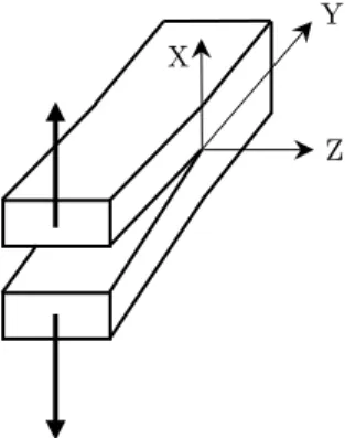
Several expressions relate the spring stiffness to crack depth can be found in the literature (e.g. Haisty and Springer 1988; Ostachowicz and Krawczuk 1991; Patil and Maiti 2003; Ruotolo, and Surace 2004). These relations are based on fracture mechanics. The expressions, utilized here, have one thing in common; they all assume Mode I stress field where the surfaces of the crack moves in opposite directions as shown in Figure 2. This stress intensity factor is given by (Ostachowicz and Krawczuk 1991):
h
f
Where is the plane stress and f(δ) is a function depends on the loading condition and crack type in case of bending, whether it is single side or double edge. Interested readers can follow the formulation of these expressions in the indicated references.
For open crack with total depth δ under axial loading, the axial spring stiffness expression is given by Ruotolo and Surace (2004):
S
EA
h
K
a2 1
2
1
(19)
Where:
0.713
81.0368
7 0.5803
61.2055
51.0368
40.2381
30.9852
2 SThe axial spring stiffness for bars does not change if the crack is single sided or double-edge. For the rotational spring stiffness, several expressions are presented in literature that simulate an open crack in bending motion. The spring expression in case of double edge crack and single side cracks are as follows:
For double-edge crack (Haisty and Springer 1988):
2 3 4
2 2
1
36
0
.
5033
0
.
9022
3
.
412
3
.
181
5
.
793
E
bh
K
r (20a)For single side crack (Ostachowicz and Krawczuk, 1991):
2 3 4 5 6
2 2
1
72
0
.
6384
1
.
035
3
.
7201
5
.
1773
7
.
53
7
.
332
2
.
4909
E
bh
K
r (20b)With the appropriate spring expression, depending on crack type and direction of loading , the present model holds to be true to simulate both single side crack, occurring due to fluctuating load-ing, and double sided crack, occurring due to cyclic loading (Ostachowicz and Krawczuk, 1991). It should be noted that for single side crack, the expression given by (20b) does not change regardless of the crack being on the top side or the bottom side of the beam. Hence, this model cannot distin-guish if the crack on the top or the bottom side of the beam.
Figure 2: Mode I stress field. X
Y
3 INVERSE PROBLEM
For a given crack located at distance L, measured from the left end, and total depth ratio , the solution procedure will be briefly described. To detect the crack location and depth using measure-ment of the longitudinal and bending natural frequencies, one can follow the procedure summarized as follows:
1.Measure the first axial and bending natural frequencies. In absence of the measurements, pro-cedure can be tested using numerically calculated natural frequencies. The measurement techniques of the natural frequencies are beyond the scope of this research.
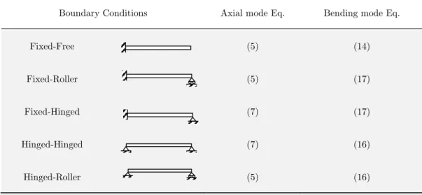
2.According to the beam boundary conditions, select the two appropriate equations derived for both axial and bending modes as per Table 1 below.
3.Substitute the natural frequencies, from step (1), in the right hand sides of the corresponding equations.
4.With unknown, use expressions given by Eq. (18) and (19) to evaluate the left hand side of equations selected in step (2).
5.Solve the resulting coupled system of equations for the crack depth and location .
The above procedure can be applied not only to the first natural frequencies but also to higher frequencies that can be used to confirm the accuracy of the crack quantification.
It worth noting that the above procedure can be applied using any combination of axial and bending natural frequencies, not necessarily to be first natural frequency in each direction. This allows using higher natural frequencies to confirm the accuracy of the predicted crack quantification as discussed below. Moreover, this procedure can be applied to quantify more than one crack. If the number of cracks is already estimated, using enough number of natural frequencies in each direc-tion, and applying the compatibility conditions at each crack will lead to set of equations with crack locations and depths are unknown. Solving these equations leads to estimate the location and depth of each crack.
Boundary Conditions Axial mode Eq. Bending mode Eq.
Fixed-Free (5) (14)
Fixed-Roller (5) (17)
Fixed-Hinged (7) (17)
Hinged-Hinged (7) (16)
Hinged-Roller (5) (16)
4 NUMERICAL VALIDATION
4.1 Natural Frequencies Evaluation Using Finite Element Method
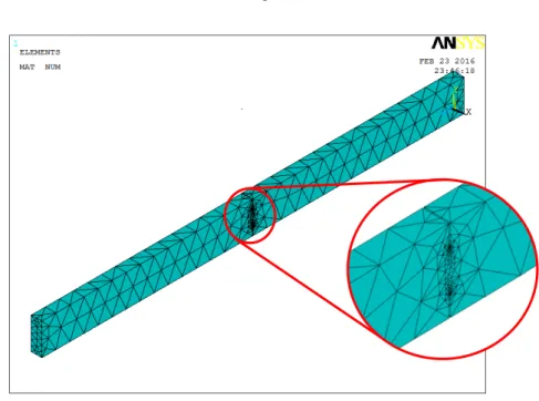
To the best of authors’ knowledge, there is no published measurements for the natural frequencies of a cracked beam in axial and bending directions. Therefore to test the proposed procedure, and due to lack of measurements, finite element method (FEM) is utilized to calculate the natural fre-quencies of cracked cantilever beam described in Table 2. The FEM is constructed in the commer-cial package, ANSYS®, as shown in Figure 3. Utilizing the FEM allows to provide an independent platform for evaluating the natural frequencies necessary for the proposed procedure. The beam is meshed using ANSYS built-in tetrahedral elements SOLID187. The SOLID187 is a 10-node element that is used in analysis of 3-D models. Figure 4 shows a schematic sketch showing the 10 nodes of this element. The Mesh density is increased near the crack tip. The beam is cracked with double-edge open crack simulated by two sharp wdouble-edges removed away from the beam. The crack is as-sumed to vary in location and depth. The location of the crack starts from 100 mm to 700 mm from the fixed end with step of 100 mm. while the crack depth ranges from 10% to 90% of the section depth for these locations.
Beam Dimensions Material Properties
L b h E
800mm 20mm 60mm 210 GPa 7800 kg/m3 0.3
Table 2: Beam Specifications.
Figure 4: Schematic sketch of tetrahedral SOLID187 element
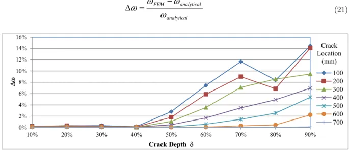
To evaluate the accuracy of the natural frequencies obtained using ANSYS, the natural fre-quencies have been calculated analytically by solving the relations derived in section 2 for the wave numbers and for the axial and bending modes respectively for each crack location L and depth . The relative difference in estimating the natural frequency by both FE and analytical models is defined by the following relation for both axial and bending frequencies:
analytical analytical FEM
(21)0% 2% 4% 6% 8% 10% 12% 14% 16%
10% 20% 30% 40% 50% 60% 70% 80% 90%
Crack Depth
100 200 300 400 500 600 700 Crack Location
(mm)
Figure 5: Relative difference in estimating first bending natural frequency of cantilever beam.
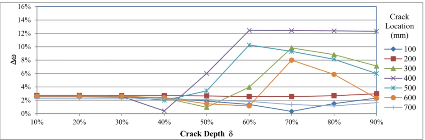
Figure 5 and Figure 6 show the relative difference in estimating the first two natural frequencies in bending directions as per equation (21). The relative difference in the axial direction is found to be less than 1%. It can be seen that the error is acceptable in the entire range except when the crack depth exceeds 60% of the depth.
1
2
3
4
5 6
7 9
0% 2% 4% 6% 8% 10% 12% 14% 16%
10% 20% 30% 40% 50% 60% 70% 80% 90%
Crack Depth
100 200 300 400 500 600 700 Crack Location
(mm)
Figure 6: Relative difference in estimating second bending natural frequency of cantilever beam.
One final remark has to be indicated here, to help interpreting results shown in the coming sec-tion, is that ANSYS FE model has overestimated the axial natural frequency. This caused the axial natural frequency for a small crack to be slightly greater than the axial natural frequency for intact beam. Hence, the method in hand fails to predict these cracks. However, this can be detected in early beginning by comparing the natural frequencies of intact beam with the estimated naturals frequencies obtained by numerical simulation, or measurements obtained in lab or real life testing.
4.2 Higher Order Modes
During preliminary numerical studies, it was noticed that the method is not able to detect some crack with a reasonable accuracy using the first axial and bending modes. This is attributed to ac-curacy of the natural frequencies estimation using ANSYS. To improve the results, the second axial and second bending natural frequencies were also used along with the first ones. This gives four different combinations of the axial and bending natural frequencies. This allows confirming the cor-rectness of the detection of other combinations, or providing a different solution when it cannot be obtained using other combination(s). Additional combinations can be used if higher modes where made available.
4.3 Case Studies
For the cantilever beams with dimensions and cracks described earlier, and with the natural fre-quencies, estimated using ANSYS FEM, four combinations of the natural frequencies have been used; these combinations are as follows:
-Combination I: 1st axial mode with the 1st Bending mode,
-Combination II: 1st axial mode with the 2nd Bending mode,
-Combination III: 2nd axial mode with the 1st Bending mode,
-Combination IV: 2nd axial mode with the 2nd Bending mode.
1
100
%
%
100
1
Pr Pr
edict Actual
edict Actual
SR
SR
(22)
Where the subscripts Actual and Predict are the actual and predicted crack property respective-ly. Points with ratio of 0% are the points where crack detection has failed, while approaching 100% indicates accurate crack location detection.
Here, the accuracy of crack detection is related to the total length of the beam rather than to the correct location of the crack. This is more realistic, since, in practical aerospace and wind ener-gy applications, the beam-like components searched for cracks, such as aircraft wings and wind turbine blades, are usually large. Accordingly, it indicates the actual search area for the crack out of the total beam length. In other words, it shows the saved effort in searching the entire beam. For example, if the error in crack location is 10% of beam length, in a 60m wind turbine blade or civil aircraft wing, the total search area will be 6 meters instead of searching the whole 60 meters. This enormously reduces the effort, down time, and hence inspection cost. Figures from Figure 7 through Figure 13 show SRj for various crack location and depths. In each figure, all crack depths are
exam-ined for the same crack location. At each point, SRj of the detection of crack location and depth is
calculated using equation (22) for all combinations.
It can be noticed that at least one combination achieves reasonably high success ratio indicating reasonably accurate prediction. However, as indicated earlier, some cracks have not been detected with certain combinations. This is attributed to the estimation accuracy of the natural frequencies in FEM. Hence, more accurate estimation of the natural frequencies will lead to more accurate crack detection. For crack with depth 10%, the FEM overestimated the axial natural frequencies so that their values are greater than of the natural frequencies of the intact beam. This causes the proposed method to fail in the prediction of the crack.
0% 20% 40% 60% 80% 100%
SR
Combination ICrack Properties Sucess Ratio (Combination II Combination III Combination IV
Actual=12.5%)0% 20% 40% 60% 80% 100%
10% 20% 30% 40% 50% 60% 70% 80% 90%
SR
δ
Crack Depth
0% 20% 40% 60% 80% 100%
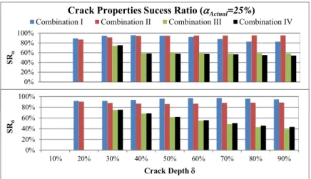
SR
Combination ICrack Properties Sucess Ratio (Combination II Combination III Combination IV Actual=25%)
0% 20% 40% 60% 80% 100%
10% 20% 30% 40% 50% 60% 70% 80% 90%
SRδ
Crack Depth
Figure 8: Crack Properties Estimation Success Ratio (for crack located at 200mm).
0% 20% 40% 60% 80% 100%
SR
Combination ICrack Properties Sucess Ratio (Combination II Combination IIIActual Combination IV =37.5%)
0% 20% 40% 60% 80% 100%
10% 20% 30% 40% 50% 60% 70% 80% 90%
SRδ
Crack Depth
Figure 9: Crack Properties Estimation Success Ratio (for crack located at 300mm).
0% 20% 40% 60% 80% 100%
SR
Combination ICrack Properties Sucess Ratio (Combination II Combination IIIActual Combination IV =50%)
0% 20% 40% 60% 80% 100%
10% 20% 30% 40% 50% 60% 70% 80% 90%
SRδ
Crack Depth
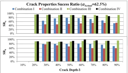
0% 20% 40% 60% 80% 100%
SR
Combination ICrack Properties Sucess Ratio (Combination II Combination III Combination IV Actual=62.5%)
0% 20% 40% 60% 80% 100%
10% 20% 30% 40% 50% 60% 70% 80% 90%
SRδ
Crack Depth
Figure 11: Crack Properties Estimation Success Ratio (for crack located at 500mm).
0% 20% 40% 60% 80% 100%
SR
Combination ICrack Properties Sucess Ratio (Combination II Combination IIIActual Combination IV =75%)
0% 20% 40% 60% 80% 100%
10% 20% 30% 40% 50% 60% 70% 80% 90%
SRδ
Crack Depth
Figure 12: Crack Properties Estimation Success Ratio (for crack located at 600mm).
0% 20% 40% 60% 80% 100%
SR
Combination ICrack Properties Sucess Ratio (Combination II Combination IIIActual Combination IV =87.5%)
0% 20% 40% 60% 80% 100%
10% 20% 30% 40% 50% 60% 70% 80% 90%
SRδ
Crack Depth
5 DISCUSSION AND CONCLUSIONS
The proposed approach is a simple straight forward procedure to solve the inverse problem of crack detection in Euler-Bernoulli beams. The approach can be applied to any set of boundary conditions. In general, utilizing this approach gives accurate results in estimating the crack properties in terms of crack location and depth. However, the error in estimating the crack properties is affected by accuracy of the natural frequency measurements or estimation. Using different combinations of axial and bending natural frequencies give a set of crack properties estimations. These estimations help increasing the accuracy of the crack prediction and highly reducing the total search area for cracks within the structure, leading to enormous saving in effort, downtime and cost.
References
Adewuyi, A. P., Wu Z., Serker N. H. M. (2009). Assessment of vibration-based damage identification methods using displacement and distributed strain measurements, Structure Health Monitoring 8:443-461, 2009.
Bamnios, Y., Douka, E., Trochidis, A. (2002). Crack identification in beam structures using mechanical impedance, Journal of Sound and Vibrations 256:287-297.
Bouboulas, A. S., Anifantis, N. K. (2001). Finite element modeling of vibrating beam with a breathing crack: obser-vations on crack detection, Structure Health Monitoring 10:131-145.
Chang, C. C., Chen, L. W. (2004) Damage detection of cracked thick rotating blades by a spatial wavelet based approach, Applied Acoustics 65:1095-1111.
Chen, X. F., Zi, Y. Y., He, Z. J. (2006). Identification of multiple cracks using a dynamic mesh-refinement method, The Journal of Strain Analysis for Engineering Design 41:31-41.
Chondros, T. G., Dimarogonas, A. D., Yao, J. (1997). A consistent cracked bar vibration theory, Journal of Sound and Vibrations 200:303-313.
Chondros, T. G., Dimarogonas, A. D., Yao, J. (1998). Longitudinal vibration of a continuous cracked bar, Engineer-ing Fracture Mechanics 61:593-606.
Cury, A., Borges, C., Barbosa, F. (2011). A two-step technique for damage assessment using numerical and experi-mental vibration data, Structure Health Monitoring 10:417-428.
Dilena, M., Morassi, A. (2009). Structural health monitoring of rods based on natural frequency and antiresonant frequency measurements, Structure Health Monitoring 8:149-173.
Fan W., and P. Qiao (2001). Vibration-based damage identification methods: a review and comparative study, Structure Health Monitoring 10:83-111.
Fernandez-Saez, J., Rubio, L., Navarro, C. (1999). Approximate calculations of the fundamental frequency for bend-ing vibration of cracked beams, Journal of Sound and Vibrations 225:345-352.
Friswell, M. I., Penny, J. (2002). Crack modeling for structural health monitoring, Structure Health Monitoring 1:139-148.
Haisty, B. S., Springer, W. T. (1988). A general beam element for use in damage assessment of complex structures, Journal of Vibration, Acoustics, Stress, and Reliability in Design 110:389-394.
Kamali Yazdi, A., Shooshtari, A., Fazelipour, M. (2015). Introducing new cracked finite elements and a method for SIF calculation of cracks, Mechanics Based Design of Structures and Machines: An International Journal, DOI: 10.1080/15397734.2015.1045071.
Kim, S. S., Kim, J. H. (2003). Rotating composite beam with a breathing crack, Composite Structures 60:83-90. Kisa, M., Gurel, M. A. (2006). Modal analysis of multi-cracked beams with circular cross-section, Engineering Frac-ture Mechanics 73:963-977.
Law, S. S., Lu, Z. R. (2005). Crack identification in beam from dynamic responses, Journal of Sound and Vibrations 285:967-987.
Liang, R. Y., Hu, J., Choy, F. (1992). Quantitative NDE technique for assessing damages in beam structures, Jour-nals of Engineering Mechanics 118:1468-1487.
Lin, H. P., Chang, S. C., Wu, J. D. (2002). Beam vibrations with an arbitrary number of cracks, Journal of Sound and Vibrations 258:987-999.
Loya, J. A., Rubio, L., Fernandez-Saez, J. (2006). Natural frequencies for bending vibrations of Timoshenko cracked beams, Journal of Sound and Vibrations, 290:640-653.
Masoud, A. A., Al-Said, S. A. (2009). New algorithm for crack localization in a rotating Timoshenko beam, Journal of Vibration and Control 15:1541-1561.
Masoud, S., Naji, M., Al-Shukry, A. A. (2006). Flexural vibration of rotating cracked Timoshenko beam, Journal of Vibration and Control 12:1271-1287.
Montalvao, D., Maia, M. M., Ribeiro, M. R. (2006). A review of vibration-based structural health monitoring with special emphasis on composite materials, Shock Vibration Digest 38:295-324.
Ostachowicz, W. M., Krawczuk, M. (1991). Analysis of the effect of cracks on the natural frequencies of a cantilever beam, Journal of Sound and Vibrations 150:191-201.
Patil, D. P., Maiti, S. K. (2003). Detection of multiple cracks using frequency measurements, Engineering Fracture Mechanics 70:1553-1572.
Rezaiee-Pajand, M., Kazemiyan, M. S., Aftabi. S. A. (2014). Static damage identification of 3D and 2D frames, Mechanics Based Design of Structures and Machines: An International Journal 42:70-96.
Ruotolo, R., Surace, C. (2004). Natural frequency of a bar with multiple cracks, Journal of Sound and Vibrations 272:301-316.
Samuel, P. D., Pines, D. J. (2005). A review of vibration-based techniques for helicopter transmission diagnostics, Journal of Sound and Vibrations 282:475-508.
Sekhar, A. S. (2008). Multiple cracks effects and identification, Mechanical Systems and Signal Processing 22:845-878.
Shahdin, A., Morlier, J., Gourinat, Y. (2009). Correlating low-energy impact damage with changes in modal parame-ters: a preliminary study on composite beams, Structure Health Monitoring 8:523-536.
Sinha, J. K., Friswell, M. I., Edwards, S. (2002). Simplified models for the location of cracks in beam structures using measured vibration data, Journal of Sound and Vibrations 251:13-38.
Xu, G. Y., Zhu, W. D., Emory, B. H. (2007). Experimental and numerical investigation of structural damage detec-tion using changes in natural frequencies, Journal of Vibradetec-tions and Acoustics 129:686-700.
Yang, J., Chen, Y., Xiang, Y., Jia, X. L. (2008). Free and forced vibration of cracked inhomogeneous beams under an axial force and a moving load, Journal of Sound and Vibrations 312:166-181.
Appendix
The boundary and compatibility conditions cast in matrix form for:
L Ch L Sh L C L S L Sh L Ch L S L C Ch EI K Sh EI K C EI K S EI K Ch EI K Sh Sh EI K Ch C EI K S S EI K C Ch Sh C S Ch Sh C S Sh Ch S C Sh Ch S C Sh Ch S C Sh Ch S C r r r r r r r r 0 0 0 0 0 0 0 0 0 0 0 0 1 0 1 0 0 0 0 0 0 1 0 1 (23)
- Cracked simply supported (either Hinged-Hinged or Hinged-Roller) beams:
L Sh L Ch L S L C L Sh L Ch L S L C Ch EI K Sh EI K C EI K S EI K Ch EI K Sh Sh EI K Ch C EI K S S EI K C Ch Sh C S Ch Sh C S Sh Ch S C Sh Ch S C Sh Ch S C Sh Ch S C r r r r r r r r 0 0 0 0 0 0 0 0 0 0 0 0 0 1 0 1 0 0 0 0 0 1 0 1 (24)
- Cracked Fixed-Hinged and Fixed-Roller beams: