Lat. Am. j. solids struct. vol.11 número9
Texto
Imagem


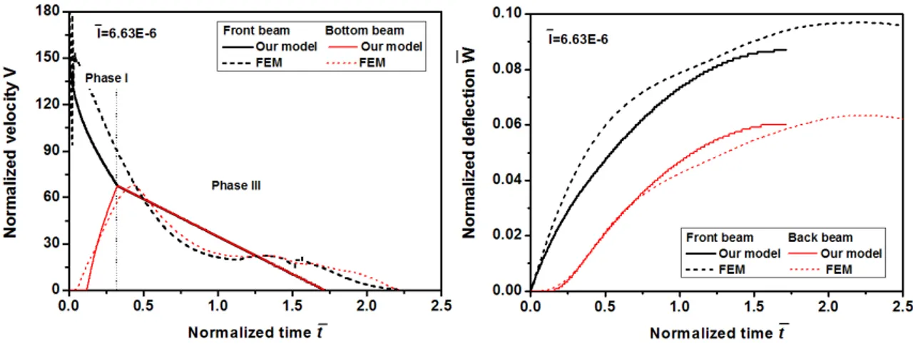
![Figure 7 Velocity versus time histories of the mid-span of the front and back faces in three regimes: regime A- strong core; regime B- densification reaches before the velocities equalization; regime C- soft core [4]](https://thumb-eu.123doks.com/thumbv2/123dok_br/18885207.423664/16.892.147.797.770.949/figure-velocity-histories-regimes-densification-reaches-velocities-equalization.webp)


Documentos relacionados
Modified generalized pushover procedure, modal pushover analysis and incremental dynamic analysis of a bridge with elevated pile foun- dation systems are conducted.. The results
In a previous study, Zhang and Yu (2012) employed ping-pong balls to study the dynamic buck- ling behaviors of spherical shells impinged onto a rigid plate by means of air-gun
Analytical solutions for the buckling configurations of beams and the natural frequencies of vibration around the buckled beam are obtained for a variety of non-classical
Simulation of irregular waves over submerged obstacle on a NURBS potential numerical wave tank..
It will be evaluated the deceleration of the model and the Von Mises stress level in the elements that make up the screws that hold the seat structure in side
Bearing in mind the most important mission of proposed controller to achieve most appropriate vibration and noise reduction of wiper blade in frequency domain
Latin American Journal of Solids and Structures 11 (2014) 1515-1540 Finally, for the elastically supported rectangular plate resting on Winkler elastic foundation
Small scale effect on the buckling analysis of single-layered graphene sheet embedded in an elastic medium based on nonlocal plate theory, Physica E 42:
