Abstract
The paper presents experiments involving punching of RC slabs strengthened using externally bonded carbon fiber reinforced po-lymer (CFRP) sheet and textile reinforced mortar (TRM). Twelve RC slab specimens of two concrete grades (39.9 and 63.2 MPa) and employing two strengthening schemes (CFRP and TRM) were tested. Specimens were supported on two opposite edges. Experi-mental load-displacement variations show two peak loads in strengthened slabs and one peak followed by a plateau in control. Second peak or the plateau corresponds to the combined action of aggregate interlock and the dowel action of back face rebars and strengthening layers. The dowel action of back face rebars and strengthening layers had no role in ultimate punching load (i.e. first peak). Strengthened slabs showed 9-18% increase in ultimate punching load (i.e. first peak) whereas there was significant in-crease in the second peak load (190-276% for CFRP; 55-136% for TRM) and energy absorption (~66% for CFRP and 22-56% for TRM). An analytical model was also developed for predicting the punching shear strength (first and second peaks) of strengthened slabs showing good comparison with experiments.
Keywords
Punching; Slab; Concrete; Strengthened; CFRP; TRM; Dowel action.
Effect of CFRP and TRM Strengthening of RC Slabs
on Punching Shear Strength
1 INTRODUCTION
Punching shear failure of reinforced concrete (RC) slabs is a major concern for the structural de-signers of buildings and bridges. This type of failure is more common in bridge decks supported by girders under the action of repeated wheel loads (Meier, 1992; Hassanzadeh and Sundqvist, 1998; Malvar et al., 2000; Oh and Sim, 2004). The bridge decks are often strengthened for flexure by ex-ternal bonding of Fiber Reinforced Polymer (FRP) sheets but the consequent enhancement in shear strength is generally low and not well known. Many previous studies have examined the punching
Husain Abbas* a Aref A. Abadel a Tarek Almusallam a Yousef Al-Salloum a
aDept. of Civil Engineering, King Saud
Univ., Riyadh 11421, Saudi Arabia.
*Author email:
http://dx.doi.org/10.1590/1679-78251277
Latin A m erican Journal of Solids and Structures 12 (2015) 1616-1640
that CFRP strengthening leads to significant improvements in the structural behaviour of slab-column connections. The increase in punching capacity of strengthened slabs was up to 29%, while the increase in stiffness was up to 80%. Abbas et al., (2004) studied the behavior of circular con-crete plates strengthened with steel skin under drop hammer loading. Cantwell and Smith (1999) showed that the quasi-static and dynamic flexural strength of concrete can be greatly enhanced by bonding a relatively thin CFRP skin to the lower surface of beams.
Chen and Li (2005) used Glass Fiber Reinforced Polymer (GFRP) laminates for the shear strengthening of slabs. They showed that the flexural strengthening of slabs by external bonding of GFRP laminates can increase the punching strength, significantly. However, GFRP laminates were more effective for the slabs with low steel reinforcement ratios. They proposed analytical equations to calculate the punching strength of strengthened slabs. Abdullah et al., (2013) investigated the effectiveness of bonding non-prestressed and prestressed CFRP plates to the tension surface of RC column-slab connections in the strengthening of slabs. They found that the use of prestressed CFRP plates improved the serviceability but did not enhance the ultimate behavior as much as the non-prestressed CFRP plates. The development of the critical diagonal crack was the main reason for the reduction in the ultimate capacity of the strengthened slabs. Textile reinforced mortar (TRM) is emerging as a promising alternative to FRP for concrete applications due to the elimination of or-ganic binders of FRP composites with inoror-ganic ones i.e. cement-based mortar (RILIM TC 201TRC, 2006; Triantafillou, 2006; Triantafillou and Papanicolaou, 2006; Pled and Mobasher, 2007; Papanicolaou et al., 2009; Al-Salloum et al., 2011; Alhaddad et al., 2012; Arboleda et al., 2012). Textiles comprise fabric meshes made of long woven, knitted, or even unwoven fiber roving in at least two (typically orthogonal) directions. TRM was investigated in this study as a new method for the strengthening of concrete slabs. TRM used in this study consist of textile meshes made of car-bon fibers roved in two directions and cement mortar serving as binder, containing polymeric addi-tives.
Oh and Sim (2004) proposed an analytical model for predicting the punching shear strength of bridge decks strengthened using external strengthening techniques. The proposed punching shear model was used for predicting the ultimate shear strength of slabs strengthened using different ma-terials. Sharaf et al., (2006) studied the effect of retrofitting interior slab–column connections against punching shear failure with externally bonded CFRP strips. The results show 29% to 60% increase in stiffness and 6% to 16% increase in punching capacity. An analytical model was refined to predict the punching shear capacity of the specimens strengthened with CFRP strips. Rochdi et al., (2006) developed an analytical model to predict the punching failure load of RC slabs with ex-ternally bonded FRP sheets based on the integration of the tensile stresses around the punching crack and the dowel effect of reinforcing bars and FRP sheet. Farghaly and Ueda (2011) investigat-ed experimentally and analytically the punching shear capacity of CFRP strengtheninvestigat-ed two way slabs. The results showed up to 40% increase in the punching capacity of slabs. An analytical model was also developed for predicting the punching shear strength of strengthened RC slabs.
Latin A m erican Journal of Solids and Structures 12 (2015) 1616-1640 that is suited for adoption in practice with confidence. The paper studies the effect of CFRP and TRM strengtheneing of RC slabs, commonly adopted for their flexural strengthening, on the punch-ing shear resistance of slabs and provides an analytical method for its prediction.
2 EXPERIMENTAL PROGRAM
The RC slabs of 600 × 600 × 90 mm size and reinforced with
8@100 mm c/c bars (0.71% steel) were used in this study. The slabs were singly reinforced with rebars provided on the rear face of the slab. The reinforcement details of slabs are shown in Figure 1. Six slabs each were casted in two concrete grades thus making a total of twelve slab specimens. Two RC slabs of each group were taken as control whereas the remaining four slabs were strengthened using two different schemes of external strengthening. The materials used for strengthening were CFRP and TRM. The CFRP and TRM were applied on the rear face of slabs (Figure 1). The details of experimental program are given in Table 1.Slab specimens of the two concrete grades A and B were cast in two separate batches. The spec-imens were cast in wooden moulds. The fabricated steel cages with cover blocks were placed in the mould. Concrete with 10 mm maximum size of aggregate and a slump of 18 mm was used for the casting of slabs. The casting was done in a single layer and compacted by a pin vibrator. Immedi-ately after casting, screeding of top surface of the slab was done and then the slab specimens were covered with moist burlap and polythene sheets. Subsequently, the specimens were subjected to intermittent spraying of water every day for two weeks and then the form was removed and speci-mens were left to dry for the next two weeks. Three companion standard concrete cylinders (150 × 300 mm) were cast for each grade of concrete. The cylinders were cured in the water tanks for 28 days and tested in accordance with ASTM C39 (2012). The average compressive strength of con-crete for the two grades was 39.9 and 63.2 MPa respectively. The rebars of 8 mm diameter were tested in accordance with ASTM A370 (2012) and the average yield strength was 510 MPa.
Latin A m erican Journal of Solids and Structures 12 (2015) 1616-1640 Slab specimen ID Concrete grade Strengthening scheme
SA-1,2 A None
SA-C1,2 A Single sheet of unidirectional CFRP with
fibers along span direction
SA-T1,2 A Two layers of bidirectional TRM
SB-1,2 B None
SB-C1,2 B Single sheet of unidirectional CFRP with
fibers along span direction
B Two layers of bidirectional TRM
Total number of slab specimens = 12
Table 1: Test matrix.
2.1 CFRP System and Strengthening
The properties of composite materials are dependent on the individual components properties, the manufacturing technique and the quality control of the production process. In the present study, CFRP sheets with unidirectional fibers were employed for the strengthening of RC slab specimens. Three coupon samples were cut from the sheets to determine the average mechanical properties of the sheets. Each specimen was subjected to a gradually increasing uniaxial load until failure. The average coupon test results of CFRP system are:
Elastic modulus of CFRP in primary fibers direction = 77.3 GPa Elastic modulus of CFRP 90o to primary fibers = 40.6 MPa
Fracture strain = 1.1%
Ultimate Tensile strength = 846 MPa
Latin A m erican Journal of Solids and Structures 12 (2015) 1616-1640 a) Slab surface preparation b) CFRP impregnation
c) CFRP sheet laying d) Prepared specimens
Figure 2: Strengthening of slabs with externally bonded CFRP sheet.
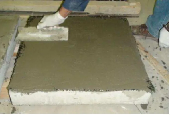
2.2 TRM Materials and Strengthening
TRM consists of two primary materials namely Textile and Mortar. Success of rehabilitation using TRM is very much dependent on the properties of these two constituents of TRM.
The textile was cut to the required length. The textile contained equal quantity of high strength carbon fiber roving in two orthogonal directions. To obtain the mechanical properties of the textile, four coupons were tested in tension and the average test results are:
Latin A m erican Journal of Solids and Structures 12 (2015) 1616-1640
In the present study, a commercial polymer modified mortar was used as mortar in TRM strengthening. To prepare the mortar for the compressive strength test, 16-18% of drinking quality water (by weight of dry powder) was put in a dry bowl; mortar was added, and then it was mixed for 3 to 5 minutes until homogeneous mixture was obtained. Molding of the specimens was then done by placing a layer of mortar about 25 mm in thickness in the cube compartments. Each layer was tamped 32 times within 10 seconds in four rounds. After tamping of the first layer in all the cube compartments, the second layer was introduced and tamped in the same manner as above. Finally, top surface of cube compartment was smoothed off with one stroke of the trowel. The spec-imens were air dried for one-day and were de-molded; the specspec-imens were then kept for water cur-ing under lab conditions for 28 days. Standard compressive strength tests were conducted as per ASTM C109 (2002) at 28 days and the average compressive strength of mortar was 33.9 MPa.
In order to determine the tensile strength of the mortar, standard Briquette specimens were pre-pared having inside faces and thickness at waistline of the briquette mold as 25 mm. Briquette spec-imens for each mortar type using same amount of water as determined for compressive strength were prepared in accordance with ASTM C190-85 (1985). A thin film of oil was coated on the inside surfaces of the Briquette molds, and were placed on base plates. The molds were filled heaping full of mortar without any compacting. The mortars were pressed in firmly with the thumbs applying a force 12 times to each Briquette. Additional mortar was added above the molds, and smoothed it off with a trowel. Oiled metal plates were placed on top of each mold; bottom and top plates were held together with the hands and turned the molds over. The process of adding and pressing addi-tional mortar above the molds, was repeated and smooth it off with a trowel. The specimens were air dried for one day. After one day of air drying, the specimens were de-molded and kept for curing under lab conditions. Before testing, each Briquette was wiped to surface-dry condition, and any loose sand grains from the surfaces were removed. Standard tensile tests were conducted at 28 days as per ASTM C190-85 (1985) and the average tensile strength of the mortar was 2.93 MPa.
Two layers of textile were used for TRM strengthening because two layers of textile were found equivalent to single layer of CFRP in an earlier study (Al-Salloum et al., 2011). The procedure adopted for affixing TRM to the slabs is shown in Figure 3.
2.3 Test Setup
Latin A m erican Journal of Solids and Structures 12 (2015) 1616-1640
3 TEST RESULTS AND DISCUSSION
3.1 Damage Pattern
The damage on the front face of the slab specimens was almost same for all specimens, as shown in Figure 5(a) for one of the slabs. The damage patterns on the rear face of control, CFRP and TRM strengthened slab specimens are shown in Figures 5(b), 6(a) and 6(b) respectively. The state of damage to concrete in the strengthened slabs was assessed by removing the layers of strengthening material as well as the loose concrete, as shown in Figure 7. The shear cone formation observed in experiments is shown in Figure 8. Examination of concrete shear cone formed in the slabs shows that the shear cone formed in CFRP and TRM strengthened slabs were almost same with the an-gles
1 and
2 varying from 60o to 65o and 15o to 20o respectively. Angle
1 being close to thevalue usually adopted by most of the codes, it is taken as 63.4o and the value of angle 2 is taken as 20.0o in punching shear calculations presented latter.
(a) Cutting of TRM fiber (b) Sika Armatec Epocem application as bonding agent
Latin A m erican Journal of Solids and Structures 12 (2015) 1616-1640
(e) Pressing on fabric for mortar penetration (f) Saturation of I layer of fabric with mortar
(g) Laying of II layer of fabric (h) Finished strengthened slab
Figure 3: Step-by-step application of TRM.
3.2 Load-Displacement Variation and Energy Absorption
Latin A m erican Journal of Solids and Structures 12 (2015) 1616-1640
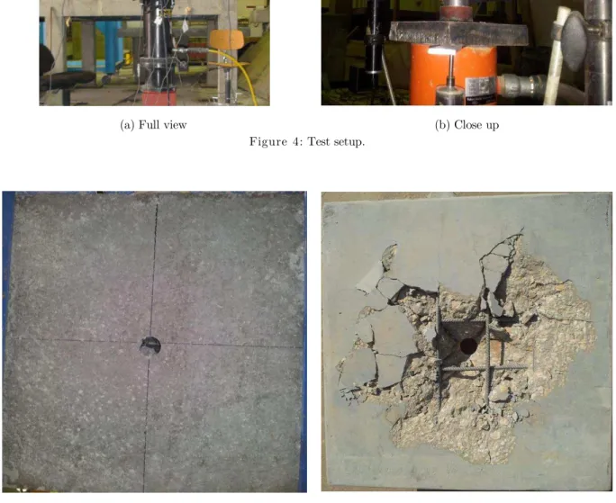
(a) Full view (b) Close up
Figure 4: Test setup.
(a) (b)
Figure 5: Punching failure of control slab of concrete grade B: (a) Front face; (b) Back face.
Latin A m erican Journal of Solids and Structures 12 (2015) 1616-1640
(a) (b)
Figure 6: Punching failure on back face of strengthened slabs of concrete grade B: (a) CFRP strengthened; (b) TRM strengthened.
(a) (b)
Figure 7: Punching failure on back face of strengthened slab of concrete grade B after removing strengthening layer: (a) CFRP strengthened; (b) TRM strengthened.
Latin A m erican Journal of Solids and Structures 12 (2015) 1616-1640 Figure 8: Punching failure model.
Latin A m erican Journal of Solids and Structures 12 (2015) 1616-1640
Figure 9: Load-displacement variation for punching of slabs for concrete grade A (SA: control slab; SA-C: CFRP strengthened slab; SA-T: TRM strengthened slab).
The first and second peak loads for different slab types are given in Table 2. The second peak load for the control slabs is taken as the load corresponding to the average plateau height.
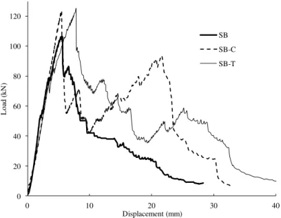
Figure 10: Load-displacement variation for punching of slabs for concrete grade B (SB: control slab; SB-C: CFRP strengthened slab; SB-T: TRM strengthened slab).
0 20
40
60 80 100 120
0 10 20 30 40
L
oa
d
(
kN
)
Displacement (mm)
SA SA-C SA-T
0 20 40 60 80 100 120
0 10 20 30 40
L
oa
d
(
kN
)
Displacement (mm)
SB
SB-C
Latin A m erican Journal of Solids and Structures 12 (2015) 1616-1640 Specimen
group ID
Control CFRP* TRM*
I peak II peak I peak II peak I peak II peak
SA 88.4 24.0 99.4
(12.4%)
69.5 (189.6%)
96.4 (9.1%)
37.3 (55.4%)
SB 106.0 33.1 123.6
(16.6%)
93.5 (275.5%)
125.2 (18.1%)
58.7 (135.7%)
* Value within brackets is the percentage increase with respect to the control
Table 2:
Punching load for different slabs.
It is observed from Figures 9 and 10 that the load-displacement curve for the control and the strengthened slabs is almost same in the beginning but at higher load, the CFRP strengthened slabs show slightly higher stiffness. The effect of strengthening layer is not felt at low magnitude of load whereas at higher magnitude of load, cracks start developing in the control slab and concrete cover starts loosing strength but for the strengthened slabs, besides additional stiffness of strengthening layer, concrete cover also contributes equally especially in CFRP strengthened slabs. It is due to this reason that the CFRP strengthened slabs are stiffer at higher loads close to the first peak. Alt-hough the TRM strengthened slabs show almost same stiffness as control due to their low stiffness as compared to CFRP, but the slabs are able to carry more load as compared to the control.
For the CFRP strengthened slabs, although there is a small increase in the first peak load (12.4% for concrete grade A and 16.6% for concrete grade B) but the second peak load is significantly high-er (189.6% for concrete grade A and 275.5% for concrete grade B) as compared to the corresponding control slab.
For TRM strengthened slabs, the increase in the first peak load (9.1% for concrete grade A and 18.1% for concrete grade B) is almost same as CFRP strengthened slabs because of the equivalent layers considered for TRM (Al-Salloum et al., 2011). As compared to the control slab, the second peak for concrete grades A and B is 55.4% and 135.7% higher respectively.
The energy absorbed in the quasi-static punching for the two concrete grades A and B is plotted in Figure 11.
Latin A m erican Journal of Solids and Structures 12 (2015) 1616-1640
result of the prevention of the movement of punch cone by the strengthening layers. A comparison of the two strengthening schemes in terms of the load-displacement and the energy absorption char-acteristics shows that the CFRP strengthening is better than TRM strengthening for improving the punching resistance of RC slabs.
Figure 11: Energy absorption in punching of slabs (CFRP: CFRP strengthened slab; TRM: TRM strengthened slab).
4 PUNCHING SHEAR MODEL
As the steel rod is pushed against the slab, the outer surface of concrete in contact with the rod gets crushed and then the rod penetrates through tunneling which then expands to greater inclina-tion till the level of the rear surface rebars thereby rebars also resist the punching through dowel action. When there is no external strengthening done, the resistance offered by cover concrete is quite less but this gets enhanced considerably in the strengthened slabs. The dowel action provided by the rear surface rebars is dependent on the location and the diameter of the rod.
Besides the resistance offered by concrete, the rear surface rebars offer resistance in the form of dowel action. For the strengthened slabs, the externally bonded CFRP or TRM layers also offer resistance to punching but this comes into action when there has been significant movement of load inside the slab i.e. after crossing the first peak load. When the CFRP or TRM layers start offering resistance, there is again increase in the resistance thus giving rise to the second peak load. The first peak load is estimated from the yield line analysis whereas the second peak load is determined from the residual punching resistance of concrete after the formation of the punch cone and the dowel action provided by the rebars and the strengthening layers.
786
1306
959 1062
1758
1685
0 500 1000 1500 2000
Control CFRP TRM
Ene
rg
y
(kN
m
m
)
Concrete grade A
Latin A m erican Journal of Solids and Structures 12 (2015) 1616-1640
4.1 First Peak Load
The use of externally bonded FRP and TRM layers, employed in this study, results in increasing the flexural capacity of RC slabs which increases the punching capacity as well. The reinforcement and fibers of CFRP and TRM are shown in Figure 1. The moment capacity per unit width of FRP and TRM strengthened slab at an angle
,
m
, can be computed using the conventional force and moment equilibrium and strain compatibility across the depth of the slab section as follows:
d
a
/
2
A
cos
2f
D
a
/
2
A
sin
2f
D
a
/
2
f
A
m
s y
fL
fL
fT
fT
(1)
where, a is the depth of stress block given by:
B
f
f
A
f
A
f
A
a
c fT fT fL fL y s ' 2 285
.
0
sin
cos
(2)in which As is the cross-sectional area of the steel rebars used in the slab panel of width B; AfL and
AfT are the cross-sectional areas of CFRP / TRM strips in the longitudinal and the transverse
directions respectively; D is the overall thickness of slab; d is the effective depth of tension steel reinforcement; fy is the yield stress of reinforcing steel; fc' is the concrete compressive strength; ffL and ffT are the stresses developed in CFRP / TRM strips at the ultimate strength capacity of the
specimens in longitudinal and transverse directions respectively. The stress in the CFRP / TRM strips is the minimum of the stress obtained from the strain compatibility and based on possible delamination failure from the concrete, and is given as:
f f fd f fu
f
E
E
f
f
min
,
,
0
.
75
(3)
where,
f is the strain obtained from strain compatibility (=
syD/d); sy is the yield strain ofsteel; and
fd is the CFRP / TRM debonding strain which can be estimated from (Elsanadedy et al. 2014): fu c s f f f f sy fdf
E
nt
E
nt
0
.
9
135000
5
.
6
0.05 /0.14 . 0
(4)where, ξfu and ffu are the ultimate strain and strength of the CFRP / TRM strips respectively; tf
and Ef represent the CFRP / TRM strip thickness and the modulus of elasticity, respectively; n is
the number of layers of CFRP / TRM strips;
s is the reinforcement steel ratio given by:Bd
A
ss
Latin A m erican Journal of Solids and Structures 12 (2015) 1616-1640
The average moment capacity per unit width, m, of the strengthened slab is calculated as the weighted mean of the slab section along the yield lines:
2
0
2
1
d
m
m
(6)The variation of
m
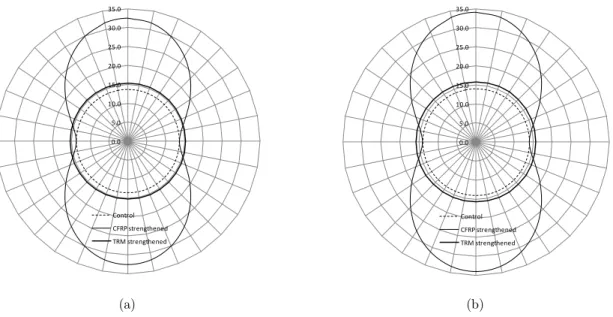
for the strengthened RC slabs of two concrete grades is shown in Figure 12. The variation ofm
is due to the use of single CFRP sheet of unidirectional fibers thus making it orthotropic.(a) (b)
Figure 12: Angular variation of moment capacity of slabs (kNm/m) with CFRP fibers in vertical direction: (a) Concrete grade A; (b) Concrete grade B.
The fibers in the TRM being same in the two orthogonal directions, mƟ is constant. The flexural
capacity of the slab, Pflex, can be calculated based on the yield line analysis as follows (Elstner and
Hognestad, 1956):
3
2
2
/
1
1
8
B
c
m
P
flex (7)in which c is the side length of equivalent square loaded area.
The punching shear strength, Pu1, of the strengthened slab is calculated according to the equa-tion proposed by Mowrer and Vanderbilt (1967) as follows:
0.0 5.0 10.0 15.0 20.0 25.0 30.0 35.0
Control CFRP strengthened TRM strengthened
0.0 5.0 10.0 15.0 20.0 25.0 30.0 35.0
Latin A m erican Journal of Solids and Structures 12 (2015) 1616-1640
flex c c uP
f
bd
f
bd
c
d
P
/
433
.
0
1
/
1
8
.
0
' ' 1
(8)where b is the perimeter of the loaded area.
4.2 Second Peak Load
The reduction in load after the first peak is due to the start of dislodging of truncated cone thus continuous degradation of shearing resistance offered by concrete which becomes more and more dependent on aggregate interlocking. The movement of cone is then resisted by dowel action pro-vided by steel rebars and CFRP / TRM layers which start building up with increase in the mo-vement of cone thereby leading to the formation of second peak in the strengthened slab. The second peak load is thus the algebraic sum of the resistance offered by concrete after the forma-tion of shear cone through aggregate interlocking and dowel acforma-tion provided by steel rebars and CFRP /TRM layers:
d a
u P P
P2 (9)
where, Pd is the shear resistance provided by dowel action of steel rebars and CFRP / TRM
la-yers; Pa is the shear resistance offered by aggregate interlock in concrete which can be estimated
from:
D
b
f
P
a c' o3
(10)where, is the shear strength reduction factor due to crack widening/opening at second peak. The value of is calculated using (Muttoni, 2008).
g g
d
d
d
015
1
75
.
0
(11)where, dg0 is 16 mm and dg is the maximum size of aggregate (= 10 mm in this study);
d
is theLatin A m erican Journal of Solids and Structures 12 (2015) 1616-1640
Hewitt and Batchelor (1975) found the theoretical punching shear strength of RC slabs to be 20% less than the test results which was attributed to the dowel action of the rebars. Regan and Bra-estrup (1985) stated that the dowel action increased the punching shear strength of RC slab by 34%. In this research, the dowel action hypothesis proposed by Millard and Johnson (1984) and Menerey et al. (1996, 1997) have been modified to include the effect of dowel action provided by CFRP / TRM layers:
2 2 1 ' 2 2 ' 1 2
sin
1
2
sin
1
2
1
fu f fu c f y s y c n i i df ds df
f
f
f
A
f
f
f
f
P
P
P
(12)where, fs is the stress in steel rebars at failure;
i is the diameter of rebars embedded in thepunching cone; n is the number of rebars embedded in the punching cone; ff1 is the stress in CFRP / TRM at failure; Af is the cross sectional area of the fibers in CFRP / TRM sheet
em-bedded in the punching cone; Pds is the shear carried by the dowel action of steel rebars; Pdf is
the shear carried by the dowel action of the CFRP/TRM sheets. The above equation shows that a parabolic interaction is assumed between the axial force and the dowel force in the reinforcing bars and fibers of strengthening layers. As the reinforcing bars and fibers of strengthening layers are not at right angle to the punching crack, the dowel contribution is reduced by 50% in the above equation. The stresses in rebars and CFRP /TRM sheet, required in the above equation, can be determined using:
n i si ds sA
P
f
1 2tan
(13) f df fA
P
f
2 1tan
(14)where, Asi is the area of rebars embedded in the punching cone; Vus and Vuf are the punching
loads shared by steel rebars and CFRP / TRM layers, which have been calculated in proportion to their stiffness, thus giving:
f fu s y
d fu f df
f
A
f
A
P
f
A
P
(15) df dds
P
P
Latin A m erican Journal of Solids and Structures 12 (2015) 1616-1640 It is seen from the above equations that the stresses fs and ff1 are dependent on the ultimate shear load, which is not known, thus the calculation requires iterations to be carried out for de-termining the punching load Pd.
4.3 Comparison of Prediction with Experiments
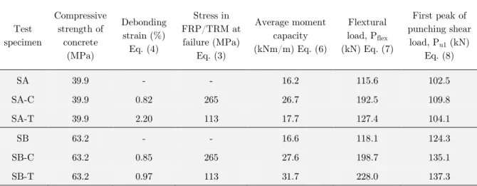
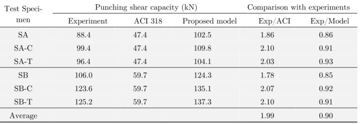
Based on the above formulation, Tables 3 and 4 present detailed calculations of the first and the second peak loads of the slab specimens tested in the current study. The predicted values of the first peak loads are compared with the experimental values in Table 5, whereas the comparison for second peak is done in Table 4. It can be noted from the tables that the proposed analytical models for the first as well as the second peak loads provide reasonably good predictions for the punching capacity of the tested slabs as the average of the ratio Pu exp/Pu model for the first and the second peaks are 0.90 and 1.02 respectively.
The experimental results of the first peak load or the punching capacity are also compared with ACI 318 (2011) equation for the two-way shear strength:
d
b
f
d
b
f
P
c o c oc u ' '
3
1
2
1
6
1
(17)where c is the ratio of the long side to the short side of the column, bo is the perimeter of the
critical section for the punching shear taken at a distance of d/2 from the periphery of the co-lumn. Test specimen Compressive strength of concrete (MPa) Debonding strain (%) Eq. (4) Stress in FRP/TRM at failure (MPa) Eq. (3) Average moment capacity (kNm/m) Eq. (6)
Flextural load, Pflex (kN) Eq. (7)
First peak of punching shear
load, Pu1 (kN) Eq. (8)
SA 39.9 - - 16.2 115.6 102.5
SA-C 39.9 0.82 265 26.7 192.5 109.8
SA-T 39.9 2.20 113 17.7 127.4 104.1
SB 63.2 - - 16.6 118.1 124.3
SB-C 63.2 0.85 265 27.6 198.7 135.1
SB-T 63.2 0.97 113 31.7 228.0 137.3
Latin A m erican Journal of Solids and Structures 12 (2015) 1616-1640 Test speci-men Crack width at second peak,
d
(mm)
Shear strength reduction factor,
Eq. (11)
Shear car-ried by Steel, Pds (kN) Eq.
(12, 16)
Shear car-ried by agg.
Interlock, Pa (kN) Eq. (10)
Shear carried by
fiber, Pdf (kN) Eq.
(12, 15)
Second peak of punching shear load, Pu2 (kN)
Eq. (9)
Exp/ Predicted
SA 9.0 0.12 16.3 8.0 0.0 24.2 0.99
SA-C 0.2 0.67 8.8 44.8 16.9 70.5 0.98
SA-T 3.5 0.25 13.4 16.3 4.4 34.1 1.09
SB 9.0 0.12 20.5 10.0 0.0 30.5 1.08
SB-C 0.2 0.67 11.0 21.2 21.2 89.1 1.05
SB-T 3.5 0.25 9.3 20.5 30.7 60.5 0.97
Average = 1.02
Table 4: Prediction of second peak of punching shear load using proposed model.
Test Speci-men
Punching shear capacity (kN) Comparison with experiments Experiment ACI 318 Proposed model Exp/ACI Exp/Model
SA 88.4 47.4 102.5 1.86 0.86
SA-C 99.4 47.4 109.8 2.10 0.91
SA-T 96.4 47.4 104.1 2.03 0.93
SB 106.0 59.7 124.3 1.78 0.85
SB-C 123.6 59.7 135.1 2.07 0.92
SB-T 125.2 59.7 137.3 2.10 0.91
Average 1.99 0.90
Table 5: Punching shear capacity (First peak) comparison.
Specimen group ID
Energy absorption* (kN-mm)
Control CFRP strengthened
slabs TRM strengthened slabs
SA 786 1306
(66.1%)
959 (22.0%)
SB 1062 1758
(65.5%)
1685 (58.7%)
* Value within brackets is the percentage increase with respect to control.
Latin A m erican Journal of Solids and Structures 12 (2015) 1616-1640 Table 5 shows that ACI equations provide very conservative predictions for the punching shear strength of the tested slabs in comparison to the proposed model. The average ratio Pu exp/Pu ACI
is 1.99 using the ACI 318 (2011) equation compared to 0.90 for the proposed model as given in Table 5. It should be noted that the code equations do not account for the effect of the strengt-hening layers and therefore the provisions of the code are not intended for the strengthened slabs. Thus the proposed model may be adopted for the prediction of the punching shear capacity of FRP and TRM strengthened RC slabs.
5 CONCLUSIONS
The main findings of the study presented in the paper can be summarized as follows:
i) Experimental load-displacement variations show two peak loads in the strengthened slabs and one peak followed by a plateau in the control slabs. Second peak or the plateau corresponds to the combined action of the aggregate interlock and dowel action of the back face rebars and the strengthening layers. The dowel action of the back face rebars and the strengthening layers had no role in ultimate punching load (i.e. first peak load).
ii) Although the strengthened slabs showed nominal increase in the first peak load (9-18%) but there was significant increase in the second peak load (190-276% for the CFRP strengthened slabs; 55-136% for the TRM strengthened slabs) and energy absorption (~66% for CFRP strengthened slabs and 22-56% for TRM strengthened slabs).
iii) An analytical model was also developed for predicting the punching shear strength (first and second peaks) of strengthened slabs. The model agrees reasonably well with the experimental results.
Acknowledgements
The authors gratefully acknowledge the financial grant (No.: ADV 728-02) received from King Abdul-Aziz City for Science and Technology, Saudi Arabia, under National Plan for Science and Technology. Thanks are also extended to the MMB Chair for Research and Studies in Strengt-hening and Rehabilitation of Structures, at the Department of Civil Engineering, King Saud Uni-versity for providing technical support.
References
Abbas, H., Gupta N.K., Alam, M. (2004). Nonlinear response of concrete beams and plates under impact loading. Internatonal ournal of Impact Engineering 30(8-9):1039-1053.
Abdullah, A., Bailey, C.G., Wu, Z.J. (2013). Tests investigating the punching shear of a column-slab connection strengthened with non-prestressed or prestressed FRP plates. Construction and Building Materials 48:1134-1144.
Latin A m erican Journal of Solids and Structures 12 (2015) 1616-1640
Adetifa, B., Polak, M.A. (2005). Retrofit of slab column interior connections using shear bolts. ACI Structural Jour-nal 102(2):268-274.
Alhaddad, M., Siddiqui, N., Abadel, A., Alsayed, S., Al-Salloum, Y. (2012). Numerical investigations on the seismic behavior of FRP and TRM upgraded RC exterior beam-column joints. Journal of Composite for Construc-tion 16(3):308–321.
Al-Rousan, R., Issa, M., Shabila, H. (2012). Performance of reinforced concrete slabs strengthened with different types and configurations of CFRP. Composite Part B: Engineering 43(2):510–521.
Al-Salloum, Y.A., Siddiqui, N.A., Elsanadedy, H.M., Abadel, A.A., Aqel, M.A. (2011). Textile-reinforced mortar (TRM) versus FRP as strengthening material of seismically deficient RC beam-column-joints. Journal of Composite for Construction 15(6):920–933.
ASTM. (1985). Method for tensile strength of hydraulic cement mortars. C190-85, West Conshohocken, PA.
ASTM. (2002). Standard test method for compressive strength of hydraulic cement mortars (Using 2-in. or [50-mm] Cube Specimens). C109/C109M-02, Annual book of ASTM standards, Vol. 4.01, West Conshohocken, PA.
ASTM. (2012). Standard test method for compressive strength of cylindrical concrete specimens. C39/C39M.,Annual Book of ASTM Standards, 04.02, West Conshohocken, PA
ASTM. (2012). Standard test methods and definitions for mechanical testing of steel products. A370-12, West Con-shohocken, PA.
Binici, B., Bayrak, O. (2003). Punching shear strengthening of reinforced concrete flat plates using carbon fiber rein-forced polymers. Journal of Strucural Engineering 129(9):1173–1182.
Cantwell, W.J., Smith, K., (1999). The static and dynamic response of CFRP-strengthened concrete structures. Journal of Material Scince Letters 18:309-310.
Chen, C.C., Li, C.Y. (2000). Experimental study on the punching shear behaviour of RC slabs. Proc., International Workshop on Punching Shear Capacity on RC Slabs, Royal Institute of Technology, Stockholm, Sweden 415-422.
Chen, C.C., Li, C.Y. (2005). Punching shear strength of reinforced concrete slabs strengthened with glass fiber-reinforced polymer laminates. ACI Structural Journal 102(4):535-542.
Cheng, C., Chung, L. (2005). Punching shear strength of reinforced concrete slabs strengthened with glass fiber-reinforced polymerlaminates. ACI Structural Journal 102(4):535-542.
Ebead, U., Marzouk, H. (2002). Strengthening of two-way slabs using steel plates. ACI Structural Journal 99(1):23–
30.
Ebead, U., Marzouk, H. (2004). Fiber-reinforced polymer strengthening of two-way slabs. ACI Structural Journal 101(5), 650–659.
El-Salakawy, E., Soudki, K.A., Polak, M.A. (2004). Punching shear behavior of flat slabs strengthened with fiber reinforced polymer laminates. Journal of Composite for Construction 8(5):384–92.
Elsanadedy, H.M., Abbas, H., Al-Salloum, Y.A., Almusallam, T.H. (2014). Prediction of intermediate crack debonding strain of externally bonded FRP laminates in RC beams and one-way slabs. Journal of Composite for Construction. DOI: 10.1061/(ASCE)CC.1943-5614.0000462. 18(5):04014008.
Latin A m erican Journal of Solids and Structures 12 (2015) 1616-1640 El-Sayed, A.K. (2014). Strengthening of structurally damaged wide shallow RC beams using externally bonded CFRP plates. Latin American Journal of Solids and Structures 11(6):946-965.
Elstner, R.C., Hognestad, E. (1956). Shearing strength of reinforced concrete slabs. ACI Journal Proceeding 53(2):29-58.
Erki, M.A., Heffernan, P.J. (1995). Reinforced concrete slabs externally strengthened with fibre reinforced plastics materials. Proceeding of 2nd International Symposium on Non-Metalic FRP Reinforcement for Concrete Structures (FRPRCS-2), L. Taerwe, ed., E & FN Spon, London, 509–516.
Esfahani, M., Kianoush, M., Moradi, A. (2009). Punching shear strength of interior slab–column connections strengthened with carbon fiber reinforced polymer sheets. Engineering Structure 31(7):1535-1542.
Farghaly, A.S., Ueda, T. (2011). Prediction of punching shear strength of two way slabs strengthened externally with FRP sheets. Journal of Composite for Construction 15(2):181–193.
Gardner, N.J., Huh, J., Chung, L. (2002). Lessons from the sampoong department store collapse. Cement and Con-crete Composite 24(6):523-529.
Ghali, A., Sargious, M.A., Huizer, A. (1974). Vertical prestressing of flat plates around columns. Shear in reinforced concrete, ACI SP, SP-42, 2: 905–920.
Harajli, M.H., Soudki, K.A. (2003). Shear strengthening of interior slab-column connections using carbon fiber-reinforced polymer sheets. Journal of Composite for Construction 7(2):145–153.
Hassanzadeh, G., Sundqvist, H. (1998). Strengthening of bridge slabs on columns. Nordic Concrete Research: The Nordic Concrete Federation, publication no. 21; 1998. Paper no. 2.
Hewitt, B.E., Batchelor, BdeV. (1975). Punching shear strength of restrained slabs. Journal of Structural Division 101(9):1837–53.
Kim, D., Sebastian, W.M. (2002). Parametric study of bond failure in concrete beams externally strengthened with fiber reinforced polymer plates. Magazine of Concrete Research 54 (1):47-59.
Koppitz, R., Kenel, A., Keller, T. (2013). Punching shear of RC flat slabs – Review of analytical models for new and strengthening of existing slabs. Engineering Structural 52:123-130.
Limam O., Nguyen, V.T., Foret G. (2005). Numerical and experimental analysis of two-way slabs strengthened with CFRP strips. Engineering Structure 27(6): 841-845
Malvar, L.J., Warren, G.E., Inaba, C.M. (2000). Large scale tests on Navy reinforced concrete pier decks strength-ened with CFRP sheets. Proceeding of 3rd International Conference on Advanced Composite Materials in Bridges and Structures, ACMBS-III, Canadian Society for Civil Eng., Montreal, Quebec, 497-504.
Meier, U. (1992). Carbon fibre-reinforced polymers, Modern materials in bridge engineering. Structural Engineering International 2(1):7-12.
Menerey, Ph., (1996). Analytical computation of the punching strength of reinforced concrete. ACI Structural Jour-nal 93(5):503–11.
Menerey, Ph., Walther, R., Zimmermann, Th. (1997). Simulation of punching failure in reinforced-concrete struc-tures. Journal of Structural Engineering 123(5):652–9.
Latin A m erican Journal of Solids and Structures 12 (2015) 1616-1640
Mowrer, R.D., Vanderbilt, M.D. (1967). Shear strength of light-weight aggregate reinforced concrete flat plates. ACI Journal Proceeding 64(11):722-729.
Muttoni, A. (2008). Punching strength of reinforced concrete slabs without transverse reinforcement. ACI structural Journal 105(4):440-450.
Oh, H., Sim, J. (2004). Punching shear strength of strengthened deck panels with externally bonded plates. Composi-te Part B 35(4):313–321.
Papanicolaou, C., Triantafillou, T., Papantoniou, I., Balioukos, C. (2009). Strengthening of two-way reinforced con-crete slabs with textile reinforced mortars (TRM). Proceeding of 4th colloquium on textile reinforced structures (CTRS4), Dresden. Technische Universität Dresde.
Peled, A., Mobasher, B. (2007). Tensile Behavior of Fabric Cement-Based Composites: Pultruded and Cast, ASCE Journal of Materials in Civil Engineering 19(4):340-348.
Arboleda, D., Loreto, G., De Luca, A., Nanni, A. (2012). Material characterization of fiber reinforced cementitious matrix (FRCM) composite laminates. Proceedings of 10th International Symposium on Ferrocement and Thin Rein-forced Cement Composite, Havana, Cuba, October 12-17.
RILEM TC 201TRC (2006). Textile Reinforced Concrete State of the art Report of RILEM TC.
Regan, P.E., Braestrup, M.W. (1985). Punching shear in reinforced concrete. Bulletin d’Information 168, Comitte
Euro-International du Beton.
Reinhartd, H.W., Walraven, J.C. (1982). Crack in concrete subject to shear. Journal of Structural Divison 108(ST1):207–224.
Rochdi, E.H., Bigaud, D., Ferrier, E., Hamelin, P. (2006). Ultimate behavior of CFRP strengthened RC flat slabs under a centrally applied load. Composite Structures 72(1):69–78.
Sharaf, M., Soudki, K., Van Dusen, M. (2006). CFRP strengthening for punching shear of interior slab–column con-nections. Journal of Composite for Constuction 10(5):410–418.
Siddiqui, N.A. (2011). Experimental investigation of RC beams strengthened with externally bonded FRP compo-sites. Latin American Journal of Solids and Structures 6(4):343-362.
Soudki K., El-Sayed A.K., Tim Vanzwol, T. (2012). Strengthening of concrete slab-column connections using CFRP strips. Journal of King Saud University- Engineering Science 24:25–33.
Triantafillou, T.C., Papanicolaou, C.G. (2006). Shear strengthening of reinforced concrete members with textile reinforced mortar (TRM) jackets. Material and Structure 39(1):93–103.
Triantafillou, T.C., Papanicolaou, C.G., Zissimopoulos, P., Laourdekis, T. (2006). Concrete confinement with textile-reinforced mortar jackets. ACI Structural Journal 103(1):28–37.
Van Zowl, T., Soudki, K. (2003). Strengthening of concrete slabcolumn connections for punching shear. Technical Report, University of Waterloo, Waterloo, Canada.