ABSTRACT: The objective of this paper is to analyze the inluence of speciic laser system parameters on the microstructure of the ring formation process on the hard metal tool’s surface. The parameters analyzed were: working distance, incident beam power and tool surface treatment, lank and rake. The microstructures were analyzed with regard to its diameter and depth by an optical 3-D surface metrology instrument. The analyses were made by comparing the ring’s process formation with the dimples’ process formation, a well-known process called ablation. The results show that the ring’s diameter is increased by increasing incident beam power or the distance of the laser beam’s focus for both surfaces. In addition, increasing the working distance decreases the ring’s depth for both surfaces.
KEYWORDS: Surface inishing, Pulsed lasers, Ablation, Microstructure.
Effect of Solid-State Laser Parameters on
the Surface’s Topography Formation During
Texturization of Hard Metal Cutting Tools
Patrícia Helena de Oliveira Teixeira1,2, Adriano Gonçalves dos Reis1,2, Andreas Janssen3
INTRODUCTION
One of the biggest concerns of industry is the improvement of manufacturing eiciency in order to obtain minimization of production costs, maximization of production rate and maximization of production accuracy, etc.. In aeronautic industry, these are main concerns as well, especially with the prediction that the number of new airplanes will grow by more than 27.000 until 2025 compared to 2005 (Klocke et al., 2012). his prediction leads to an economic pressure on the aviation industry manufacturers, and the search for optimization in the manufacturing processes becomes necessary. For the aircraft components construction, several manufacturing processes are used, and machining stands between the most applied ones. According to Aurich et al. (2011), during machining process, high mechanical and thermal loads occur at the cutting tool, causing tool failure. Due to this, optimization at the cutting tool represents an advantageous possibility. Cutting tools have been optimized by improvements of cutting tool material, coating system and tool macrogeometry. however, cutting tools with higher qualities regarding material removal rates, chip removal of hard-to-machine materials and tool life are each day more requested.
1.Faculdade de Tecnologia de São José dos Campos – São José dos Campos/SP – Brazil 2.Instituto Tecnológico de Aeronáutica – São José dos Campos/SP – Brazil
3.Fraunhofer Institute for Production Technology – Aachen – Germany.
Author for correspondence: Patrícia Helena de Oliveira Teixeira | Faculdade de Tecnologia de São José dos Campos | Avenida Cesare Mansueto Giulio Lattes, s/n, Eugênio de Melo | CEP: 12.247-014 – São José dos Campos/SP – Brazil | Email: [email protected]
Figure 1. Physical mechanisms in SP and USP laser ablation (Janssen, 2012).
Absorption
Absorption Heat
conduction Melting Evaporation
Evaporation
Super fast heating Vapor
Vapor Vapor
Vapor Melt Melt Melt
Isothermal lines Work piece Laser beam
Laser beam
Work piece SP laser
ablation
USP laser ablation
Melt ejection
1
1 2
3 4 5
2
LASER-BASED CUTTING TOOL
PRODUCTION
Looking on technical and mechanical assemblies, contact surfaces mainly determine the performance of systems in terms of being the interfaces where energy is transferred, converted and dissipated. he preparation of cutting tools using laser radiation is a useful improvement compared to the use of conventional techniques for optimization of these surfaces. Laser processing is a very powerful technique for manufacturing modiication of deined cutting tool geometries. It is a non-contacting, wear free technique and not only ofers highest lexibility due to the fact that the beam can be moved very fast by optical devices, but also provides excellent control of shape and size of microstructures, and, furthermore, a process relatively clean to the environment (Etsion, 2004).
According to Aurich et al. (2011), certain morphology modifications of contacted surfaces on cutting tools can improve tool performance. The so called laser-manufactured “micro-dimples” are microstructures already analyzed in recent research (Scaraggi et al., 2013; Kim et al., 2012). The fundamental formation process is the well-known process of laser ablation, which forms single ablation cavities by single laser pulses or complex superposition of many pulses. According to Meijer et al. (2002), the term “ablation” relates to the effect of vaporizing irradiated material by incident laser beam. According to Poprawe (2004), laser radiation is used as a working tool to structure matter by ablation, defining the lateral precision. For this reason, laser radiation is projected by objectives onto the surface, thereby being formed to a specific spatial intensity distribution. Ablation is a process strongly dependent of pulse duration and wavelength, and it can occur by two main principles: short pulse and ultra-short pulse laser ablation. The type of ablation process determines the finishing quality of the ring (Poprawe, 2004). The characteristic of the ablation process — short or ultra-short laser ablation — is determined by the pulse duration, as shown in Fig. 1.
When the pulse duration is longer than 1 nanosecond (1 ns = 10-9 s), the process is called short pulse laser ablation and its major characteristic is the signiicant amount of material being removed from the irradiated area in liquid phase. At this process, there is a high absorption of laser energy in the vaporized material along the duration of one pulse. When the pulse duration is smaller than 1 ns, the heating mostly takes
place ater the period of time of pulse duration and the process is called ultra-short pulsed laser. In opposite to pure ablation process, the formation pro cess of rings is still not widely studied. During the rings’ formation, there is just a slightly melting of surface material and very few of it is evaporated. Accord ing to Cabeza et al. (2012), the morphology at the surface can be characterized as solidiied melted zone combining ine grain appearance and waves in the radial direction.
Janssen (2012) introduced the possible benefits of such microstructures manufactured by laser ablation on highly stressed parts. Based on this, in the present context, the functionalizing aims of three technological benefits for the cutting process are:
• An optimized surface topography enables the reduction of friction and cutting forces in the regime of direct tool-work piece contact.
• he lubrication shall be improved, leading then, to a reduction of tool’s wear and hence to increased tool’s life time. Alternatively higher cutting velocities can be applied without decreased life time.
• For several applications, it can be assumed that the current laser process allows supplying a higher surface quality on the treated work piece and thus increases an qualitative process output.
Figure 2. (a) regular dimples, distributed on the surface, and (b) textured composed of overlapping dimples, completely covering the surface (Klocke and Schmitt, 2012).
100 μm
50 μm
(a) (b)
dimples and rings. he diference between both microstructure is that, unlike dimples, which allow some parts of the original tool material to be in contact with the workpiece, in the ring’s microstructure, the tool surface in contact with the workpiece is completely modiied by laser texturing. he present work aimed analyzing the formation process of ring’s microstructure subjected to the main process parameters.
Due to positive results considering tool life, high material removal rates etc., obtained in previous works, the laser texturing process becomes an important tool in the cutting tool preparation ield. Research about the laser functions and operation methods is necessary in order to deine a behavior profile of laser parameters in obtaining textured surfaces, especially when these textured surfaces are now starting to be used, as for the case of ring’s structures.
METHODOLOGY – STUDY ON RING’S
FORMATION
he work was performed at the Fraunhofer Institute for Production Technology (IPT), a research laboratory, localized in the city of Aachen, Germany. For texturing experiments, a custom-designed laser structuring machine has been utilized, which was installed within former research projects.
EXPERIMENTAL SETUP
Based on industrial as well as research demands, the machine has been designed based on a 5-axis milling machine, which was adapted by implementation of an entire nanosecond laser ablation system including laser source, transportation iber and
laser scanner. With this machine, a real 3-D laser structuring process is possible by means of using 8 axes (5 machine, 3 optical, 1 virtual). The laser source used was the Ytterbium pulsed fiber laser YLPM-1-A4-20-20, from IPG Laser. Regarding to its conigurations, the laser presents an extended pulse repetition rate from 1.6 to 1,000 kHz, selectable pulse durations (4, 8, 14, 20, 30, 50, 100 and 200 ns) and maximum peak power of 15 kW. he tool material used was cemented carbide from the group K (red), a conventional tungsten carbide grade. he material was chosen by the fact that the cemented carbide is one of the most utilized cutting tool materials today and the group derived from tungsten carbide is most readily employed.
he tool utilized was manufactured by SECO, from the model TNMA160404F, 410, 5µ. It was specially developed for speciic applications in Fraunhofer IPT. It presents the lank surface specially treated but the rake surface is free of any surface treatment, which means the laser hits a hard metal WC-Co surface.
EXPERIMENTAL APPROACH
It has to be considered that the formation of the desired rings is based on a reduced ablation process. he process parameters are selected for causing a slight melt formation on the surface and subsequent evaporation of a very small amount of heated material. In regular laser ablation, this amount is decreased to the achievable maximum, since it enables high material removal and thus ablation rate. Here, the evaporation is only utilized to evolve a back pressure on the molten material. he molten layer, however, is only several hundred nanometers in thickness, thus the re-solidiication takes place very fast, leading to the formation of rings in terms of “frozen liquid structures”. For a better understanding, it can be imagined a stone being thrown in the water, and then it immediately solidiies in the irst ring’s formation.
Among the existing process parameters, which define a laser process, this work focused on the influence of two main process parameters: laser power and working distance. These process parameters control the process. However, they are no real process quantities. In the following, the meaning of these two parameters is described.
each pulse from the following one is commonly several thousand times higher than the pulse duration. hus, the average power PL can be several ten Watts only, while the pulse peak power PLM, which is the absolute power within the pulse duration, can reach many thousand Watts.
To meet this fact, it is common in the ield of SP and USP laser ablation processing to give not the laser output power but the intensity I or the luency F, while the intensity gives the energy coupled into a unit area per time (Eq. 1):
Figure 3. Beam propagation and spot size variation (Janssen, 2012).
Because the rake and the lank surfaces passed by diferent treatments, each surface has, therefore, diferent properties. For this reason, both were laser-treated and the laser parameters’ inluence was also investigated under the circumstances of the two material diferences.
he surface measurements — diameter and depth — of the structured tool were made by the surface measurement device Alicona Ininite Focus Real 3-D — an optical 3-D surface metrology instrument. It automatically measures the complete structure of a surface (form, roughness and contour, for example).
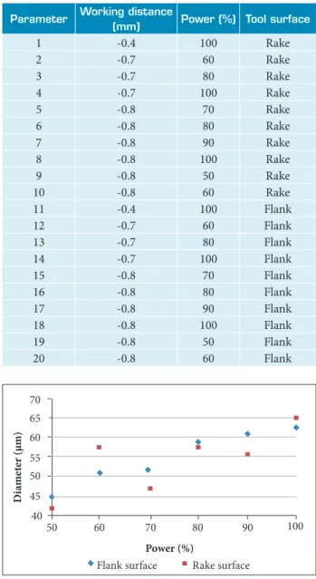
For the tests, 20 diferent laser parameter combinations were deined, as shown in Table 1, in order to achieve diferent diameters and depth in the rings’ structure.
RESULTS AND DISCUSSION
DIAMETER ANALYSISThe first results were obtained by varying the power percentage. The working distance was kept in -0.8 mm. The graph from Fig. 4 shows the diameter’s behavior through the variation of the power percentage. The increment in diameter presents a tendency of growth when the incident beam power is increased. In the flank surface, which received the special surface treatment, the increment in the diameter is constant and it occurs in a smoother behavior. On the other hand, for the rake surface, where there is no treatment, the increasing in the diameter occurs through an irregular manner.
In the second analysis, the power was kept constant at 100%, while the working distance was varied. he graph from Fig. 5 shows a comparison of the diameter’s behavior between the two surfaces tested.
where EP is the pulse energy; A is the focal spot area and
tL is the pulse duration.
he luency gives the energy coupled into a unit area without time information, according to Eq. 2.
his is more common in USP laser processing, where efects can be interpreted independently from the pulse duration. In the project around this work, a laser has been utilized not only in the SP regime but it is additionally capable of emitting pulses of variable pulse duration. he pulses can be selected between 4 and 200 ns. Based on preliminary investigations, the pulse duration was kept constant at 100 ns.
In the present work’s evaluations, the parameter PL is given. So, the variables A and EPcould be varied independently.
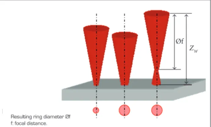
he working distanceisthe distance between focusing lens and work piece. To understand the meaning, Fig. 3 shows the beam propagation of a laser beam. By varying the working distance zW, the spot diameter can be adjusted, ofering the possibility to control the focal spot size. his is limited due to the laser beam’s propagation proile, which is the intensity distribution within a ixed z-plane.
Having these two control parameters, laser power and working distance, one is able to inluence the ring formation in terms of varying the irradiated and the impinged energy per area. he main characteristics which are evaluated concerning the ring’s formation are their diameter and depth. he arrangement of rings in a pattern can be easily done by adapting the program which controls the tool path for the laser scanner mirrors and thus is not investigated in this work.
Øf
ZW
Resulting ring diameter Øf f: focal distance.
(1)
(2)
I =
F =
Ep
Ep A . tL
Figure 4. Diameter’s behavior through power percentage variation.
Figure 5. Diameter’s behavior through working distance variation.
Figure 6. Images of ring’s texture for different power percentage values on lank tool surface.
Focus position is one of the most critical process parameters and directly affects the remaining geometry after material removal (Bordatchev and Nikumb, 2006).
On both tool surfaces, the decrease in laser focus distance caused an increase in the spot’s diameter, which was the result expected according to the situation presented in Fig. 3.
Figures 6 and 7 show the result of the laser surface treatment on both tool surfaces.
Althought increasing the power increases the diameter’s values, it also causes other effects on the rings, as it can be seen in Figs. 6 and 7. The images show that the tests where the power percentage was higher presented less precision
Parameter Working distance
(mm) Power (%) Tool surface
1 -0.4 100 Rake
2 -0.7 60 Rake
3 -0.7 80 Rake
4 -0.7 100 Rake
5 -0.8 70 Rake
6 -0.8 80 Rake
7 -0.8 90 Rake
8 -0.8 100 Rake
9 -0.8 50 Rake
10 -0.8 60 Rake
11 -0.4 100 Flank
12 -0.7 60 Flank
13 -0.7 80 Flank
14 -0.7 100 Flank
15 -0.8 70 Flank
16 -0.8 80 Flank
17 -0.8 90 Flank
18 -0.8 100 Flank
19 -0.8 50 Flank
20 -0.8 60 Flank
Table 1. Laser parameter variation.
in the diameter’s shape. In both surfaces, it is possible to notice that the laser ring’s edges become less defined as the power grows.
his phenomenon can be explained by the texturing laser mechanism. Since the utilzed laser pulses where set to 100 ns in duration, the laser matter interaction time is long enough to enable a large amount of material being melted whithin the pulse duration. Evaporating material evolves a huge back pressure on the underlying material, which, in this case, is in melted state and thus can be expelled to the outer region of the irradiation zone. 55
60 65 70
50
45
40
Power (%)
Flank surface Rake surface
Di
ame
te
r (μm)
50 60 70 80 90 100
50%
80%
60%
90%
70%
100%
50μm 50 60 70
40
30
20
Working distance (mm)
Flank surface Rake surface
Di
ame
te
r (μm)
Di
ame
te
r (μm)
Distance of the focus beam (mm)
Flank surface Rake surface -0.9 -0.8 -0.7 -0.6 -0.5 -0.4
50 60 70
40
30
20
-0.9 -0.8 -0.7 -0.6 -0.5 -0.4
Figure 8. Graph of depth’s behavior through power variation on the lank and rake tool surfaces.
Figure 9. Ablated depth for different luencies. Figure 7. Images of ring’s texture for different power
percentage values on rank tool surface. 50μm
DEPTH ANALYSIS
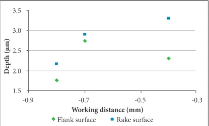
he second microstructure parameter analyzed was the depth of the rings. For this analysis, the same variation of laser parameters used for diameter’s analysis was used.
Figure 8 shows the dependency of the resulting ring’s depth on laser’s power. he working distance was kept constant at 0.8 mm. Figure 8 also shows that, for the lank surface, there is a slight decrease in depth when the power increases. It is also possible to see, for the rake surface, that the depth slightly increases as well, when the power percentage increases.
In previous researches, Dumitru et al. (2004) presented a study where one could observe that higher incident luencies generated larger ablation rate. In other words, it means that with/ when increasing the laser power, the depth will also increase.
However, the same behavior is not seen in either the studied cases. Changing the power in the rings’ formation does not present the same correlation as in the pure ablation process, when analyzing the depth of the microstructure.
Caused by the formation principle, described before, the resulting surface ater the meltiwng is not lat, but with peaks and valleys, created by the solidiication of the thermally driven motion of molten material. his surface characteristic makes it diicult to deine a right spot to measure the depth. In addition, the depth proile of the rings is just slightly above the order of the original surface’s roughness, which also complicates the depth’s determination.
For the second analysis of the microstructure’s depth, the power was kept constant at 100%, while the working distance was varied. he graph from Fig. 9 shows a comparison of the depth behavior between the two tested surfaces. In the rake surface, it is seen that when increasing the working distance, the depth
also decreases. In the lank surface, however, this behavior is not constant, although, in general, there is the decrease of the depth with the increase of the working distance.
It is known that, when the laser beam operates in its exact focus, the incident intensity (and also luency) in the irradiated surface’s area is maximal. For a pure ablation processes, the bigger the incident intensity, the bigger is the ablation rate during the process, which leads to a bigger depth. However, the intensity hitting the surface is decreased when the laser beam works out of its focus. hus, the manufacturing of the ring’s texture needs to be conducted in a defocused range in order to ind the optimum intensity. he latter is found when the amount of evaporated material is just suicient to force the molten material to form a ring exhibiting the desired shape.
CONCLUSION
Based on this investigation, the following conclusions could be drawn:
3.5
3.0
2.5
2.0
1.5
-0.9 -0.7 -0.5 -0.3
Working distance (mm)
Flank surface Rake surface
D
ep
th (μm)
3.5
3.0
2.5
2.0
1.5
Power (%)
Flank surface Rake surface
D
ep
th (μm)
40 50 60 70 80 90 100
50%
80%
60%
90%
70%
REFERENCES
Aurich, J.C., Zimmermann, M. and Leitz, L., 2011, “The Preparation of Cutting Edges Using a Marking Laser”, Production Engineer, Vol. 5, No.1, pp. 17-24. doi: 10.1007/s11740-010-0275-9
Bordatchev, E. and Nikumb, S.K., 2006, “Effect of Focus Position on Informational Properties of Acoustic Emission Generated by Laser-Material Interactions”, Applied Surface Science, Vol. 253, No. 3, pp. 1122-1129. doi: 10.1016/j.apsusc.2006.01.047
Cabeza, M., Castro, G., Merino, P., Pena, G. and Román, M., 2012, “Laser Surface Melting: a Suitable Technique to Repair Damaged Surfaces Made in 14 Ni (200 grade) Maraging Steel”, Surface and Coatings Technology, Vol. 212, pp. 159-168. doi:10.1016/j.surfcoat.2012.09.039
Dumitru, G., Romano, V., Weber, H.P., Gerbig, Y., Haefke, H., Bruneau, S., Hermann, J. and Sentis, M., 2004, “Femtosecond Laser Ablation of Cemented Cabides: Properties and Tribological Applications”, Applied Physics A – Materials Science & Processing, Vol. 79, No. 3, pp. 629-632. doi: 10.1007/s00339-004-2675-1
Etsion, I., 2004, “Improving Tribological Performance of Mechanical Components by Laser Surface Texturing”, Tribology Letters, Vol. 17, No. 4, pp. 733-737. doi: 10.1007/s11249-004-8081-1
Janssen, A., 2012, “Laserstrukturieren senkt Reibung hochbelasteter Serienteile”, Maschinenmarkt, Vol. 11.
Kim, B.S., Chung, W.Y., Rhee, M. and Lee, S., 2012, “Studies on the Application of Laser Surface Texturing to Improve the Tribological Performance of AlCrSiN - Coated Surfaces”, Metals and Materials
International, Vol. 18, No. 6, pp. 1023-1027. doi: 10.1007/ s12540-012-0483-2
Klocke, F., Gierlings, S., Adams, O., Aerbach, T., Kamps, S., Veselovac, D., Eckstein, M., Kirchheim, A., Blattner, M., Thiel, R. and Kohler, D., 2012, “New Concepts of force measurement systems for speciic machining processes in aeronautic industry”, Proceedings of the 5th Conference on High Performance Cutting.
Klocke, F. and Schmitt, R., 2012, “Surface conditioning and texturing of cutting tools for the optmization of machining processes”. Proceedings of the 3rd International Meeting of Brazilian-German Collaborative Research Initiative on Production (BRAGECRIM), Aachen, Germany.
Meijer, J., Du, K., Gillner, A., Hoffmannc, D., Kovalenkod, V.S., Masuzawae, T., Ostendorfc, A., Poprawec, R. and Schulzc, W., 2002, “Laser Machining by Short and Ultrashort Pulses, State of Art and New Opportunities in the Age of the Photons”, CIRP Annals - Manufacturing Technology, Vol. 51, No. 2, pp. 531-550. doi:10.1016/S0007-8506(07)61699-0
Poprawe, R., 2004, “Lasertechnik für die Fertigung”, Springer, Heidelberg, Germany, 526p.
Scaraggi, M., Mezzapesa, F.P., Carbone, G., Ancona, A. and Tricarico, L., 2013, “Friction Properties of Lubricated Laser-Microtextured-Surfaces: An Experimental Study from Boundary- to Hydrodynamic-Lubrication”, Tribology Letters, Vol. 49, No. 1, pp. 117-125. doi: 10.1007/s11249-012-0045-2
• Increasing the laser power or the distance of the laser beam focus from the surface led to an increase in the rings’ diameter on the lank and rake surface due to enhanced thermal afection of the surface’s material. hese results are in agreement with the results for the laser ablation process.
• he variation in the incident power beam generated diferent results in the microstructure’s depth of each tested surface. his diference was explained by the process of ring formation and by the supericial melting in the surface’s material caused by the laser. he behavior of the ring’s structural formation is not the same as the phenomenon of ablation.
• he variation in the working distance caused the same result in depth of both studied surfaces. Increasing the
working distance caused the decrease on the ring’s depth, which corresponds to the results of the laser ablation process.
Further studies are required to evaluate the tribological performance of such ring’s textures on the desired application.