Abstract
In this paper, free vibration analysis of rotating functionally graded cylindrical shells with orthogonal stiffeners is presented. Based on Love’s first approximation theory and smeared stiffeners technique, the governing equations of motion which take into account the effects of initial hoop tension and also the centrifugal and Coriolis forces due to rotation are derived. The influence of the power law index, the stiffener’s height-to-width ratio, the circumferential wave numbers, the shell length-to-radius ratio, and the shell radius-to-thickness ratio on the natural frequencies of the simply supported rotating stiffened functionally graded cylindrical shell are investi-gated. To validate the present analysis, comparisons are made with those available in the literature for particular cases; very good agreements are achieved.
Keywords
Natural frequency,rotating, functionally graded material, vibration analysis, cylindrical shell, orthogonal stiffeners.
Vibration Analysis of Rotating Functionally Graded
Cylindrical Shells with Orthogonal Stiffeners
1 INTRODUCTION
Functionally graded materials (FGMs) are a new class of material in which the material properties are varied continuously along a certain dimension of the structure. Typical FGMs are made from a mixture of ceramic and metal. The thermal resistance of the material is increased due to low ther-mal conductivity of the ceramic and the lack of toughness of ceramics is eliminated by using the metal. Hence, the main applications of FGMs have been in high-temperature environments. Func-tionally graded cylindrical shells are used in many industrial applications, such as aerospace, me-chanical and nuclear engineering.
The vibration of non-rotating functionally graded cylindrical shells has been studied extensively for many years. Loy et al. (1999) used Rayleigh-Ritz methodto analyze free vibration of functionally graded cylindrical shells based on Love’s shell theory. They investigated the effects of the
constitu-Tran Minh Tu a Nguyen Van Loi b
a National University of Civil
Engineer-ing, 55 Giai Phong Road, Ha noi, Viet nam
E-mail address: [email protected]
b National University of Civil
Engineer-ing, 55 Giai Phong Road, Ha noi, Viet nam
E-mail address:
http://dx.doi.org/10.1590/1679-78252934
ent volume fractions and the configurations of the constituent materials on the natural frequency. Pradhan et al. (2000) presented the vibration characteristics of functionally graded cylindrical shells with various boundary conditions using Rayleigh method. The effect of boundary conditions and volume fractions on the natural frequency of the functionally graded cylindrical shell was studied. Li et al. (2010) used Flügge’s shell theory to study the free vibration of a simply supported three-layer circular cylindrical shell with the inner and the outer layer made of the same homogenous material and the functionally graded middle layer. Vel (2010) presented an exact elasticity solution for the free and forced vibration of functionally graded cylindrical shells.
Structures such as gas turbine engines, electric motors, and rotor systems usually operate under rotation with constant angular velocities. In contrast with non-rotating cylindrical shells, studies on the vibration of rotating cylindrical shells have been sparse. Chen et al. (1993) applied the finite element method for vibration analysis of isotropic high rotating cylindrical shells. The general equa-tions with consideration of Coriolis acceleraequa-tions and large deformation were established by the method of linear approximation. Based on Sanders’s shell theory, Sun et al. (2012) presented free vibration analysis of thin rotating isotropic cylindrical shells with various boundary conditions using the Fourier series expansion method. Lam and Loy (1994) studied the vibrations of thin rotating laminated cylindrical shells based on Love’s first approximation theory. The effects of the thickness-to-radius ratio, the length-thickness-to-radius ratio and the lamination angle on the fundamental frequency were presented. Lam and Loy (1995) continued their study on the vibration characteristic of rotat-ing laminated cylindrical shells usrotat-ing four common thin shell theories: Donnell’s, Flugge’s, Love’s, and Sanders’ shell theories. The free vibration of thick rotating cross-ply laminated composite cylin-drical shells was studied by Lam and Qian (1999) based on the first-order shear deformation shell theory. Analytical solutions were presented, and frequency characteristics of thin and thick shells were investigated with respect to the variations of rotating speeds, circumferential wave numbers, and length-to-thicknessratio. The effect of transverse shear deformation was also emphasized. The natural frequency of rotating functionally graded cylindrical shells was calculated by Xiang et al. (2012). Theoretical formulation were established based on Love’s first approximation theory; and the effects of the power law index, the wave numbers and the thickness-to-radius ratio on the natu-ral frequency of rotating functionally graded cylindrical shell were carried out. Using Love’s shell theory, Loy et al. (1999) analyzed frequency characteristics of the functionally graded cylindrical shell, parametric studies were numerically investigated.
To the best of the authors’ knowledge, there is no published research in the literature conducted on the free vibration analysis of the rotating stiffened FG cylindrical shells. Thus, in this paper, based on Love’s first approximation theory and smeared stiffeners technique, the vibration analysis of rotating functionally graded cylindrical shell with orthogonal stiffeners is presented. In this study, the governing equations of motion are developed by using smeared stiffeners technique and taking into account the effects of centrifugal and Coriolis forces. The shell is made from functionally graded material and the stiffener from the isotropic material. The presented analysis is verified by compar-ing the numerical results with those in available literature. The effects of the rotatcompar-ing speed, the power law index, the stiffener’s height-to-width ratio, the circumferential wave numbers, the shell length-to-radius ratio, and the shell radius-to-thickness ratio on the natural frequency of the simply supported rotating stiffened cylindrical functionally graded shell are studied.
2 FORMULATION
2.1 Functionally Graded Material
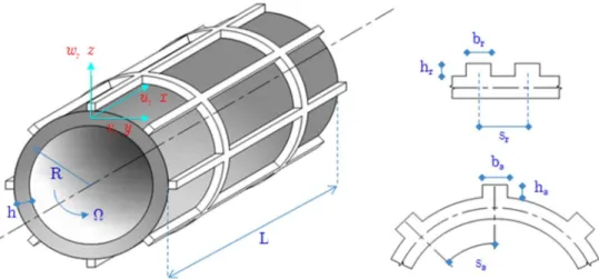
Consider a functionally graded cylindrical shell with orthogonal stiffeners rotating about its horizon-tal axis at a constant angular velocity W as shown Fig. 1, where R L, , and h are the radius, length, and thickness of the shell respectively. The depth of the stringer and ring are denoted by hs
and hr, respectively, and corresponding widths are denoted by bs and br, respectively. The
dis-tances between the stringers, rings are denoted by ss and sr. The number of stringers is ns, andthe
number of rings is nr. Subscripts
(
s r,)
indicate the axial (stringer) and circumferential (ring)stiffeners, respectively. The origin of the coordinate system is located on the edge of the shell, the arbitrary point in the mid-surface is taken by the axial, circumferential and radial axes
(
x, , q z)
. The components of the displacement field in this coordinate system are u in the x, v in the q and win the z-direction. Young’s modulus, mass density, and Poisson’s ratio of stiffeners are0, , 0 0
E r n . The materials properties are assumed to be graded in the thickness direction and vary according to power law as follow:
1 2 2
1
( ) ( )
2 p z
E z E E E
h
æ ö÷ ç
= - çç + ÷÷÷ +
è ø
1 2 2
1
( ) ( )
2 p z z
h
r = r -r æççç + ö÷÷÷÷ +r
è ø
1 2 2
1
( ) ( )
2 p z z
h
n = n -n æççç + ö÷÷÷÷ +n
è ø
(1)
Figure 1: Coordinate system and geometry of rotating stiffened FGM cylindrical shell.
2.2 Constitutive Relations
According to the Love’s shell theory, the strains across the shell thickness at the distance z from the mid-surface are as follows:
0 0 0
x x x
x
x x
z
q q q
q
q q
e e k
e e k
k
g g
ì ü ì ü ì ü
ï ï ï ï ï ï
ï ï ï ï ï ï
ï ï ï ï ï ï
ï ï ï ï
ï ï=ï ï+ ï ï
í ý í ý í ý
ï ï ï ï ï ï
ï ï ï ï ï ï
ï ï ï ï ï ï
ï ï ï ï ïî ïþ
ï ï ï ï
î þ î þ
(2)
where
0 0
0 0 0
0 0 0
; ; ; x x u x v w R R u v R x q q e e q g q ¶ = ¶ ¶ = + ¶ ¶ ¶ = + ¶ ¶ 2 0 2 2 0 0 2 2 2 0 0 1 1 2 x x w x w v R w v
R x x
q q k k q q k q ¶ = -
æ¶ ¶ ÷ö
ç ÷
ç
= - ç - ÷÷
ç ¶ ¶ ÷
è ø
æ ¶ ¶ ÷ö
ç ÷
ç
= - çç ¶ ¶ - ¶ ÷÷÷
è ø
where u v w0, ,0 0 are the displacement components of the point in the mid-surface (z=0). Stress – strain relation for the shell can be expressed as:
( )
( )
( )
( )
( )
2 1 0 1 0 1 1 0 0 2 sh x x sh sh x x z E z z z z q q q qs n e
s n e
n n g
s
é ù
ê ú
ì ü ì ü
ï ï ê úï ï
ï ï ï ï
ï ï ê ú ï ï
ï ï
ï ï= ê úï ï
í ý ê úí ý
ï ï ï ï
ï ï - ê - úï ï
ï ï ï ï
ï ï ê úïî ïþ
ï ï
î þ ê ú
ë û
(3a)
0 0 st x x st E E q q s e s e = = (3b)
where E0 is Young’s modulus of stiffeners (E0 =E1 with external stiffeners, E0 =E2 with inter-nal stiffeners). This means that material properties change continuously from shell to stringers.
Based on smeared stiffeners technique, by omitting the wrist of stiffeners and using defined for-mulas from (3a) and (3b) we obtain the expressions for the force and moment resultants of a stiff-ened cylindrical shell as follows (Bich et al., 2012):
' ' 0 ' '
11 12 11 12
' ' 0 ' '
12 22 12 22
' 0 '
66 66
0 0
0 0
0 0 0 0
x
x x
x x x
A A B B
N
N A A B B
N A B
q q q
q q q
e k
e k
k g
é ù ì ü é ù
ì ü ï ï ì ü
ï ï ê úï ï ê úï ï
ï ï ï ï ï ï
ï ï ê úï ï ê úï ï
ï ï= ï ï+ ï ï
í ý ê úí ý ê úí ý
ï ï ê úï ï ê úï ï
ï ï ï ï ï ï
ï ï ê úï ï ê úï ï
ï ï ï ï ï ï
î þ ë û îï ïþ ë ûî þ
(4)
' ' 0 ' '
11 12 11 12
' ' 0 ' '
12 22 12 22
' 0 '
66 66
0 0
0 0
0 0 0 0
x
x x
x x x
B B D D
M
M B B D D
M B D
q q q
q q q
e k
e k
k g
é ù ì ü é ù
ì ü ï ï ì ü
ï ï ê úï ï ê úï ï
ï ï ï ï ï ï
ï ï ê úï ï ê úï ï
ï ï= ï ï+ ï ï
í ý ê úí ý ê úí ý
ï ï ê úï ï ê úï ï
ï ï ï ï ï ï
ï ï ê úï ï ê úï ï
ï ï ï ï ï ï
î þ ë û îï ïþ ë ûî þ
(5) where ' 0 11 11 ' 12 12 ' 0 22 22 ' 66 66 ; ; ; ; s s r r E A A A s A A E A A A s A A = + = = + = ' 0 11 11 ' 12 12 ' 0 22 22 ' 66 66 ; ; ; ; s s s r r r E A z
B B
s
B B
E A z
B B s B B = + = = + = ' 0 11 11 ' 12 12 ' 0 22 22 ' 66 66 s s r r E I D D s D D E I D D s D D = + = = + = with /2
11 22 2
/2 /2 12 2 /2 /2 66 /2 ( ) ;
1 ( )
( ) ( ) ;
1 ( )
( ) ;
2(1 ( ))
h h h h h h E z
A A dz
z
z E z
A dz z E z A dz z n n n n -= = -= -= +
ò
ò
ò
/211 22 2
/2 /2 12 2 /2 /2 66 /2 ( ) ;
1 ( )
( ) ( ) ;
1 ( )
( ) ;
2(1 ( ))
h h h h h h E z
B B zdz
z
z E z
B zdz z E z B zdz z n n n n -= = -= -= +
ò
ò
ò
/2 211 22 2
/2 /2 2 12 2 /2 /2 2 66 /2 ( )
1 ( )
( ) ( )
1 ( )
( )
2(1 ( ))
h h h h h h E z
D D z dz
z
z E z
D z dz
z
E z
D z dz
z n n n n -= = -= -= +
ò
ò
ò
and 3 32; 2
12 12
s s r r
s s s r r r
b h b h
I = +A z I = +A z
;
2 2
s r
s r
h h h h
Here, the displacements from the mid-surface of the shell to the centroid of the stringer and ring are denoted by zs and zr, respectively. As and Ar are the area of the cross-sections of the stringer and the ring, respectively.
2.3 Governing Equations
Using Love's first approximation theory and taking to account the effects of initial hoop tension and the centrifugal and Coriolis forces, the equations of motion in terms of the force and moment result-ants can be written as follows (Lam and Loy, 1994):
2 0
1 0 0 0 2
2
2
0 0
2 0 0 0 2 0
2
2
0 0
3 0 0 0 2 0
( , , ) 0
( , , ) 2 0
( , , ) 2 0
t
t
t u L u v w
t
v w
L u v w v
t t
w v
L u v w w
t t r r r ¶ - = 
æ¶ ¶ ö÷
ç ÷
ç
- çç + W ¶ - W ÷÷÷= 
è ø
æ¶ ¶ ö÷
ç ÷
ç
- ç - W - W ÷÷=
ç ¶ ¶ ÷
è ø
(6)
with
2
0 0
1 0 0 0 2 2
2 0
2 0 0 0 2
2 2 2 2
0 0
3 0 0 0 2 2 2 2 2
1 1 1
( , , )
1 1 1
( , , ) 2 1 ( , , ) x x x x x x
N N u w
L u v w N
x R R R x
N N M M N u
L u v w
x R R x R R x
M M M N N w v
L u v w
R x R
x R R
q q
q q q q q
q q q q
q q
q q q
q q q q
æ ö
¶ ¶ çç ¶ ¶ ÷÷
= + + ç - ÷÷
ç ÷
¶ ¶ è ¶ ¶ ø
¶ ¶ ¶ ¶ 
= + + + +
¶ ¶ ¶ ¶ ¶ 
æ ö
¶ ¶ ¶ çç¶ ¶ ÷÷
= + ¶ ¶ + - + çç - ¶ ÷÷÷
¶ ¶ è ¶ ø
and: /2 1 2
0 2 0
/2 ( )
1 h
s r s r
t
s r s r
h
A A A A
z dz h
s s p s s
r r
r r r r r
-æ ö÷ æ - ö÷ æ ö÷
ç ÷ ç ÷ ç ÷
= + ççç + ÷÷=ççç + ÷÷ + ççç + ÷÷ +
è ø è ø è ø
ò
where r0 and rt are the mass density of the stiffeners and the mass density per unit length of the shell, respectively. Nq is the initial hoop tension due to the centrifugal force and is defined as
2 2.
t
Nq = Wr R
Substitution of Eqs. (4) and(5) with expressions from Eq. (2) into Eq. (6) leads to three equa-tions of motion which can be written as:
11 12 13 21 22 23 31 32 33
0 0 0
L L L u
L L L v
L L L w
é ù ì üï ïï ï ì üï ïï ï
ê ú ï ï ï ï
ï ï ï ï
ê úí ý=í ý
ê ú ï ï ï ï
ê ú ï ïï ï ï ïï ï
ê ú ï ï ï ï
ë û î þ î þ
(7)
3 ANALYTICAL SOLUTION
In this paper, the analytical solution for free vibration of rotating orthogonally stiffened FGM cylin-drical shell with simply supported boundary conditions at both axial ends is presented. The mathe-matical expressions for this boundary condition are given by:
0 0 x x 0 |x 0,L
v =w =M =N = = (8)
The displacement fields which satisfy these boundary conditions can be written as follows:
æ ö÷ ç
= ççè ÷÷÷ø + æ ö÷
ç
= çç ÷÷÷ +
è ø
æ ö÷ ç
= ççè ÷÷÷ø +
0
0
0
( , , ) cos cos( )
( , , ) sin sin( )
( , , ) sin cos( )
mn
mn
mn
m x
u x t A n t
L m x
v x t B n t
L m x
w x t C n t
L p
q q w
p
q q w
p
q q w
(9)
where Amn, Bmn, and Cmn are the amplitudes for each directions, m and n are the axial and circumferential wave numbers, respectively and w is the natural angular frequency.
Property Geometric Data
Type of stiffeners Model
Stringers Rings Stringers Orthogonal
rings/stringers Unstiffened
Orthogonal rings/stringers
M1 M2 M3 M4 M5 M6
No. of stiffeners 60 19 04 13/20 05/10
Radius (m) 0.242 0.49759 0.1945 0.203 1 0.2
Thickness (m) 6E-4 1.65E-3 4.64E-4 2.04E-3 0.05 0.002
Length (m) 0.6096 0.3945 0.9868 0.813 20 1
Height of stiffeners (m) 0.00702 0.005334 0.0101 0.006/0.006 0.002/0.012
Width of stiffeners (m) 0.002554 0.003175 0.00104 0.004/0.008 0.002/0.012
(
2)
0
E N / m 6.9E+10 6.9E+10 2.00E+11 2.07E+11 2.00E+11
0
n 0.3 0.3 0.3 0.3 0.3
(
3)
0 kg / m
r 2714 2762 7770 7430 5700
(
2)
1 N / m
E 2.07788E+11 2.00E+11
1
n 0.317756 0.3
(
3)
1 kg / m
r 8166 5700
(
2)
2 N / m
E 2.05098E+11 7.0E+10
2
n 0.31 0.3
(
3)
2 kg / m
r 8900 2702
Stiffening type External External Internal Internal External
Substituting the displacement field from Eq. (9) into Eq. (7) yields:
11 12 13 21 22 23 31 32 33
0 0 0 mn
mn
mn
k k k A
k k k B
k k k C
é ù ìïï üïï ì üï ïï ï
ê ú ï ï ï ï
ï ï ï ï
ê úí ý=í ý
ê ú ï ï ï ï
ê ú ïï ïï ï ïï ï
ê ú ï ï ï ï
ë û î þ î þ
(10)
The coefficients kij ( ,i j =1,2, 3) are given in detail in Appendix.
For non-trivial solutions, one sets the determinant of the characteristic matrix in Eq. (10) to ze-ro. Expanding the characteristic determinant equation, the polynomial for the natural frequencies can be obtained as:
6 5 4 3 2
6 5 4 3 2 1 0 0
b w +b w +b w +b w +b w +b w+b = (11)
Equation (11) gives the two smallest eigensolutions for each mode of the vibration. It consists of negative and positive eigenvalues corresponding to the forward and backward traveling waves.
It is noted that the corresponding eigensolution for a non-rotating FG cylindrical shell can also be obtained from Eq. (10) by putting the rotating speed to zero (W = 0).
4 RESULTS AND DISCUSSIONS
4.1 Validation of the Present Study
In all of the following examples, the geometrical dimensions and material properties of the shells and stiffeners are given in Table 1.
Firstly, to validate the current analysis, the frequencies are compared with those given in Mus-tafa and Ali (1989) for stiffened non-rotating isotropic cylindrical shells. The comparison for various stiffened models M1, M2, M3, and M4 is presented in Table 2, which shows the maximum difference in the natural frequency between present results and those of Mustafa and Ali (1989) is 1.98 % for model M3 with
(
m n,) ( )
= 1, 4 .Mode number
Natural frequencies (Hz)
M1 (stringers) M2 (rings) M3 (stringers) M4 (orth. stiffened)
m n Mustafa and
Ali (1989) Present
Mustafa and
Ali (1989) Present
Mustafa and
Ali (1989) Present
Mustafa and
Ali (1989) Present
1 1 1141 1143.1 1204 1225.7 778 778.1 942 936.3
2 674 672.4 1587 1597.1 317 317.2 439 436.9
3 427 425.3 4462 4476.4 159 159.3 337 331.0
4 296 294.5 8559 8593.9 99.6 101.6 482 477.5
5 225 223.3 13,780 13,874.6 91.5 91.4 740 739.8 Table 2: Natural frequencies of vibration of the non-rotating stiffened isotropic cylindrical shells (Hz).
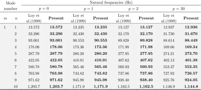
M5) with m =1 and different n, various power law index p are given in Table 3 and are
com-pared with the results of Loy et al. (1999). There is a good agreement between Loy’s and the pre-sent results (only 0.19 % maximum discrepancy with p = 30).
Mode number
Natural frequencies (Hz) 0
p= p=1 p=2 p =30
m n Loy et
al.(1999) Present
Loy et
al.(1999) Present
Loy et
al.(1999) Present
Loy et
al.(1999) Present
1 1 13.572 13.572 13.235 13.235 13.127 13.127 12.937 12.936
2 33.296 33.296 32.430 32.430 32.170 32.170 31.730 31.670
3 93.001 93.001 90.553 90.553 89.828 89.828 88.614 88.449
4 178.06 178.06 173.36 173.36 171.98 171.98 169.66 169.34
5 287.79 287.79 280.20 280.20 277.95 277.95 274.21 273.70
6 422.05 422.05 410.91 410.91 407.62 407.62 402.13 401.38
7 580.78 580.78 565.46 565.46 560.93 560.93 553.37 552.35
8 763.98 763.98 743.82 743.82 737.86 737.86 727.92 726.57
9 971.62 971.62 945.98 945.98 938.40 938.40 925.76 924.05
10 1,203.7 1,203.7 1,171.9 1,171.9 1,162.5 1,162.5 1,146.9 1,144.8
Table 3: Natural frequencies of un-stiffened non-rotating FG cylindrical shell (Hz).
W
(rev/s)
Mode number
Natural frequencies (Hz)
'
b
w '
f w
m n Chen et al.(1993) Present Chen et al.(1993) Present
0.05
1 2 0.00167 0.00167 0.00144 0.00145
3 0.00447 0.00448 0.00430 0.00431
4 0.00847 0.00848 0.00834 0.00835
5 0.01364 0.01366 0.01353 0.01355
0.1
1 2 0.00179 0.00182 0.00135 0.00138
3 0.00456 0.00461 0.00422 0.00427
4 0.00854 0.00859 0.00827 0.00833
5 0.01370 0.01376 0.01348 0.01354
Table 4: Comparison of frequency parameter w' = wR
(
1-n r2)
/E for a very long rotating isotropic cylindrical shell (h/R=0.002, L/R=200, n = 0.3).For the final validation, Table 4 presents the non-dimensional frequency parameter
(
)
' R 1 2 /E
w = w -n r for a very long rotating isotropic cylindrical shells. Results of the present study are compared with those using equation (45) of Chen et al. (1993) for two rotational
0.05
2 2 2 2 4
2
2 2 2 2 2 2
( 1)
2 3
1 1 12 (1 ) ( 1)
b
n n
n Eh n
n n R n
w
r n
- +
= W + + W
+ + - +
2 2 2 2 4
2
2 2 2 2 2 2
( 1)
2 3
1 1 12 (1 ) ( 1)
f
n n
n Eh n
n n R n
w
r n
- +
= W - + W
+ + - +
As indicated in the Table 4, the maximum discrepancy between Chen’s and the present results is 2.4 % at
(
m n,)
=(1, 2). From the above mentioned validation, it can be confirmed that the pre-sent results are in good agreement with those are given by Mustafa and Ali (1989), Loy et al. (1999), and the results using equation (45) of Chen et al. (1993).4.2 Parametric Study
In the next examples, the rotating stiffened functionally graded cylindrical shells are considered (P-FGM Al/ZrO2 model M6 in Table 1). The effects of the power law index, the stiffener’s height-to-width ratio, the circumferential wave numbers, the shell’s length-to-radius ratio, and the shell’s radius-to-thickness ratio on the natural frequencies of functionally graded cylindrical shell areinves-tigated.
4.2.1 Effects of Rotating Speed on the Fundamental Frequency
Table 5 presents the natural fundamental frequencies of the orthogonally stiffened and unstiffened FG cylindrical shells (power law index p=20) with various rotating speed. The variation of the natural fundamental frequencies versus rotating speed is illustrated in Fig. 2.It can be seen that the natural fundamental frequencies for the orthogonally stiffened shell are higher than those for the unstiffened shell. As the rotating speed increases, the fundamental frequency for the unstiffened shell increases more rapidly than that for the stiffened shell. For the stiffened shell, the natural fun-damental frequencies of the backward waves increase with rotating speed while those of the forward waves decrease with rotating speed. In addition, due to the effect of Coriolis force, the backward and forward wave frequencies are different, and the backward wavesfrequencies are always higher than those of forward waves.
Type of shell W (rev/s)
0 10 20 30 50
Stiffened shell wb 344.93 353.24 362.11 371.53 391.96
f
w 344.93 337.16 329.95 323.28 311.55
Unstiffened shell wb 193.84 201.55 212.50 226.46 262.07
f
w 193.84 189.46 188.32 190.19 201.63
Figure 2: Variation of the natural fundamental frequencies of the orthogonal stiffened and unstiffened FG cylindrical shells with the rotating speed (power law index p=20).
4.2.2 Effects of the Stiffener Height-to-Width Ratio on the Fundamental Frequency
The natural fundamental frequency of the orthogonally stiffened FG shells with different stiffener height-to-width ratio
(
h( )r s, /b( )r s,)
and various rotating speeds are listed in Table 6 (stiffener width( ) s r
b is 2 mm). Fig. 3 depicts the effect of stiffener height-to-width ratio on natural fundamental frequency. It is observed that there is an increasing trend of the natural fundamental frequency with increasing height-to-width ratio. The natural fundamental frequency increase more rapidly for small height-to-width ratiothan for large height-to-width ratio. Higher rotating speed causes a big-ger gap between forward and backward wave frequencies.
W (rev/s) Stiffener height-to-width ratios (h/b)
0.5 1 2 3 4 5 7 9
10
W = wb 201.67 204.38 221.37 255.74 305.20 344.63 364.49 394.09
f
w 189.58 192.28 209.24 243.56 292.95 328.58 348.37 377.88
50
W = wb 262.17 264.48 279.06 309.40 354.51 383.46 403.07 432.33
f
w 201.71 203.96 218.39 248.48 293.26 303.20 322.47 351.31
Table 6: Natural fundamental frequencies (Hz) of rotating stiffened FG cylindrical shell with the various stiffener height-to-width ratios.
4.2.3 Effects of the Power Law Index on the Fundamental Frequency
Table 7 shows the fundamental frequencies with different rotating speeds for the various power law indexes of simply supported FG cylindrical shell. The variation the fundamental frequencies with the rotating speed for the various power law indexes is plotted in Fig. 4.
0 5 10 15 20 25 30 35 40 45 50
150 200 250 300 350 400
Rotating Speed (rev/s)
Fun
dam
ent
al
F
reque
nc
y
(H
z)
Figure 3: Variation of the fundamental frequencies for the orthogonal stiffened FG cylindrical shells with the stiffener height-to-width ratio (power law index p =20).
As shown in Fig. 4, the backward and the forward waves increase as power law index p
de-creases. It is basically due to the fact that Young’s modulus of ceramic is higher than metal.
Figure 4: Variation of the fundamental frequencies for the orthogonal stiffened FG cylindrical shells with the rotating speed for the various power law indexes.
0 1 2 3 4 5 6 7 8 9
150 200 250 300 350 400 450
Stiffener Height-to-Width
Fu
nd
am
en
ta
l F
req
uen
cy
(H
z)
Forward Backward =10 =50
0 10 20 30 40 50 60 70 80 90 100
250 300 350 400 450 500
Rotating Speed (rev/s)
Fundam
ent
al
F
req
uenc
y
(H
z)
Power law index W (rev/s)
0 10 20 30 50 60 70 80 100
0
p= wb 369.13 376.11 384.81 395.21 420.86 435.94 448.43 460.07 484.66
f
w 369.13 363.91 360.41 358.52 346.48 341.18 336.34 331.96 324.52
3
p= wb 356.04 364.35 373.18 382.55 402.85 413.76 425.17 437.06 462.22
f
w 356.04 348.27 341.04 334.33 322.48 317.31 312.64 308.45 301.45
20
p = wb 344.93 353.24 362.11 371.53 391.96 402.97 414.48 426.49 451.92
f
w 344.93 337.16 329.95 323.28 311.55 306.47 301.89 297.81 291.05
Table 7: Natural fundamental frequencies (Hz) of stiffened FGM cylindrical shell with the various power law indexes p.
4.2.4 Effects of the Circumferential Wave Number on the Natural Frequency
Figure 5: Variation of natural frequencies for the rotating orthogonally stiffened FG cylindrical shell with the circumferential wave number n (power law index p =20).
W (rev/s) n
1 2 3 4 5 6 7 8
50
W = wb 794.02 405.84 505.37 855.01 1337.79 1935.81 2645.59 3466.04
f
w 697.76 326.60 446.62 810.15 1302.46 1907.38 2622.44 3447.11
100
W = wb 841.22 464.76 583.75 935.80 1417.63 2014.24 2722.61 3541.76
f
w 648.73 306.27 466.19 846.03 1346.92 1957.35 2676.29 3503.88
Table 8: Natural fundamental frequencies (Hz) of stiffened FG cylindrical shell with various the circumferential wave numbers n .
1 2 3 4 5 6 7 8
0 500 1000 1500 2000 2500 3000 3500 4000
Circumferential wave number n
N
at
ur
al
F
req
uenc
y
(H
z)
The natural frequencies for the rotating orthogonally stiffened FG cylindrical shell with various rotating speeds and different circumferential wave numbers n are given in Table 8. The variation
of the natural frequency with the circumferential wave number n is illustrated in Fig. 5. It is seen
that for both rotating speeds, the frequency first decreases to a minimum and then increases with the circumferential wave number n. The backward and forward wave frequencies are almost
identi-cal for the large circumferential wave number n.
4.2.5 Effects of Length-to-Radius Ratio on the Fundamental Frequency
The fundamental frequencies for the rotating orthogonally stiffened FG cylindrical shell with vari-ous length-to-radius ratios L/R are listed in Table 9. Variation of the fundamental frequencies for the rotating orthogonally stiffened FG cylindrical shell versus L/R ratio is plotted in Fig. 6. The natural fundamental backward and forward wave frequencies decrease rapidly with L/R ratio at any rotating speed. The effect of the rotating speed on the fundamental frequency for the small
/
L R ratio is more significant than those for the largeL/R ratio.
Figure 6: Variation of the fundamental frequencies for the rotating orthogonally stiffened FG cylindrical shell with /
L R ratio (power law index p=20).
W (rev/s) L/R
2 4 6 12 16 18 20
10
W = wb 970.641 506.664 284.693 132.437 108.847 95.867 80.265
f
w 959.431 490.879 268.814 116.486 92.880 76.118 60.476
50
W = wb 1001.098 542.781 324.830 182.476 156.150 134.928 119.402
f
w 945.043 463.852 245.427 102.718 57.668 36.185 20.457
Table 9: Natural fundamental frequencies (Hz) of stiffened FG cylindrical shell with various L/R ratios.
2 4 6 8 10 12 14 16 18 20
0 200 400 600 800 1000 1200
Shell Length-to-Radius Ratio (L/R)
Funda
m
ent
al
F
reque
nc
y
(H
z)
4.2.6 Effects of Radius-to-Thickness Ratio on the Fundamental Frequency
Figure 7: Variation of the fundamental frequencies for the rotating orthogonally stiffened FG cylindrical shell with R/h ratio (power law indexp =20).
Table 10 gives the natural fundamental frequencies for the orthogonally stiffened FG cylindrical shell with various R/h ratios and rotating speeds. Fig. 7 depicts the variation of natural funda-mental frequencies with respect to radius-to-thickness ratioR/h. It can be seen that the natural fundamental backward and forward wave frequencies for the orthogonally stiffened rotating cylin-drical shell decrease as the R/h ratio increases. The effect of rotating speed for the large R/h ratio is also more significant than those for the small R/h ratio.
W (rev/s) R/h
100 150 200 300 400 450 500
10
W = wb 672.235 351.174 239.728 125.005 87.800 78.195 71.402
f
w 660.673 339.344 227.794 115.608 78.358 68.741 61.938
50
W = wb 706.956 396.529 294.480 221.795 195.024 187.476 181.949
f
w 649.141 337.363 234.782 161.659 134.684 127.061 121.468
Table 10: Natural fundamental frequencies (Hz) of stiffened FG cylindrical shell with various R/h ratios.
5 CONCLUSIONS
Based on the Love’s first approximation theory and the smeared stiffeners technique, the analytical solution for the vibrations of the orthogonally stiffened rotating functional graded material cylindri-cal shell has been presented. The natural frequencies are compared with the existing published
re-100 150 200 250 300 350 400 450 500
0 100 200 300 400 500 600 700 800
Shell Radius-to-Height Ratio (R/h)
Fu
nda
m
ent
al
F
requ
enc
y
(H
z)
sults for the non-rotating orthogonally stiffened isotropic cylindrical shell, the non-rotating unstiff-ened FG cylindrical shells, and the rotating isotropic cylindrical shell. The following points can be outlined from the present study:
The natural fundamental frequency of FG cylindrical shell can beincreased by stiffening with orthogonal stiffeners. The natural fundamental frequencies for the backward and the forward waves increase with the rotating speed, the gap between the backward and the forward waves is greater with higher rotating speed. The backward wave frequencies are higher than the forward frequencies due to the effect of Coriolis force.
The natural fundamental backward and forward wave frequencies for the orthogonally stiffened rotating cylindrical shell decrease with increasing L/R
(
R/h)
ratio. The effect of rotating speed with the large L/R(
R/h)
ratio is greater than the effect of those with small L/R(
R/h)
ratio.Acknowledgements
This research is funded by Vietnam National Foundation for Science and Technology Development (NAFOSTED) under grant number: 107.02-2015.14.
References
Bich, Dao Huy, Dao Van Dung, and Vu Hoai Nam(2012).Nonlinear Dynamical Analysis of Eccentrically Stiffened Functionally Graded Cylindrical Panels. Composite Structures 94.8: 2465-2473.
Chen, Y., Zhao, H. B., Shea, Z. P. (1993). Vibrations of High Speed Rotating Shells With Calculations for Cylindri-cal Shells. Journal of Sound and Vibration 160: 137-160.
Lam, K.Y., and Loy,C.T. (1994). On Vibrations of Thin Rotating Laminated Composite Cylindrical Shells. Compo-sites Engineering 4.11: 1153-1167.
Lam, K.Y., and Loy,C.T. (1995). Analysis of Rotating Laminated Cylindrical Shells by Different Thin Shell Theo-ries. Journal of Sound and Vibration 186.1: 23-35.
Lam, K.Y., and Wu Qian (1999). Vibrations of thick rotating laminated composite cylindrical shells. Journal of Sound and Vibration 225.3: 483-501.
Lee, Young-Shin, and Young-Wann Kim(1998). Vibration Analysis of Rotating Composite Cylindrical Shells with Orthogonal Stiffeners. Computers & Structures 69.2: 271-281.
Li, S. R., Fu, X. H., Batra, R. C. (2010). Free vibration of three-layer circular cylindrical shells with functionally graded middle layer. Mechanics Research Comunications, 37(3), 577-580.
Loy, C.T., Lam,K.Y., and Reddy,J.N. (1999).Vibration of Functionally Graded Cylindrical Shells. International Journal of Mechanical Sciences 41.3: 309-324.
Mustafa, B.A.J., and Ali,R. (1989). An Energy Method for Free Vibration Analysis of Stiffened Circular Cylindrical Shells. Computers & Structures 32.2: 355-363.
Pradhan, S.C. et al(2000). Vibration Characteristics of Functionally Graded Cylindrical Shells under Various Boundary Conditions. Applied Acoustics 61.1: 111-129.
Sun Shupeng, Shiming Chu, and Dengqing Cao(2012).'Vibration Characteristics of Thin Rotating Cylindrical Shells With Various Boundary Conditions. Journal of Sound and Vibration 331.18: 4170-4186.
Xiang, Song et al(2012). Natural Frequencies of Rotating Functionally Graded Cylindrical Shells. Applied Mathe-matics and Mechanics 33.3: 345-356.
Zhao, X., Liew, K.M., and Ng,T.Y. (2002). Vibrations of Rotating Cross-Ply Laminated Circular Cylindrical Shells with Stringer and Ring Stiffeners. International Journal of Solids and Structures 39.2: 529-545.
APPENDIX
The differential operators Lijin equation (7):
'
2 2 2
' 66 2
11 11 2 2 2 2
' ' ' ' 2
12 66 12 66
12 2 2
' 3 ' ' 3
2 '
12 12 66
13 11 3 2 2 2
2
t t
t A
L A
x R t
A A B B
L
R R R R x
A B B
L R B
R x x R R x
r r q q r q æ ö
¶ çç ÷÷ ¶ 
= +ç + W ÷÷
-ç ÷
¶ è ø¶ 
æ ö ¶÷
ç ÷
ç
=çç + + + ÷÷ ÷ ¶ 
è ø
æ ö÷ ¶ ¶ æ ö÷ 
ç ÷ ç ÷
ç ç
=çç - W ÷÷÷¶ - -çç + ÷÷÷
¶ ¶ 
è ø è ø
' ' ' ' 2
2
12 66 12 66
21 2 2
' ' 2 ' ' ' 2 2
' 66 66 22 22 22 2
22 66 2 2 2 3 4 2 2
' ' ' ' '
22 22 12 66 12
23 2 3 2
2 2
2 t
t t
A A B B
L R
R R R R x
B D A B D
L A
R R x R R R t
A B B B D
L
R R
R R R
r
q
r r
q
q
æ ö ¶÷
ç ÷
ç
=çç + + + + W ÷÷
÷ ¶ 
è ø
æ ö÷ ¶ æ ö÷ ¶ 
ç ÷ ç ÷
ç ç
=ç + + ÷÷ +ç + + ÷÷ - + W
ç ÷¶ ç ÷¶ 
è ø è ø
æ ö ¶÷
ç ÷
ç
=çç + ÷÷ - + +
÷ 
è ø
' 3 ' ' 3
66 22 22
2 2 3 4 3
2
2 t
D B D
t
R x q R R q r
æ ö÷ ¶ æ ö÷ ¶ 
ç ÷ ç ÷
ç + ÷ -ç + ÷ - W
ç ÷ ç ÷
ç ÷¶ ¶ ç ÷¶ 
è ø è ø
' ' '
3 3
' 12 66 12
31 11 3 2 2 2
' ' ' ' 3 ' ' 3 ' '
2
12 66 12 66 22 22 22 22
32 2 2 2 3 4 3 2 3
' 2 12 33 2 2 2 2 2 2 t t
B B A
L B
R x
x R R x
B B D D B D A B
L
R R R R x R R R R t
B L D R x q r r q q q æ ö
¶ çç ÷÷ ¶ 
= +ç + ÷÷
-ç ÷ 
¶ è ø¶ 
æ ö÷ ¶ æ ö÷ ¶ æ ö÷ ¶ 
ç ÷ ç ÷ ç ÷
ç ç ç
=ç + + + ÷÷ +ç + ÷÷ -ç + + W ÷÷ + W
ç ÷¶ ¶ ç ÷¶ ç ÷¶ 
è ø è ø è ø
=
-
' '
4 4
' 12 66
11 4 2 2 2 2
' 2 ' 4 ' 2
2 2
22 22 22
3 2 4 4 2 2
2 4
2
t t t
D D
x R R x
B D A
R R R t
q
r r r
q q
æ ö
¶ -çç + ÷÷÷ ¶ +
ç ÷
ç ÷
¶ è ø¶ 
æ ö÷ ¶ ¶ æ ö÷ 
ç ÷ ç ÷
ç + W ÷ - +ç W - ÷
-ç ÷ ç ÷
ç ÷¶ ¶ ç ÷ 
è ø è ø
The coefficients kijin equation (10):
2 2 2 2 2 2 2 ' 2 2 ' 2 2 2
66 11
11 2 2
(J Lt R n J L Rt A L n A R m )
k
L R
w p
- W - + +
=
' ' ' '
12 66 12 66
12 2
( )
mn B B A R A R
k
LR
p + + +
' 2 2 ' 2 2 ' 2 ' 2 2 2 2 2 3
12 66 12 11
13 3 2
( 2 t )
m B L n B L n A L R B R m J L R
k
L R
p + + + p - W
=
' ' ' ' 2 3
12 66 12 66
21 2
( t )
mn B B A R A R J R
k
LR
p + + + + W
=
' 2 4 2 ' 2 3 2 ' 2 2 2 ' 2 2
66 66 22 22
22 2 4
2 2 4 2 4 2 ' 2 2 ' 2 2 2
22 66
2 4
( 2 2 )
( t t )
A R m B R m A L R n B L Rn
k
L R
J L R J L R D L n D R m
L R
p p
w p
+ + +
+ +
=
-- W
-' 2 ' 2 2 ' 2 3 ' 2 3 2 ' 2 3 2
22 22 22 12 66
23 2 4
' 2 3 ' 2 2 2 ' 2 2 2 2 4
22 12 66
2 4
( 2 )
( 2 2 t )
B L Rn A L R n B L Rn B R m n B R m n
k
L R
D L n D R m n D R m n J L R
L R
p p
p p w
+ + + +
=
-+ + - W
-' 2 2 ' 2 2 ' 2 ' 2 2 2
12 66 12 11
31 3 2
( 2 )
m B L n B L n A L R B R m
k
L R
p + + + p
=
' 2 ' 2 2 ' 2 3 ' 2 3 2 ' 2 3 2
22 22 22 12 66
32 2 4
' 2 3 ' 2 2 2 ' 2 2 2 2 4 2 2 4
22 12 66
2 4
( 2
( 2 2
)
)
t t
B L Rn A L R n B L Rn B R m n B R m n
k
L R
D L n D R m n D R m n J L R J L R n
L R
p p
p p w
+ + + +
= -
-+ + - W + W
' 4 2 ' 4 2 4 2 4 ' 2 2 3 2
22 22 12
33 4 4
4 2 4 2 4 4 2 ' 4 4 4 ' 4 4 ' 2 2 2 2 2 ' 2 2 2 2 2
11 22 12 66
4 4
( 2 2
( 2 )
)
4 t
t t
A L R B L Rn J L R B L R m
k
L R
J L R n J L R D R m D L n D L R m n D L R m n
L R p
w p p p
+ - W +
= -