Aditya Kulkarni Int. Journal of Engineering Research and Applications
www.ijera.com
ISSN : 2248-9622, Vol. 4, Issue 11(Version - 5), November 2014, pp.113-116
www.ijera.com 113 | P a g e
Implementation and Performance Analysis of Kaiser and
Hamming Window Techniques on FPGA
Aditya Kulkarni*, Dr. Ravi Sindal**
*(Research Scholar, IET DAVV Indore M.P,)
** (Professor, Department of E&TC, IET DAVV Indore M.P)
Abstract:
Considering the importance of real time filtering, a comparison was done between two prominent window techniques known for digital filtering. A 16 tap digital band pass FIR filter is designed for each design technique (Kaiser and Hamming) and implemented over FPGA. The Simulink model of the filter confirms the correctness and other properties of the digital filter. Further a hardware descriptive code (VHDL) is generated for the designed filter which then will be loaded on to the FPGA. The VHDL code is speed optimized. The VHDL code is simulated and synthesized in Xilinx ISE. Further the performance analysis is done on FPGA to determine the applicability of the filter.
Keywords:
FIR, FPGA, Hamming, Kaiser, VHDL,I.
Introduction
Real time processing of signals has become a great challenge today in the field of Digital Signal Processing (DSP). Increasing data rates, complex coding, and limited bandwidth challenge the designers today. Finite Impulse response filter (FIR) remains the first choice for reliable signal extraction. Linear phase desirability is the key to minimize the noise incorporated into the signal while filtering. FIR having constructional linear phase response, is affordable than its counterpart Infinite Impulse response (IIR) filter. Window Technique is the prime choice of design due to ease in implementation on digital platforms like FPGA.
The other design styles as the Equiripple method is not preferred as designing a digital circuit for such methods are difficult. There are various digital filtering algorithms which are used for various general purpose applications. Hence each application has its specific specification and limitations. This paper helps understand the parameters necessary to select a particular algorithm for a designing a FIR filter for its specific application. The aim of the paper was to realize the filter structure on a FPGA so that the design can be realized as an ASIC comparing two filter structures recognizes the area of applications.
II.
Filter designing
A Digital filter can be best modeled as a Linear constant coefficient difference equation as described by equation (1)
� − � = =0 � [ − ]
N
k=0 (1)
As there is no feedback involved in the FIR filter the generalized Digital filter equation can be reduced to the form represented by equation (2)
y[n] = =0 � [ − ] (2)
The parameter M denotes the length of any filter which is called as Filter tap. The response of any filter greatly depends upon its length. There is a linear relationship between the cutoff of the filter and its length. As we go on increasing the length of the filter we tend to get a sharper cutoff characteristic.
But it is a great disadvantage in the case of implementation as for greater filter lengths we need
FPGA’s with larger storage capacity. There is one
more important parameter to be studied which is bk which is called Filter coefficient. Kaiser window filter was the first filter to be analyzed. It is described as in equation (3)
ω n = �0(� 1−(1− 2
−1))
�0(�) (3)
Where I0(.) denotes the presence of Bessel function with Zero order. The Bessel expansion depends on the shape parameter�, which further depends on the length of the filter denoted by parameter M. The shaping parameter allows adjusting the main lobe width and side lobe attenuation. Selecting a proper value of M can produce variety of transition band and optimal stop band attenuation. The parameter design criterion as shown
Aditya Kulkarni Int. Journal of Engineering Research and Applications
www.ijera.com
ISSN : 2248-9622, Vol. 4, Issue 11(Version - 5), November 2014, pp.113-116
www.ijera.com 114 | P a g e �=
0 � ≤21
0.5842 � −21 0.4 + 0.07886 � −21
21≤ � ≤50 0.1102 � −8.7 � > 50
The Hamming window technique is more convenient than the earlier counterpart as it relies on its design equation. The window was designed to minimize the nearest side lobe. A Hamming window is denoted by equation (4)
ωH(n)= 0.54−0.46 cos
2�
−1
0 ℎ� � �
0≤ ≤ −1 (4)
Two filters were designed using both the methods for lower and upper cutoff frequencies to be 10 and 30 kHz respectively, with sampling frequency of 140 kHz.
The modeling was carried out in Simulink with additional noise simulation to replicate a real world scenario.
III.
Filter Coefficient Calculation and
Implementation of HDL
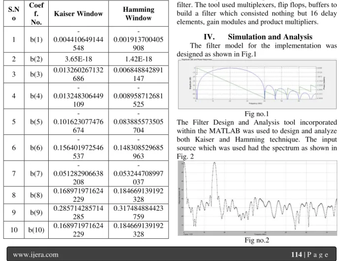
The coefficients were calculated in Simulink during the modeling of the filter. The standard equation was followed in this process. For a 16tap filter the coefficients for both filters are shown below.
Table no.1 Coefficients of a 16 tap filter
S.N o
Coef f. No.
Kaiser Window Hamming Window
1 b(1)
-0.004410649144 548 -0.001913700405 908 2 b(2) 3.65E-18 1.42E-18
3 b(3) 0.013260267132 686
0.006848842891 147
4 b(4)
-0.013248306449 109 -0.008958712681 525
5 b(5)
-0.101623077476 674 -0.083885573505 704
6 b(6)
-0.156401972546 537 -0.148308529685 963
7 b(7)
-0.051282906638 208 -0.053244708997 037
8 b(8) 0.168971971624 229
0.184669139192 328
9 b(9) 0.285714285714 285
0.317484884423 759
10 b(10) 0.168971971624 229
0.184669139192 328
11 b(11)
-0.051282906638 208 -0.053244708997 037
12 b(12)
-0.156401972546 537 -0.148308529685 963
13 b(13)
-0.101623077476 674 -0.083885573505 704
14 b(14)
-0.013248306449 109 -0.008958712681 525
15 b(15) 0.013260267132 686
0.006848842891 147 16 b(16) 3.65E-18 1.42E-18
17 b(17) -0.004410649
-0.001913700405
908
As the FIR filter is a linear phase filter we can confirm it by observing the coefficient values. The values obtained by the Simulink simulation confirm the symmetric design of the filter. These filters are designed for implementation on xc3s400-5fg320 XILINX FPGA. The coefficients were converted into fixed point format. This conversion enabled the filter HDL to be recognized by the software.
The synthesis tool (Xilinx ISE) uses the HDL code to realize a digital circuit representing the modeled filter. The tool used multiplexers, flip flops, buffers to build a filter which consisted nothing but 16 delay elements, gain modules and product multipliers.
IV.
Simulation and Analysis
The filter model for the implementation was designed as shown in Fig.1
Fig no.1
The Filter Design and Analysis tool incorporated within the MATLAB was used to design and analyze both Kaiser and Hamming technique. The input source which was used had the spectrum as shown in Fig. 2
Aditya Kulkarni Int. Journal of Engineering Research and Applications
www.ijera.com
ISSN : 2248-9622, Vol. 4, Issue 11(Version - 5), November 2014, pp.113-116
www.ijera.com 115 | P a g e
The signal source along with the noise had a bandwidth of over 70 kHz. The noise was added to simulate the real life conditions. The output of the filter denotes the major component of the signal present for the given 20 kHz bandwidth. The response of the Kaiser filter was as shown in fig.3
Fig no.3
The response of the Hamming window indicated the prominent presence of first side lobe when compared to the response of Kaiser. The Hamming filter’s output spectrum is shown in fig. 4
Fig no.4
The Simulink design by default possessed floating point number format for the coefficients. For implementation over the Xilinx FPGA the format had to change from floating to fixed point system. Fixed point designer bundled within the Simulink was used to obtain the desired result. The fixed point format was set to 8 bit signed format to support a range of applications. While synthesis it was observed that there was a significant change in the resources consumed over the FPGA.
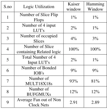
Kaiser window used more digital components than its filter counterpart. A comparative table (table no.2) which was generated by observing the results from the synthesis tool shows the difference in device utilization.
Table no.2 Device utilization comparison
V.
Conclusion
Digital filters have a very dynamic and extensive range of applications in present digital world. In this paper the comparison done between the two filters which were designed and simulated in SIMULINK and XILINX on when they are implemented on a FPGA xc3s400-5fg320 device. The aim was to classify the implementation of the filter on the basis of the chip area, efficiency and accuracy. The results of the comparison established a clear understanding of the application of these filters. Kaiser being superior in terms of the frequency characteristics, Hamming on the other hand could be preferred for an application with a low chip size area. Further the designing could be implemented for the floating point format for comparison. Floating point format can increase the accuracy of the filter further.
References
[1]. http://en.wikipedia.org/wiki/Floating_point
[2]. http://cp.literature.agilent.com/litweb/
pdf/systemvue2006/ FPGA%20Xilinx.pdf
[3]. Perry D., .VHDL., 3rd Edition, Tata Mc. Graw Hill Publications, 2001.
[4]. Bhaskar J., VHDL primer. , 3rd Edition, Pearson Education Asia Publications, 2000. [5]. Prokis J.G.,Manolakis D.G.,Digital Signal
Processing., 3rd Edition, PHI publication 2004.
[6]. Mitra S. K, .Digital Signal Processing. 3rd Edition,Tata Mc. Graw Hill Publications. [7]. Burrus C S, .Digital Filters Structures
described by Distributed Arithmetic.,IEEE Transactions on Circuits and Systems, vol. CAS-24, page: 12, December 1977.
S.no Logic Utilization Kaiser window
Hamming Window
1 Number of Slice Flip
Flops 1% 1%
2 Number of 4 input
LUT's 2% 1%
3 Number of occupied
Slices 4% 3%
4 Number of Slice
containing Related logic 100% 100%
5 Total Number of 4
Input LUT's 2% 1%
6 Number of Bonded
IOB's 9% 9%
7 Number of
MULT18X18s 93% 81%
8 Number of
BUFGMUXs 12% 12%
9 Average Fan out of Non
Aditya Kulkarni Int. Journal of Engineering Research and Applications
www.ijera.com
ISSN : 2248-9622, Vol. 4, Issue 11(Version - 5), November 2014, pp.113-116
www.ijera.com 116 | P a g e
[8]. Lee H.,Sobelman G E. .Performance Evaluation and Optimal design for FPGA based Digit-serial DSP Functions Computers and Electrical Engineering 2003
[9]. Mirzaei S., Hosangadi A. and Kastner R.,FPGA Implementation of High Speed FIR Filters Using Add and Shift Method., International Conference on Computer Design (lCCD ),pp 30S-313, 2006.
[10]. Zhang Chi and Guo Li Li, Design of FIR filter with Matlab and running on FPGA, Applied Science and Technology. vol. 33, no. 6, pp.83, Jun. 2006
[11]. Mumun Bin Ibne Reaz,Mohammad Turiqul Islam, MOM. Shuhiman Suluimun,Mold. Alauddiii MOM. Ali, Husun SurwaJ and Shahidu Rufiqud FPGA Realization Of Multipurpose FIR Filter
[12]. Mamun Bin Ibne Reaz, Md Shahidul Islam, Md Shahiman Sulaiman, Md. Alauddin Ali, A Multipurpose FIR Filter Design Using VHDL, Proceedings of The Int. Con/: on Robotics, Vision, In/: And Signal Processing, Malyasia, pp422-427.
[13]. Evans, J.B., An Efficient FIR filter Architecture, Proceedings of IEEE
Symposiurn on Circuits and Systems, pp627-630, 1993.
[14]. Zhou Ya feng , Li Yue Hua and Zhu Hao,
Design of 16 order FIR filter based on FPGA. Journal of Nanjing University of Technology, vol. 27, no.1, pp.46, 2005.