The Fir Digital Filter Design based on Iwpso
Xinnan Hu
1College of Electronic and Electrical Engineering Shanghai University of Engineering Science Songjiang
District, Shanghai 201620, China
Yujia Wang
2College of Electronic and Electrical Engineering Shanghai University of Engineering Science Songjiang
District, Shanghai 201620, China
Kun Su
3College of Electronic and Electrical Engineering
Shanghai University of Engineering Science Songjiang District, Shanghai 201620, China
Abstract—The essence of finite impulse response (FIR) digital filter design is the problem of the parameter optimization. Namely the optimal parameters of FIR digital filter are the core of the design. In due to the traditional design method of FIR digital filter is not only accuracy not high but also sideband frequency is difficult to determine. Improve Weight Particle Swarm Optimization (IWPSO) to design FIR digital filter has less calculation and fast convergence speed. The simulation results also demonstrate that the IWPSO has better appro-ximation properties and band-pass characteristics. what’s more, the convergence of IWPSO algorithm made good results in filter design efficiency.
Keywords—FIR filter design; parameter optimization; improve weight particle swarm optimization
I. INTRODUCTION
FIR digital filter can change its amplitude frequency randomly and can guarantee accurate linear phase at the same time, accordingly it has bright research prospect. FIR digital filter is a basic computing unit of digital signal processing[1]and plays an important role in communication field and in the processing of digital signal. The design core of the FIR digital filter[2]centers on the optimization of multidimensional variable[3]. The design method of FIR digital filters are mainly: window function method, Chebyshev and frequency sampling method etc. However, the window function method cannot properly handle transition band. The Frequency Sampling Method results in the fluctuation on the edge of passband and the sampling frequency is restricted to integral number of 2π/ Nwhich cannot be sure the value of the cut-off frequency.
N
should be taken into consideration if need choose any value of the cut-off frequency, but this increases the amount of calculation. The newly emerged methods such as Genetic Algorithm(GA)[4], neural network method[5] and Particle Swarm Optimization(PSO) algorithm[6], although those methods do have its inspiring effects but still have serious shortcomings such as high complexity and slow convergence rate etc.For the defects of traditional FIR digital filter, this paper will introduce particle swarm algorithm into the design of FIR digital filter. Then, it will elaborate the process of the FIR digital filter design of using IWPSO. Finally, it draws the conclusion that IWPSO method has better approximation properties, algorithm convergence and optimal value by compare with traditional method and standard PSO algorithm.
The rest of the paper is arranged as follows. In section II, the FIR filter design problem is formulated. In section III briefly discusses on conventional PSO employed for the FIR filter design problems and the proposed IWPSO algorithm. Section IV describes the simulation results obtained by Hamming windows, Frequence sample, PSO and IPSO. Finally, Section V concludes the paper.
II. THE OPTIMAL DESIGN OF FIR DIGITAL FILTER A FIR digital filter which can be described by difference equation,
N -1
k=0
y(n)=
h(k)x(n - k)
Where N is the order of the filter. h k
is the filter’s impulse response. The values ofh k
will determine the type of the digital filter i.e. LP, HP, BP, BS etc. FIR digital filter has serious linear sequence property[7], so the unit impulse response has to be odd-symmetry and even-symmetry, namely,y(n)= y(N - 1- k)
Hypothesish(0),h(1),
,h(N - 1)
is unit sampling responses of N in FIR digital filter. By Z transform[8] of , it can draw the transmission function as below,N -1 -n
k=0
If
z = e
jω, it can draws the frequency response function as follow,
jω N -1
jωn n=0H e
=
h n e
Digital filter can be expressed as,
jω jω j (ω) jθ(ω)
H(e )= H(e ) e = H(ω)e
The designed digital filter has linear phase, requiring
θ
(
ω
)
isω
linear function, namely,θ
(
ω
)= -
ω
, including is a constant.According to the requirements of design a filter and the
amplitude function
jw i
H (e )
, suppose the designed amplitude
function as
jw d
H (e )
, so the weighted error[9-10] can be represented as follow,
jωi jωi
i d
E(ω)= W(ω) H (e ) - H (e )
Thus:
jωi N -1
jωn in=0
E ω = W(ω) H (e ) -
h n e
In the above,
W(
ω
)
is the weighting function used toprovide different weights for the approximate errors in different frequency bands,
W(
ω
)
should be maximum in thehigh precision frequency band.
W(
ω
)
should be minimum inthe low precision frequency band. The designing of FIR filter can be supposed as,
p p s
s
1
,0
ω ω
,k =
δ
/
δ
k
W(
ω
)=
0,
ω
ω π
In the above,
p
is pass band ripple peak ands
is stop band ripple peak. The error fitness function given in (9) has been considered as fitness function in many literatures [11].The error to be minimized is defined as:
p s
p s
ω ω ω ω
F = max E
ω
-
+ max E
ω
-
Obviously, the coefficient of the filter gets better along with F becoming smaller. (9) represents the error fitness function to be minimize using IWPSO algorithms. The algorithms try to minimize this error. The core part of designing FIR digital filter is to find the optimal filter coefficient. In order to use IWPSO algorithm to solveh k
, itIII. THE OPTIMAL DESIGN OF FIR DIGITAL FILTER BASED ON IWPSO
A. The Basic Particle Swarm Optimization (PSO) Algorithm
Particle swarm based on the swarm intelligence theory is an optimal algorithm developed by Eberhart[12]. The particle traces the two extremes which local optimum and global optimum in each process of iterative search. Then it adjusts its position and velocity to achieve the goal of optimum.
The position and velocity formula of the particle swarm is given as,
1
k+1 k k k k k
id id 1 i id 2 2 i id
k+1 k k+1
id id id
v
=
ω
v + c r pbest - x
+ c r (gbest - x )
x
= x + v
In the formula ,
i k
x
is d dimensional velocity of ith in
the kth iteration.
k id
x
is d dimensional position of ith in the kth iteration.
ω
is the inertia weight coefficient which keeps theparticle inertia and enable it can discover the new areas.
c
1and2
c
are acceleration constants which push every particle
accelerates to pBest and gBbest. r1 与 r2 are the random number between 0 and 1.
B. The Illustration of IWPSO
The paper [13] revised the above formula by introducing inertia weight factor. Then Van den Bergh and Engelbrech[14] pointed out,
1
1 21
2
ω
> (c + c ) -
Assure the particle's convergence. If the condition cannot be satisfied, it may lead to diverging or periodic actions. Contemporarily, researchers often adopt the linear decreasing weight proposed by Ismail A[15].
max max min
max
G
ω
=
ω
-
ω
-
ω
*
G
max G
is the maximum evolution algebra.
ω
max is themaximum inertia weight.
ω
minis the minimum inertia weight.Where ωmax=0.9 ,
ω
min=
0.4
.With linear inertia weightdecreasing small, A particle swarm optimization algorithm with the Strategy of Nonlinear decreasing inertia weight will converge significantly. The (12) can be improved as following,
2
2max max min
max max
* G
G
ω
=
ω
-
ω
-
ω
*
Step2 The initial positions and velocities of all particles are generated randomly within the n-dimensional search space. Initialize pBest and gBest of population size.
Step3 Evaluate the fitness values of particles and store the position of particle having best fitness value as gBest.
Step4 Every particle follows the position update formula and velocity update formula (10) to adjust its velocity and position.
Step5 Evaluate the fitness values of updated particles,
For newly generated particlei i = 1,2,
,M
, if Fitness(i) better than fitness(pBest), pBest=i. If fitness(i) better than Fitness(gBest), gBest=i.Step6 If the iterations achieve to the Maximum number of iterations, the algorithm terminates, Fitness(gBest) is good enough, The gBest is Solution. Otherwise, go to setp2 for a new round of iteration.
IV. SIMULATION AND ANALYSIS
In order to compare the optimal algorithms in terms of the error fitness with traditional design method, it will draws the advantages of the improved one and prove the validity of the IWPSO algorithm. By comparing, it can counts the ideal unit impulse response of the low pass filter as following,
jω d1,0
ω
0.3
π
H
e
=
0,0.4
π ω π
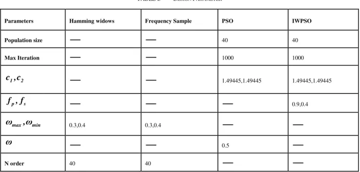
(14)TABLE.1. shows the design parameter of all kinds digital filter design methods. In order to demonstrate the effectiveness of the proposed filter design method, several examples of FIR digital filter are constructed using Hamming widows, Frequency Sample, PSO and IWPSO. The MATLAB[16-17] simulation has been performed extensively to realize the FIR LP digital filter of the order 40.
When it comes to the improvement of weight’s linear
characteristic, it is easy to find that with the increase of iteration, the improved weight decreases rapidly. All these can prove that it can improve significantly the convergence of the algorithm.
Fig.2 shows the design characteristics of all kinds of filter design methods. By the following comparison from Fig.2 we can conclude the buffer zone of the window function decreases smoothly. But if the buffer zone is too wide, the decrease become slow. However, the Frequency Sampling Method leads to the dramatically fluctuating on the edge of pass-band which may influence the pass-band characteristic. When it compares with the traditional method, the improved method has the better pass-band and stop-band, so the inner side of the pass-band is smooth enough to help the signal pass
without distortion. What’s more, the improved method has a
more narrow transition bandwidth, which should be solved quickly in the signal communication system.
IWPSO is an optimal method, by simulation, which can draw the following unit impulse response coefficient of IWPSO and PSO in TABLE 2.
TABLE I. DESIGN PARAMETER
Parameters Hamming widows Frequency Sample PSO IWPSO
Population size 40 40
Max Iteration 1000 1000
1 2
c ,c
1.49445,1.49445 1.49445,1.49445p s
f , f
0.9,0.4max min
ω
,
ω
0.3,0.4 0.3,0.4ω
0.5Fig. 1. The comparison of the two linear weight decrease curves Fig. 2. The simulation result of different methods
TABLE II. OPTIMAL RESULT OF THE 40ORDER UNIT IMPULSE RESPONSE
h(N) PSO IWPSO h(N) PSO IWPSO
h(0)=h(20) 1.01202819879665 1. 01993808983423 h(10)= h(30) -0. 0124072369246805 0. 00978281196760191
h(1)=h(21) 0.998060873960858 0. 984640179011981 h(11)= h(31) -0. 00979470870422273 -0. 00196404276610325
h(2)= h(22) 0. 991541707693223 1. 00380591019032 h(12)= h(32) 2. 59553011699883e-05 -0. 0197163205167412
h(3)= h(23) 1. 01092716101786 1. 02127652877248 h(13)= h(33) 0 .00598039898460515 0. 00358347947328555
h(4) = h(24) 0 .986452700263352 0. 979822946574317 h(14)= h(34) 0. 0136135775471002 0. 00219139922982807
h(5) = h(25) 0. 985670120151296 0. 980068510678159 h(15)= h(35) 0. 000925728610695822 -0. 0208888321837131
h(6) = h(26) 0. 0149680758504600 0. 0181362870809082 h(16)= h(36) -0. 00943301422868145 0. 00151877405571810
h(7) = h(27) 0. 00365264987363669 0. 0211191618692504 h(17)= h(37) -0. 00960102613115888 0. 00989747977171325
h(8) = h(28) 0. 00586418920727231 -0. 0117393209595076 h(18)= h(38) 0. 0125120671876658 0. 0113361221972772
h(9) = h(29) -0. 00963133762554668 0. 00978281196760191 h(19)= h(39) -0. 00984607345164511 -0. 0150980644781148
0
200
400
600
800
1000
0.4
0.5
0.6
0.7
0.8
0.9
Iteration times
In
e
rt
ia
We
ig
h
ts
Linear Descend
Non-Linear Descend
0 0.2 0.4 0.6 0.8 1
-0.2 0 0.2 0.4 0.6 0.8 1 1.2
Frequency凚 w/pi凛
M
a
g
n
it
u
d
e
PSO
IWPSO
Hamming Window
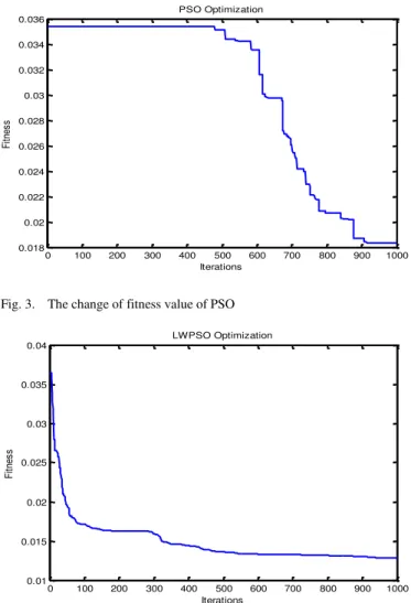
The Fig.3 and Fig.4 are coefficients optimal process of PSO and IWPSO respectively:
Fig. 3. The change of fitness value of PSO
Fig. 4. The change of fitness value of IWPSO
After 1000 iterations, the TABLE.3 shows the simulation results of PSO and IWPSO. Both methods can achieve a good low-band effect. However, at the same coefficient design, IWPSO can get optimal result but use less time and smaller fitness function compared with PSO, which also can get a better optimal coefficient as TABLE. 3.
TABLE III. THE COMPARISON OF SIMULATION RESULTS BETWEEN PSO
AND IWPSO
Optimization algorithm PSO IWPSO
Optimization of time 16.926600s 16.745021s
Minimum Fitness 2.372231e-02 2.076231e-02
V. CONCLUSION
To make up the deficiencies of traditional design of filter, the paper introduces IWPSO to improve the design method. To prove the validity of IWPSO method, the thesis compares to traditional method, PSO method, and the improved method. The major findings of the thesis are the IWPSO method has better convergence speed, better optimal coefficient, and approximation of the ideal filter. Therefore, the algorithm method has a brilliant application prospect in the field of signal process. Further analyze and improve the weights of PSO algorithm is primary aim in the future. what’s more, the improved optimization algorithms applied to the moving average FIR filter, the dressing filter, the L-wave band filter and other modern filter are future research direction.
REFERRENCE
[1] Rao, P. Signals and Systems. McGraw-Hill,2008
[2] Ababneh,J.I.,Batanineh,M.H., Linear phase FIR filter design using partical swarm optimization and genetic algorithms.Digital Signal Process.2008.
[3] J. Branke, H. Schmeck, K. Deb, and R. S. Reddy, ―Parallelizing
multiobjective evolutionary algorithms: Cone separation,‖ in Proc. Congr. Evol.Comput., Portland, OR, 2004, pp. 1952–1957.
[4] H. J. C. Barbosa and A. M. S. Barreto, ―An interactive genetic algorithm with co-evolution of weights for multiobjective problems,‖ in Proc. 2001 Genetic Evol. Comput. Congr., 2001.
[5] J. Kennedy, Eberhart R. Paticle Swarm Optimization[C]. Proceedings of IEEE International Conference on Neural Networks.1995.
[6] Y. Shi and R. C. Eberhart,―Fuzzy adaptive particle swarm
optimization,‖in Proc. IEEE Congr. Evol. Comput.[A]. vol. 1. May 2001.
[7] Oppenheim,A.,andSchafer,R.Discrete-Time Signal Processing,3rd edition.Prentice Hall,2011.
[8] Yanfen Wang, Gang Wang, Xiaoguang Zhang. Digital signal processing and implementation[M]. Tsinghua University press.
[9] Li K, Liu Y. ―The FIR windows function design based on evolutionary
algorithm‖ [C]. International conference on Mechatronic Science,
Electric Engineering and computer (MEC),IEEE.2011.
[10] KONAKAHARA T, SUYAMA K. Design of CSD Coefficients FIR Filters using PSO with Perturbation[J]. Technical Report of Ieice Cst, 2010, 110.
[11] Ababneh,J.I., Bataineh, M.H.,Linear phase FIR filter design using particle swarm optimization and genetic algorithms.Digital Signal process.2008
[12] Eberhart,R.,Shi,Y.,Comparison between genetic algorithms and particle swarm optimization.In: Proc.7th Ann.Conf.Evolutionary Computation,San Diefo.2000
[13] Shi Y, Eberhart R.C., Empirical study of particle swarm optimization[C]//Proc.IEEE Congr.Comput.Intell.1998.
[14] Van den Bergh F,Engelbrecht A P.A study of Particle swarm optimization particle trajectories[J].Information sciences,2006. [15] Ismail A, Engelbrecht A, The Self-adptive Comprehensive Learning
Particle swarm Opyimizer[J]. Swarm Intelligence(Lecture Note in Computer Science),2012
[16] FRED J. Taylor Digital Filters Principles and Applications with MATLAB[M]. Beijing: National Defense Industry Press.2013. [17] Ingle,V., and Proakis, J. Digital Signal Processing Using
MALTLAB.CengageLearing.2007.
0 100 200 300 400 500 600 700 800 900 1000 0.018
0.02 0.022 0.024 0.026 0.028 0.03 0.032 0.034 0.036
PSO Optimization
Fi
tn
es
s
Iterations
0 100 200 300 400 500 600 700 800 900 1000 0.01
0.015 0.02 0.025 0.03 0.035 0.04
LWPSO Optimization
Fi
tn
es
s