Modeling and control of piezoelectric inertia–friction
actuators: review and future research directions
Y. F. Liu1, J. Li1, X. H. Hu1, Z. M. Zhang2, L. Cheng3, Y. Lin4, and W. J. Zhang1,2
1Complex and Intelligent System Laboratory, School of Mechanical and Power Engineering, East China
University of Science and Technology, Shanghai, China
2Department of Mechanical Engineering, University of Saskatchewan, Saskatoon, Canada 3Institute of Automation, Chinese Academy of Sciences, Beijing, China
4Department of Mechanical and Industrial Engineering, Northeastern University, Boston, USA
Correspondence to:W. J. Zhang ([email protected]) and J. Li ([email protected])
Received: 27 March 2015 – Revised: 09 June 2015 – Accepted: 11 June 2015 – Published: 14 July 2015
Abstract. This paper provides a comprehensive review of the literature regarding the modeling and control of piezoelectric inertia–friction actuators (PIFAs). Examples of PIFAs are impact drive mechanisms (IDMs) and friction-driving actuators (FDAs). In this paper, the critical challenges are first identified in modeling and control of PIFAs. Second, a general architecture of PIFAs is proposed to facilitate the analysis and classification of the literature regarding modeling and control of PIFAs. This general architecture covers all types of PIFAs (e.g., FDAs, IDMs) and thus serves as a general conceptual model of PIFAs. There is an additional benefit with this general architecture of PIFAs, namely that it is conducive to innovation in PIFAs, as new specific PIFAs may be designed in order to tailor to a specific application (for example, both FDAs and IDMs are viewed as specific PIFAs). Finally, the paper presents future directions in modeling and control for further improvement of the performance of PIFAs.
1 Introduction
Given the rapid development of nanotechnology, nano-positioning is becoming increasingly important in devices such as aerospace positioning systems and scanning probe microscopes (Croft et al., 2000; Zhang et al., 2012; Higuchi et al., 1990). One generic requirement with these devices is the realization of an accurate long-range motion (accuracy: nanometers) or accurate motion along the full length of the range that the mechanical system permits.
Piezoelectric actuators (PAs) are widely used in devices to realize an extremely accurate motion because of their simple mechanical structure, small dimension, and ability to gener-ate a motion with high frequency, large force, and high res-olution (Ouyang et al., 2008). However, PAs are not suitable for meeting the aforementioned generic requirement due to their limited motion range (approximately 10–100 µm with a common piezoelectric stack). For instance, positioning in an electro-discharge machine (Furutani et al.,1993, 1997) needs extremely high accuracy as well as a long moving
range (which PAs alone could not achieve). A combination of the piezoelectric actuation principle and the inertia–friction actuation principle, namely the piezoelectric inertia–friction actuation (PIFA) principle, promises to meet the aforemen-tioned generic requirement (i.e., high accuracy and long drive range). The underlying reason is that this combination can nicely meet the engineering hybridization criterion (Zhang et al., 2010) – that is, that the two principles are indeed com-plementary to each other.
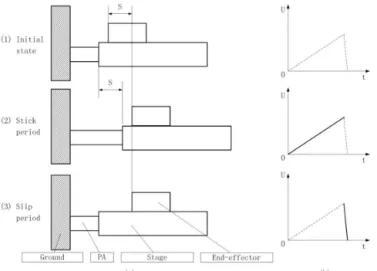
One example of the PIFA system is the well-known FDA (friction-driving actuator) (Zhang et al., 2012) (Fig. 1), which consists of the stage, the end effector, the ground (which is at rest with respect to the other components), and the PA which connects to the ground at one end and to the stage at the other end. The working principle of the FDA (Fig. 1) consists of three steps:
Figure 1. The principle of the FDA:(a)actuation steps and(b) input voltage.
2. The stick period: during this period, the input voltage increases very slowly. The PA will extend to a distance S at a very low velocity. During this period, the fric-tion force between the end effector and the stage is large enough to overcome the inertial force of the end effec-tor with respect to the stage. Therefore, the end effeceffec-tor sticks on the stage and moves forward, together with the stage, the distance S.
3. The slip period: during this period, the input voltage de-creases very quickly. The PA will contract back to the initial position in a very short time. During this period, the friction force between the end effector and the stage is not sufficiently large to overcome the inertial force of the end effector with respect to the stage. Therefore, the end effector slips on the stage and remains at its position with respect to the ground while the stage goes back to the initial position.
It is clear after the above three steps that the end effector ad-vances S without consideration of any backlash. By repeating the foregoing three steps, the end effector will keep moving forward. The driving range is only limited by the length of the stage, and it is theoretically infinite. If one changes the waveform of input voltage, the end effector will change the direction of movement.
Another well-known example of the PIFA system is an IDM (impact drive mechanism) (Soderqvist, 1976) (Fig. 2). An IDM consists of the main object, the ground, the mass block or inertial mass, and the PA that further connects to the main object at one end and to the mass block at the other. The working principle of the IDM (Fig. 2) consists of three steps.
1. The initial state: there is no input voltage applied to the PA. The PA remains at its initial length, and the main object and the mass block stay at the initial position.
Figure 2.The principle of the IDM:(a)actuation steps and(b) in-put voltage.
2. The stick period: during this period, the input voltage increases very slowly. The PA will slowly extend to a distance S, and the mass block accordingly moves for-ward a distance S at a very low velocity. During this pe-riod, the friction force between the main object and the ground is large enough to overcome the inertial force of the mass block. As such, the main object will stay at the initial position.
3. The slip period: during this period, the input voltage de-creases very quickly. The PA will contract back in a very short time. During this period, the friction force between the main object and the ground is not sufficiently large to overcome the inertial force of the mass block, and therefore the main object will slip over a distance S on the ground.
Throughout the three steps, the main object generates a dis-placement S without consideration of any backlash. If we keep repeating the foregoing three steps, the main object will keep moving forward. The driving range is only limited by the length of the ground. It should be clear that the main ob-ject will change the direction of movement if we change the waveform of input voltage.
The common elements in FDAs and IDMs are the cou-pling of the frictional and inertial effects. In fact, the gen-eral architecture of such an actuation, namely piezoelectric inertia–friction actuation (PIFA), is illustrated in Fig. 3. The PIFA system consists of four objects: A, B, C, and D. The connectivity among the four objects is such that one connec-tion is present between A and C, which is a PA in this case, and the other connection is present between A and B, which is a frictional contact.
Figure 3.The general architecture of the PIFA system. A, B, C, D (PA): the objects in the system.mA,mB,mC: the masses of the objects.Ff: the frictional force between object A and object B. PA: piezoelectric actuator.
rest with respect to the other components D), and D is the PA which connects to the ground object C at one end and to the stage A at the other. In the IDM, A is the main object; B is the ground; C is the mass block or inertial mass; and D is the PA which connects the main object at one end and to the mass block at the other end.
It should be noted that the inchworm actuator (Shamoto et al., 2000; Shamoto and Moriwaki, 1997) is different from the PIFA, so the present paper does not cover the inchworm. A detailed elaboration on the difference between the PIFA and the inchworm can be found in Zhang et al. (2012) and Ouyang et al. (2008).
On a general note, an important benefit from the general-ization of FDAs and IDMs into the general architecture of the PIFA is the opening of a potential source of innovation for new devices that combine the piezoelectric and inertia– friction principles. For instance, both FDAs and IDMs can be viewed as specific PIFAs with respect to the general archi-tecture of PIFAs. The discussion of this benefit is not within the scope of this paper, and for details the reader is directed to Zhang et al. (2012). The present paper will derive another benefit from this generalization, i.e., its facility for classify-ing the knowledge of modelclassify-ing and control of the specific types of PIFAs such as FDAs and IDMs in such a way that the general architecture serves as a common platform (i.e., the PIFA architecture) for comparison of different theories or technologies. Indeed, with this general architecture, the knowledge for PIFAs such as FDAs and IDMs can be ana-lyzed and compared, and this will also have benefits for the further development of both FDAs and IDMs.
It is well known that accurate models and feedback con-trol methods are very important in order to achieve high per-formance with dynamic systems. The models also provide a tool for the optimization of the system design. The mod-eling and control of PIFAs are difficult due to effects such as material hysteresis, creep behavior, and friction hysteresis coupled with thermal effect (if the PIFA is operated over suf-ficiently long periods of time) (Li et al., 2008). In addition, the PIFA system may concern both step movement (similar to a step motor, concerning only a step length called the nor-mal mode) and fine movement within a single step (called the fine mode or scanning mode) (Spiller and Hurak, 2011).
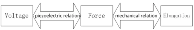
Figure 4.Internal relations of the piezoelectric actuator (no se-quence between these two relations).
Not many review papers on the problem of modeling and control are available regarding specific types of PIFAs, namely IDMs and FDAs. Nguyen et al. (2013) presented a review of the modeling of a FDA (a specific type of PIFA). However, they did not consider the dynamics of PAs, nor the dynamics of the other two moving components (except the ground object). They did, however, consider friction, but their discussion is not comprehensive in that the discussion overlooked many interesting friction models. The present pa-per attempts to overcome this shortcoming, and a discussion of future work will also be presented in the final section.
2 Modeling of PIFA systems
The dynamics of the whole system of a PIFA depend on the dynamics of both the PA and those of the frictional contact. Therefore, a dynamic model of the whole system must cap-ture the dynamics of the PA and the frictional contact (Fig. 3).
2.1 Modeling of PA
A PA converts an electrical signal into a physical displace-ment. In particular, when a voltage is applied to a piezoelec-tric material (e.g., a stack), the material will produce a sig-nificantly large deformation. By controlling the voltage, the displacement can be controlled. Therefore, the piezoelectric actuator is a coupled electrical–mechanical system. There are two basic processes (thus relations) in a PA, as shown in Fig. 4: (1) the piezoelectric relation and (2) the mechanical relation.
2.1.1 The piezoelectric relation
The piezoelectric relation is where a voltage is applied to the two ends of a piezoelectric material and the voltage gener-ates an internal force within the piezoelectric material, caus-ing the material to deform. Both the hysteresis and creep ef-fect occur during this process. Ideally, the PA model should cover these two effects. However, in the existing literature, the creep effect is mostly ignored (because the PA works with high frequency in the PIFA systems and the creep effect is very small). The present paper does not cover the creep ef-fect. The challenge in modeling of the piezoelectric relation is thus how to account for the hysteresis behavior.
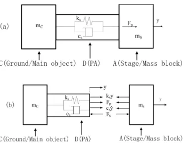
Figure 5.The spring-mass-damping system:(a)total system of the PA and A (stage/mass block) and(b)force analysis of the PA and A (stage/mass block) (Adriaens et al., 2000).
and Chen, 2011), i.e.,
F =H(V), (1)
where H represents the hysteresis effect or behavior. The relation H usually uses the Bouc–Wen (Bouc, 1967; Wen, 1976) or Preisach model (Mayergoyz, 1991). It is noted that the inclusion of the hysteresis effect in the model of theV–
F relation may lead to a significant computational overhead, which could then compromise the performance of PIFAs if a model-based feedback controller is used (Cheng et al., 2012). Therefore, there are also some studies (Furutani et al., 1997) that simply ignore the hysteresis effect. However, this may cause a large error in understanding the behavior of PAs.
2.1.2 The mechanical relation
The mechanical relation is where a force is applied to the piezoelectric material to cause a change in the length (y) of the material along the force or voltage direction. Usu-ally, in the modeling of PIFAs, the model for theF−y rela-tion uses a lumped model. Figure 5 shows a spring-mass-damping (lump) system. In Fig. 5, y represents the dis-placement of A (stage/mass block), ms represents the mass of A (stage/mass block), cs represents the damping coeffi-cient of A (stage/mass block),ks represents the stiffness of
A (stage/mass block),FSrepresent the interaction force
be-tween the PA and A (stage/mass block), and FP represents
the drive force generated by the PA.
The main differences in the mechanical relation among the existing PA models lie in how the inertia (e.g., mass) of the PA is represented. To date, there are three methods to deal with this issue in literature. The first method completely ne-glects the mass of the PA (Ha et al., 2005, 2006; Chang and Li, 1999; Jiang et al., 2000; Lambert et al., 2003; Edeler et
al., 2011). The mechanical relation with this method is rep-resented by
FP=ky+cy˙+my,¨ (2)
k=ks+kPA c=cs+cPA m=ms,
(3)
whereyrepresents the displacement of A (stage/mass block),
k represents the stiffness of the PIFA system, c repre-sents the damping of the PIFA system, m represents the mass of the PIFA system, ms represents the mass of A (stage/mass block), cs represents the damping coefficient of A (stage/mass block), ks represents the stiffness of (stage/mass block),cPA represents the PA damping coeffi-cient,kPA represents the stiffness of A (stage/mass block), andFP represents the drive force generated by the PA. It is
noted thatk,c, andmare at the system level, meaning that they are an aggregated property of the stiffness, damping, and mass of each component in the system (PA and stage/mass block in this case). In Kang (2007), some reasons for neglect-ing the mass of the PA are listed. Basically, if the mass of the PA is much less than the mass of the other PIFA components, the mass of the PA can be neglected. This situation may oc-cur with a single PA system but not in the PIFA. In a PIFA, the sizes of the PA and the other neighboring components are comparable, and this is true in particular when a micro-PIFA is considered. Therefore, for PIFAs, in most cases, the mass of the PA can be a significant factor, and it cannot be ignored. The second method is to treat the mass of the PA with a lumped model (Yakimov, 1997; Breguet and Clavel, 1998). Particularly, the mass of the PA is considered as concentrated at one point (usually the midpoint), and the mechanical rela-tion is then represented by
FP=ky+cy˙+my¨ (4)
k=ks+kPA c=cs+cPA m=ms+mPA2 ,
(5)
where the parameters are the same as those in the first method except thatmPArepresents the mass of the PA.
The third method is to treat the mass of the PA as a dis-tributed lumped system (Pozzi and King, 2003). In particu-lar, the method considers that the PA is composed ofnpieces. Every piece is treated the same way as in the second method. Thus, there are 2nequations to describe the dynamics of the PA.
Figure 6.Coulomb friction model.
2.2 Modeling of friction
There are six main models of friction used in modeling the friction in the PIFA system: the Coulomb model, the reset-integrator model, the LuGre model, the elastoplastic model, the Leuven model, and the Dahl model. Among these, the Coulomb, LuGre, and elastoplastic models are the most pop-ular ones. The literature regarding these models in PIFAs is discussed in the following.
2.2.1 Coulomb model
The expression for this model is as follows:
F =
Fc·Sgn(x˙) if x˙6=0,
Fapp if x˙=0 and Fapp< Fc (6)
Fc=µFN, (7)
whereF is the friction force,x˙ is the sliding speed,Fapp is
the applied force,FCis the Coulomb friction force,µis the
Coulomb friction coefficient (or the dynamic friction coeffi-cient), and FN is the normal force between the two contact
surfaces.
It can be observed (from the model) that the friction force only depends on the applied force Fapp and the direction of
the sliding speed x˙. It has only two values,Fc and−Fc, as shown in Fig. 6
This model cannot describe the influence of the sliding speed (viscous friction) and the transition between static fric-tion and dynamic fricfric-tion (the pre-sliding fricfric-tion and the Stribeck effect (Canudas de Wit et al., 1995) and the zero-amplitude phenomenon (Edeler et al., 2011)). Unfortunately, these factors may significantly impact the behavior and per-formance of PIFAs. Furthermore, there is also some difficulty in determining the direction of the velocity when the velocity is zero; when the velocity approaches zero, a high-frequency oscillating motion may occur.
This model was used in Chang and Li (1999), Jiang et al. (2000), Pohl (1987), Darby and Pellegrino (1997), and Okamoto and Yoshida (1998). In Pohl (1987), Darby and Pellegrino (1997), and Okamoto and Yoshida (1998), a very
Figure 7.Bristle theory (Canudas de Wit et al., 1995).
simple model for modeling of a PA (e.g., ignoring the hys-teresis of a PA) and inertia of the entire PIFA was presented. The Coulomb model was used to model the friction in these works; additionally, the simulation and experimental results were compared, and they showed the same trend between the experimental and simulation results but with a large error. It was further found that these models completely failed to pre-dict the performance of their experimental system when the frequency of the input voltage was high. It is clear that the result from these works suggests that the Coulomb model for friction in PIFAs is not adequate. Other works such as Furutani et al. (1998), Chang and Li (1999), and Jiang et al. (2000), which also used the Coulomb model for friction, did not discuss the adequacy of the Coulomb model for fric-tional contact in PIFAs.
Some modifications to the Coulomb model have been made in the existing literature. For instance, Patrascu and Stramigioli (2007) used a model for friction that was based on the Coulomb model with an empirical Stribeck effect. The entire system in Patrascu and Stramigioli (2007) was mod-eled as a simple mass-spring system. They showed that the model predicted results quite close to the experimental re-sults. This suggests the need to include the Stribeck effect in the friction model for PIFAs.
2.2.2 LuGre model
It is known from the literature that the LuGre model can usu-ally provide a relatively good result with acceptable com-plexity. This model was developed based on bristle theory (Canudas de Wit et al., 1995). In this theory, a frictional sur-face is composed of numerous elastic bristles. The frictional force arises from the interaction of the elastic bristles of the two contact surfaces, as shown in Fig. 7.
stiffness. The expression for the LuGre model is as follows:
F =σ0z+σ1dz dt +σ2v dz
dt =v−
|v|
g(v)z,
(8)
whereF is the friction force,σ0is the average stiffness of
the bristles,σ1is the damping coefficient,σ2is the viscous
coefficient, z is the average deflection of the bristles, v is the relative velocity between the two surfaces, andg(v) is a function corresponding to the Stribeck effect. Based on the experimental data from Canudas de Wit et al. (1995), the Lu-Gre model, with the exception of the hysteresis in the regions that include the pre-sliding period, has captured almost all of the important frictional characteristics such as the Stribeck effect, static friction, viscous friction, frictional lag, and pre-sliding.
The LuGre model was used in the work of Kang (2007), Breguet and Clavel (1998), Canudas de Wit et al. (1995), Bergander and Breguet (2003), Zhang (2008), and Li et al. (2009). In Bergander and Breguet (2003), a dynamic model of PIFAs was established, in which the LuGre model was used to model the friction. The goal of their study was to examine how to attenuate vibration in the PIFA so that the velocity of the PIFA could be increased (note: the velocity is restricted by the vibration). There is no direct evidence in their work to show the adequacy of the LuGre model; how-ever, the success of their method to attenuate the vibration and consequently double the velocity of the PIFA may pro-vide indirect epro-vidence of the adequacy of the LuGre model. In Kang (2007), a comparison was made between the LuGre, elastoplastic model, and reset-integrator model, based on the simulation. The comparison showed that the LuGre model was the most suitable one for their system in terms of the usability of the model.
One problem with the LuGre model is that the accuracy of the model changes with an increase in the number of opera-tions of the system. Such a phenomenon is called drift. The underlying reason for the drift is due to the plastic deforma-tion of the asperity. However, the LuGre model is unable to capture this kind of deformation.
Some modifications to the LuGre model have been made in the existing literature. In our group, Li et al. (2009) added the thermal effect into the LuGre model, and two approaches to integrate the thermal effect into the model were proposed. The first approach was to consider the parameters in the Lu-Gre model as functions of temperature. The second approach was to consider the model as having two parts: (i) the LuGre model, which corresponds to the friction force without the thermal effect, and (ii) the thermal effect, in which the tem-perature is the only variable. The two approaches were com-pared with a conclusion that the second approach is better than the first one in terms of both accuracy and computational cost. This was perhaps the first time in which the thermal ef-fect was considered in a friction model. However, the method
of Li et al. (2009) took a black-box approach to establishing a model; see (Li et al., 2009) for a more detailed discussion of the black-box model. Therefore, the model-building process is more complex, and the model accuracy is limited.
It should be noted that, in Zhang (2008), the viscous term in the LuGre model was abandoned for PIFAs. This is be-cause the author found that the viscous term has little effect on PIFA behavior, which is also due to the limited velocity with the PIFA. In short, it remains to be a future work to examine the LuGre model for its suitability for PIFAs, espe-cially to determine a coupling relation between the friction and the temperature rise at the contact surface in PIFAs.
2.2.3 Elastoplastic model
The elastoplastic model is an improvement of the LuGre model. The expression for the model is as follows:
F =σ0z+σ1 dz dt +σ2v dz
dt =v
1−α(z, v) σ0
g(v)z
i ,
(9)
whereF is the friction force;σ0 is the average stiffness of the bristles;σ1is the damping coefficient;σ2is the viscous coefficient, z is the average deflection of the bristles;v is the relative velocity between the two surfaces (which is cal-culated from the relative displacement between the two sur-faces,x, using the relationv= ˙x);xis divided into two parts:
x=z+w, wherezis the elastic part (also the deformation of the bristles) andwis the plastic part; andg(v) is a function corresponding to the Stribeck effect.α(z, v) is a parameter which is defined by
α(z, v)=
0 |z|< zba
1 2sin π
z− zmax+zba 2
zmax−zba
!
+1
2 zba< |z|< zmax
1 |z|> zmax,
(10)
wherezbais the breakaway average deflection andzmaxis the
maximum average deflection or the steady-state deflection. The improvement of the elastoplastic model over the Lu-Gre model is that elastoplastic model divides the relative dis-placement in the pre-sliding stage into two parts – the elastic partzand the plastic part w – by introducing the parame-terα(z, v). The elastoplastic model provides a more detailed description of the pre-sliding. The introduction of the notion of the breakaway average deflectionzbamay overcome the
drift problem in the LuGre model (Edeler et al., 2011). How-ever, the elastoplastic model is much more complex than the LuGre model due to the introduction of the parametersw,z, andα(z, v).
were used. According to them, there was no large difference between the two models. The authors came to the conclusion that both the Dahl and elastoplastic model are effective in representing the friction in the PIFA system. This may be be-cause the test bed they used to identify the model parameters was too coarse. They used a supporting cylinder to support the driving object. There was a friction between the support-ing cylinder and the drivsupport-ing object, which may contribute to the dynamics of the entire system; however, this friction was ignored in their work.
In Rakotondrabe et al. (2009), a state-space model of PI-FAs was presented. This model is only for one period of mo-tion. In Kang (2007), two models (the LuGre and elastoplas-tic model) were carefully compared. They concluded that the elastoplastic model is not a good choice for PIFA systems unless a sound reason is given.
Some modifications of the elastoplastic model have been made in literature. For instance, in Edeler et al. (2011), the authors performed a comprehensive investigation of the “zero-amplitude phenomenon”, and they developed a model called the “CEIM” model based on the elastoplastic model. In the CEIM model, they made an empirical modification by introducing the preload to the parameterszba,zmaxandσ0. This modification enabled the model to cover the influence of the preload at zero amplitude.
2.2.4 Leuven, reset-integrator, and Dahl models
In Ha et al. (2005), they used a combined Leuven model and Bouc–Wen model to describe the friction and friction-induced hysteresis. They showed that the friction-friction-induced hysteresis can be captured. However, how effective the Leu-ven model is at describing the friction behavior was not shown. In Fung et al. (2008a), hysteresis was considered as a characteristic of friction and not only as a characteristic of the piezoelectric materials. Certainly, both friction and the piezoelectric materials have hysteresis, and so their work is a pioneering work in the area of modeling of the PIFA. How-ever, there is no direct evidence (in their work) of the ade-quacy of the Leuven model for friction. The reset-integrator model was presented in Chao et al. (2006). They developed a feedback controller for the PIFA system. However, the per-formance of the model, in the aspect of friction modeling, was not discussed. In Chen et al. (2008), the Dahl and elasto-plastic model were compared as discussed previously.
2.2.5 Discussion
In short, the Coulomb, LuGre, elastoplastic, rest-integrator, Leuven, and Dahl models have been applied to PIFAs in the existing literature. The first three models have been widely used, and the LuGre model appears to be the most promising
For object A mAx¨A=DAFa−BAFf For object B mBx¨B=ABFf For object C mCx¨C= −DCFaP
C DFa For object D ADFa, V
=0 Following Newton’s third law B
AFf= A
BFf=F(N); C DFa=
D
CFa;ADFa= D AFa
one. However, not much attention has been to thermal effects on the friction behavior of PIFAs. Friction can cause a sig-nificant temperature rise, which may sigsig-nificantly affect the performance of PIFAs (Li et al., 2008).
2.3 Model integration
Model integration is used to integrate the PA model and the friction model for an entire PIFA system. The integration is based mainly on Newton’s law. In the following, we first pose a general model for any PIFA system based on the pro-posed general architecture (Fig. 3), and then the literature will be discussed in the context of this general model.
Fig. 8 shows a separate force diagram for each component. In Fig. 8, there is a friction forceABFfon A from B, and an actuation forceDAFa on A from D. There is a friction force A
BFfon B from A. There is an actuation force D
CFaon C from
D. There is an actuation forceADFaon D from A, and another actuation forceC
DFaon D from C. With respect to the origin
O, the positions of A, B, and C arexA,xB, andxC,
respec-tively. One end of the D has the same position as A, and the other end of D has the same position as C. The masses of the objects aremA,mB,mC, andmD. Thus, the following
equa-tions for a general PIFA system can be derived, as shown in Table 1.
There are eight equations in Table 1, with two general functions (P,F), where P is a model for the PA andF is a model for friction. A specific model of a specific PIFA is dependent on a specificP and a specificF. SpecificF refers to the different friction models that were reviewed earlier in this paper. SpecificP refers to the different models that were reviewed earlier in this paper.
In the literature, most of the models for the PIFA consider the components (except the PA) to be rigid. Further, in Adri-aens et al. (2000), both inertia and damping of a stage/mass block system, driven by the PA, were considered. The same approach can be found in Kang (2007), Zhang (2008), and Chen et al. (2008). By considering the damping, the accu-racy of the model has been improved.
re-Figure 8.Free-body diagram of the PIFA components.
Figure 9.Principle of feed-forward control.
stricted to actuations in the horizontal direction only. Fur-thermore, the previous models for PIFAs are for PIFAs with one degree of freedom and with a rigid connection between the PA and the other components. In fact, a so-called soft ac-tuation concept may be applicable to PIFAs, in which several components may be quite compliant or “soft”.
2.4 Utility of the PIFA model
The models for the PIFAs were used for the optimization of PIFA performance. For example, in the work of Darby and Pellegrino (1997), the model was used to optimize the input voltage waveform. In the work of Ha et al. (2005) and Jiang et al. (2000), the models were used for the optimization of the design of the whole PIFA system, including the structure of the components and the input waveform. Additionally, the model was used to test the feasibility of new PIFA designs in Lambert et al. (2003). In addition to the optimization of PIFA systems, a partial PIFA model (e.g., model of the PA alone) was used to develop a feed-forward controller or compen-sator for PIFAs. For instance, in the work of Ha et al. (2005), the PA model was used to compensate for the PA hysteresis in PIFAs.
3 Control of PIFA systems
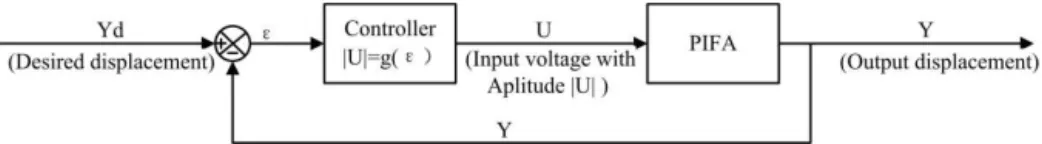
3.1 Feed-forward control
The feed-forward control is commonly used to improve the quality of the output motion of a PIFA system. This is done by compensating for the hysteresis of some components in the PIFA (e.g., PA) by designing the structure of the PIFA and/or modifying the input voltage wave to attenuate vibra-tion in the output (Holub et al., 2006). The principle of feed-forward control is shown in Fig. 9.
There are different strategies available for compensation for the hysteresis of the PA. One approach is to adjust the phase lag of the end effector (Chang and Du, 1998).
An-other strategy is to invert the hysteresis model (which rep-resents the relation between the driving force and the output displacement of the PA; Ha et al., 2005).
The feed-forward control of PIFAs is challenging because it is difficult to generate an accurate model for the PIFA. This difficulty is further due to many factors in the system, includ-ing material hysteresis, friction hysteresis, creep, vibration during the stick and slip points, and temperature rise (due to the friction, and which further changes the friction). Another difficulty arises from the inherent uncertainty in such a sys-tem, e.g., friction-induced wear of the material (Bergander et al., 2000) and thermally induced degradation of the material. There is a mechatronic technique that can be used to com-pensate for hysteresis and which uses charge control instead of voltage control (Newcomb and Flinn, 1982; Fleming et al., 2006). As such, the information flow of the system is from charge to voltage. The hysteresis occurs in the path from the voltage to the deformation. By designing the flow path from the charge to voltage, it is possible to eliminate the hysteresis from the charge to the deformation. More recently, a hybrid charge control drive was developed for PIFAs to achieve two goals (Spiller and Hurak, 2011): (1) to compensate for the hysteresis in the piezoelectric material and (2) to increase the slew rate (a fast return in voltage to achieve slip). The hybrid charge control drive is an excellent idea in that it ac-tually provides a supplemental means to compensate for the hysteresis, and since the whole system has greater means to cope with non-linear properties, the whole system gains the ability to focus on overcoming other problems, e.g., the vi-bration of the end effector.
3.2 Feedback control
Figure 10.Position feedback control with amplitudes of input voltage.
Figure 11.Position feedback control with frequency of input voltage.
for the subsequent evaluation of the output. The outcome of the evaluation is then used to adjust the control input to the (plant) system or controller itself (i.e., adaptive control).
There are two types of feedback control (of the PIFA) in the literature in terms of the output signals, namely position-ing feedback and velocity feedback. In the positionposition-ing feed-back control method, the feedfeed-back signal is the displacement of the end effector. The control input is the voltage or the charge shown in Fig. 10.
For instance, in Fahlbusch et al. (1999), the authors pre-sented a study where the output displacement information is acquired using a CCD camera with image analysis. The con-troller is a fuzzy logic concon-troller. Their approach was, how-ever, not verified by either experiment or simulation. The mo-tivation for their work was to examine the feasibility of using an image as a position sensor, as it is indeed difficult to build a sensor in PIFAs due to the limited space available in the ap-plications. In contrast, an image-based sensor is not intrusive to the system at all, which is clearly an advantage. In Shim and Gweon (2001), a laser interferometric sensor was used to obtain the displacement of the end effector, and the control input was the voltage. However, they did not describe their control law. The PIFA had three degrees of freedom, which were coupled. It is unfortunate that the experimental verifica-tion of their control system did not show much promise due to the poor construction of the test bed.
In the positioning feedback control method, the control signal could also be the frequency of the voltage (or switch-ing frequency for the PIFA in particular); see the work de-scribed in Breguet and Clavel (1998). The control strategy is shown in Fig. 11.
In Breguet and Clavel (1998), an interferometric sensor was used to measure the output displacement. The control law is a proportional one, i.e., the frequency is proportional to the displacement error. The control system enables the sys-tem to reach steady state within 2 ms without any overshoot (there is a±5 nm noise due to the resolution of the interfero-metric sensor).
A control scheme with two or more inputs has also been studied in the literature. For instance, in Rakotondrabe et al. (2008), the voltage and frequency were taken as two con-trol inputs. The output was the displacement. The concon-trol law for the two controls was a proportional law – i.e., both the amplitude and the frequency of the voltage are proportional to the displacement error.
The control strategy is shown in Fig. 12.
This control system appears to have a superior perfor-mance in the normal or stepping mode of the operation of the PIFA. However, it is not clear whether there is perfor-mance improvement in the scanning mode. The definition of stepping mode and scanning mode is mentioned in Sect. 1.
In addition to the positioning feedback control method, a velocity feedback control method has also been proposed in the literature (Chao et al., 2006). The challenge with this method was how to accurately measure the velocity informa-tion. Fortunately, there is an effect called the double piezo-electric effect (DPE), in which the PAs can provide both the position and velocity information at the same time. It is noted that the velocity information can be directly used to compen-sate for the vibration of the end effector. However, there are only a few studies in the literature that discuss the control of PIFAs using velocity information. The control strategy of velocity feedback control is shown in Fig. 13.
In Zou et al. (2005), the authors proposed a more sophis-ticated learning control method. The control law was com-posed of two parts: forward dynamics (i.e., inversion-based) and a feedback controller (proportional and iterative learn-ing). The forward dynamics were obtained using the transfer function of the system. Their approach is promising because the iterative learning controller is simple and yet provides greater enhancement of control accuracy (Chen et al., 2011; Ouyang et al., 2006). However, the PIFA does not seem to be repetitive on its own, as each step is slightly different, and the motion at the current step has some dependence on the motion at the previous steps.
Figure 12.Position feedback control with both amplitudes and frequency.
Figure 13.Velocity feedback control.
friction and hysteresis. The challenge is also due to the prin-ciple of its actuation, which consists of both the scanning mode (stick period) and step mode (slipping period). It is known that conventional feedback control is usually not suit-able for the step movement. However, the PIFA requires good feedback control for achieving reasonable accuracy and relia-bility. In the current literature, the feedback control for PIFAs is mostly model-free with a proportional control law.
4 Concluding remarks with future directions for research
4.1 Concluding remarks
This paper has presented a critical review of the work on the modeling and control of PIFAs. Modeling can be separated from control, and the model can be very useful for optimiz-ing the design of PIFAs. In this paper, modeloptimiz-ing was mainly considered useful to control, in particular for feed-forward control and compensation. To generalize the review results, this paper has also proposed a general architecture for PIFA systems. This architecture consists of a generic structure suit-able for any PIFA, that is, four components with the rela-tions among them, including the inertia-varying components, such as piezoelectric materials and friction. These compo-nents serve as templates, and an individual PIFA can be built by instantiating the template. This general architecture was useful for the systematic generation of the dynamic model of any PIFA system, as demonstrated in this paper in Sect. 1. This implies that the design of a PIFA system (including its structure and controller) can be automated by the computer. Several concluding remarks are further made in the follow-ing:
1. A dynamic model that captures all of the dynamics in-cluding friction, thermal effects, hysteresis, and vibra-tion is not currently available in the literature. Such
a model could be called a comprehensive model. It is noted that a comprehensive model would be very help-ful for feed-forward control or compensation to further improve the performance of PIFA systems (note: the comprehensive model is supposed to capture all the dy-namics of PIFAs).
2. The experimental studies of PIFAs are generally weak in the current literature, as most test beds are not well designed and the experimental data are thus not con-vincing enough; for instance the support means have changed the dynamics of the PIFA in Li et al. (2009). This has compromised the reliability of the validation of the control methods.
3. Feedback control laws are usually simple and of a pro-portional type. The dynamic model is used mostly for the purpose of compensation, especially compensating for the hysteresis of the PA material. Such a feedback system is not quite robust and does not adequately ad-dress the highly uncertain dynamics of PIFAs.
4.2 Directions for future research
First, it would be of interest to develop a computer-aided de-sign system for PIFAs. Such a system, equipped with a com-puter user interface, would greatly facilitate the design of PIFA systems. The proposed general architecture of PIFAs is a possible starting point for this computer-aided design sys-tem, as a general model for the plant is a necessity for any effective computer aiding for design and control of an under-lying plant system (Zhang, 1994; Li and Zhang, 1998).
role. Friction can consume energy in a reversible manner and can cause surface degradation. With the degradation in mind, the dynamic properties of the PIFA system are time-varying. We propose that a model-updating technique be used to up-date the model in response to degradation. Furthermore, the model-updating technique may also be expanded to the con-troller by updating the parameters in the concon-troller. This can then be called an offline adaptive controller.
Fourth, the compensation is expanded to the whole sys-tem instead of to the PA component alone. In particular, the hysteresis due to the friction (intertwined with the tempera-ture rise) needs to be compensated for. New friction models can be developed to take into account the coupling effect of friction and temperature variation (a rise in the continuous operation).
Fifth, PIFAs with different orientations and different de-grees of freedom and different configurations have wide ap-plications, such as in atom force microscopy, 3-D printing, and micro-robots. This calls for the study of control meth-ods for such PIFAs. For instance, when the direction of the output of a PIFA is vertical, the effects of gravity need to be considered as well.
Last, a relatively new concept called resilient PIFAs may be worth investigation. It is well known that PIFAs are very sensitive to disturbances, especially friction-induced degra-dation in the interface among these composing objects (A, B, C, D) (Fig. 3). This implies that PIFAs may easily suffer from malfunctioning. As such, system recovery from the dysfunc-tions of PIFAs (i.e., resilience (Zhang and Luttervelt, 2011; Zhang and Lin, 2010) is an interesting problem worthy of fu-ture research. In the recovery process, the system needs to be reconfigured and, consequently, the dynamic model for the system needs to be updated or regenerated. In this context, computer generation or automatic generation of the dynamic model for PIFAs is an essential requirement.
Acknowledgements. This work was supported by the National Natural Science Foundation of China (grant no. 51375166), Na-tional Natural Science Foundation of China (grant no. 61422310), the China Scholarship Council (CSC), and the Fundamental Re-search Funds for the Central Universities of East China University of Science and Technology. W. J. Zhang also wants to thank the NSERC for partial support for this research through a Discovery Grant.
Edited by: J. Rastegar
Reviewed by: R. Sato and one anonymous referee
Adriaens, H., De Koning, W. L., and Banning, R.: Modeling piezo-electric actuators, Mechatronics, IEEE/ASME Trans., 5, 331– 341, 2000.
Bergander, A. and Breguet, J.-M.: Performance improvements for stick-slip positioners, MHS 2003: Proceeding of 2003, Interna-tional Symposium on Micromechatronics and Human Science, Nagoya, Japan, 2003, 59–66, 2003.
Bergander, A., Breguet, J. M., Schmitt, C., and Clavel, R.: Microp-ositioners for microscopy applications based on the stick-slip effect, Mhs 2000: Proceedings of the 2000 International Sym-posium on Micromechatronics and Human Science, 213–216, doi:10.1109/Mhs.2000.903315, 2000.
Bouc, R.: Forced vibration of mechanical systems with hysteresis, Preceedings of the 4th International Conference on Nonlinear Oscillations, Prague, Czechoslovakia, p. 315, 1967.
Breguet, J. M. and Clavel, R.: Stick and slip actuators: design, con-trol,performances and applications, MHS 1998, Proceedings of the 1998, International Symposium on Micromechatronics and HumanScience, Nagoya, Japan, 1998, 89–95, 1998.
Canudas de Wit, C., Olsson, H., Astrom, K. J., and Lischinsky, P.: A new model for control of systems with friction, Automatic Con-trol, IEEE Trans., 40, 419–425, doi:10.1109/9.376053, 1995. Chang, S. and Li, S.: A high resolution long travel friction-drive
micropositioner with programmable step size, Rev. Sci. Instr., 70, 2776–2782, 1999.
Chang, S. H. and Du, B. C.: A precision piezodriven microposi-tioner mechanism with large travel range, Rev. Sci. Instr., 69, 1785–1791, doi:10.1063/1.1148842, 1998.
Chao, S. H., Garbini, J. L., Dougherty, W. M., and Sidles, J. A.: The design and control of a three-dimensional piezoceramic tube scanner with an inertial slider, Rev. Sci. Inst., 77, 063710– 063717, 2006.
Chen, X. B., Kong, D., and Zhang, Q. S.: On the dynamics of piezoelectric-driven stick-slip actuators, in: Advances in Ma-chining and Manufacturing Technology Ix, edited by: Yao, Y., Xu, X., and Zuo, D., Key Eng. Mat., 648–652, 2008.
Chen, Z., Wang, Y., Ouyang, P., Huang, J., and Zhang, W.: A novel iteration-based controller for hybrid machine systems for trajec-tory tracking at the end-effector level, Robotica, 29, 317–324, 2011.
Cheng, L., Lin, Y. Z., Hou, Z. G., Tan, M., Huang, J., and Zhang, W. J.: Integrated Design of Machine Body and Con-trol Algorithm for Improving the Robustness of a Closed-Chain Five-Bar Machine, IEEE Asme. T. Mech., 17, 587–591, doi:10.1109/Tmech.2012.2183378, 2012.
Croft, D., Shedd, G., and Devasia, S.: Creep, hysteresis, and vibra-tion compensavibra-tion for piezoactuators: Atomic force microscopy application, P. Amer. Contr. Conf., 123, 2123–2128, 2000. Darby, A. and Pellegrino, S.: Inertial stick-slip actuator for active
control of shape and vibration, J. Intel. Mat. Syst. Str., 8, 1001– 1011, 1997.
Dupont, P., Armstrong, B., and Hayward, V.: Elasto-plastic friction model: contact compliance and stiction, American Control Con-ference 2000, Proceedings of the 2000, 1072–1077, 2000. Dupont, P., Hayward, V., Armstrong, B., and Altpeter, F.:
Edeler, C., Meyer, I., and Fatikow, S.: Modeling of stick-slip micro-drives, J. Micro-Nano Mechatr., 6, 65–87, 2011.
Fahlbusch, S., Fatikow, S., Seyfried, J., and Buerkle, A.: Flexible microrobotic system MINIMAN: design, actuation principle and control. Proceeding of the 1999 IEEE/ASME, International Con-ference on Advanced Intelligent Mechatronics, Atlanta, USA, 19–23 September 1999, 156–161, 1999.
Fleming, A. J., Behrens, S., and Moheimani, S. O. R.: Inertial vibration control using a shunted electromagnetic transducer (vol 11, pg 84, 2006), IEEE-Asme. T. Mech., 11, 367–367, doi:10.1109/Tmech.2006.878790, 2006.
Fung, R.-F., Han, C.-F., and Chang, J.-R.: Dynamic mod-eling of a high-precision self-moving stage with vari-ous frictional models, Appl. Math. Model., 32, 1769–1780, doi:10.1016/j.apm.2007.06.012, 2008a.
Fung, R. F., Han, C. F., and Ha, J. L.: Dynamic responses of the impact drive mechanism modeled by the distributed parameter system, Appl. Math. Model., 32, 1734–1743, 2008b.
Furutani, K., Mohri, N., Higuchi, and T., and Saito, N.: Develop-ment of Pocket-Size Electro-Discharge Machine with Multiple Degrees of Freedom, Proceedings of the 1993 JSME Interna-tional Conference on Advanced Mechatronics, Tokyo, Japan, 2–4 August 1993, 561–566, 1993.
Furutani, K., Mohri, N., and Higuchi, T.: Self-running type electri-cal discharge machine using impact drive mechanism, Proc. Adv. Int. Mechatron. AIM, 97, 88–93, 1997.
Furutani, K., Higuchi, T., Yamagata, Y., and Mohri, N.: Effect of lubrication on impact drive mechanism, Prec. Eng., 22, 78–86, 1998.
Ha, J. L., Fung, R. F., and Yang, C. S.: Hysteresis identification and dynamic responses of the impact drive mechanism, J. Sound Vibr., 283, 943–956, 2005.
Ha, J.-L., Fung, R.-F., Han, C.-F., and Chang, J.-R.: Effects of fric-tional models on the dynamic response of the impact drive mech-anism, J. Vibr. Acoust., 128, 88–96, 2006.
Higuchi, T., Yamagata, Y., Furutani, K., and Kudoh, K.: Precise Po-sitioning Mechanism Utilizing Rapid Deformations of Piezoelec-tric Elements, Micro Electro Mech. Syst., 222–226, 1990. Holub, O., Spiller, M., and Hurak, Z.: Stick-slip based
micropo-sitioning stage for transmission electron microscope, 9th IEEE International Workshop on Advanced Motion Control, 484–487, doi:10.1109/amc.2006.1631707, 2006.
Jiang, T., Ng, T., and Lam, K.: Optimization of a piezoelectric ce-ramic actuator, Sens. Act. A: Phys., 84, 81–94, 2000.
Kang, D.: Modeling of the piezoelectric-driven stick-slip actuators, Master, University of Saskatchewan, 1–111, 2007.
Lambert, P., Valentini, A., Lagrange, B., De Lit, P., and Delcham-bre, A.: Design and performances of a one-degree-of-freedom guided nano-actuator, Robot. Comp.-Int. Manufact., 19, 89–98, doi:10.1016/S0736-5845(02)00065-0, 2003.
Li, J., Chen, X., An, Q., Tu, S., and Zhang, W.: Friction models incorporating thermal effects in highly precision actuators, Rev. Sci. Instr., 80, 045104–045106, 2009.
Li, J. W., Yang, G. S., Zhang, W. J., Tu, S. D., and Chen, X. B.: Thermal effect on piezoelectric stick-slip actuator systems, Rev. Sci. Instr., 79, 046108, doi:10.1063/1.2908162, 2008.
Li, Q. and Zhang W. J.: On methodology of using model-based rea-soning approach to intelligent CAE systems development, Eng. Appl. Artif. Intel., 11, 327–336, 1998.
Mayergoyz, I. D.: The Classical Preisach Model of Hysteresis, in: Mathematical Models of Hysteresis, Springer New York, 1–63, 1991.
Newcomb, C. and Flinn, I.: Improving the linearity of piezoelectric ceramic actuators, Electr. Lett., 18, 442–444, 1982.
Nguyen, H. X., Edeler, C., and Fatikow, S.: Modeling of Piezo-Actuated Stick-Slip Micro-Drives: An Overview, Adv. Sci. Tech-nol., 81, 39–48, 2013.
Okamoto, Y. and Yoshida, R.: Development of linear actua-tors using piezoelectric elements, Electronics and Communica-tions in Japan, Part III: Fundamental Electronic Science (En-glish translation of Denshi Tsushin Gakkai Ronbunshi), 81, 11–17, doi:10.1002/(SICI)1520-6440(199811)81:11<11::AID-ECJC2>3.0.CO;2-U, 1998.
Ouyang, P., Tjiptoprodjo, R., Zhang, W., and Yang, G.: Micro-motion devices technology: The state of arts review, Int. J. Adv. Manufact. Technol., 38, 463–478, 2008.
Ouyang, P. R., Zhang, W. J., and Gupta, M. M.: An adaptive switching learning control method for trajectory tracking of robot manipulators, Mechatronics, 16, 51–61, doi:10.1016/j.mechatronics.2005.08.002, 2006.
Patrascu, M. and Stramigioli, S.: Modeling and simulating the stick–slip motion of theµ Walker, a MEMS-based device for µSPAM, Microsyst. Technol., 13, 181–188, 2007.
Peng, J. Y. and Chen, X. B.: Modeling of Piezoelectric-Driven Stick-Slip Actuators, IEEE/ASME Trans. Mechatr., 16, 394– 399, doi:10.1109/tmech.2010.2043849, 2011.
Pohl, D.: Dynamic piezoelectric translation devices, Review of sci-entific instruments, 58, 54–57, 1987.
Pozzi, M. and King, T.: Piezoelectric modelling for an im-pact actuator, Mechatronics, 13, 553–570, doi:10.1016/S0957-4158(02)00004-1, 2003.
Rakotondrabe, M., Haddab, Y., and Lutz, P.: Voltage/frequency pro-portional control of stick-slip micropositioning systems, IEEE Trans. Control Syst. Technol., 16, 1316–1322, 2008.
Rakotondrabe, M., Haddab, Y., and Lutz, P.: Development, mod-eling, and control of a micro-/nanopositioning 2-dof stick–slip device, Trans. IEEE/ASME Mechatron., 14, 733–745, 2009. Shamoto, E. and Moriwaki, T.: Development of a
”walk-ing drive” ultraprecision positioner, Precis. Eng., 20, 85–92, doi:10.1016/S0141-6359(97)00060-3, 1997.
Shamoto, E., Murase, H., and Moriwaki, T.: Ultraprecision 6-axis table driven by means of walking drive, Cirp Annals 2000: Man-ufacturing Technology, 299–302, 2000.
Shim, J. Y. and Gweon, D. G.: Piezo-driven metrological multiaxis nanopositioner, Rev. Sci. Instr., 72, 4183–4187, 2001.
Spiller, M., and Hurak, Z.: Hybrid charge control for stick-slip piezoelectric actuators, Mechatronics, 21, 100–108, doi:10.1016/j.mechatronics.2010.09.002, 2011.
Wen, Y.-K.: Method for random vibration of hysteretic systems, J. Eng. Mech. Div., 102, 249–263, 1976.
Yakimov, V.: Vertical ramp-actuated inertial micropositioner with a rolling-balls guide, Rev. Sci. Instr., 68, 136–139, 1997.
Zhang, Q. S.: Development and Characterization of a Novel Piezoelectric-Driven Stick – Slip Actuator with Anisotropic-Friction Surfaces, M. Sc. thesis, 1–91, 2008.
(ICAM2010), 4–6, 2010.
Zhang, Z. M., An, Q., Li, J. W., and Zhang, W. J.: Piezoelectric friction-inertia actuator-a critical review and future perspective, Int. J. Adv. Manuf. Technol., 62, 669–685, doi:10.1007/s00170-011-3827-z, 2012.
Zhang, W. J. and van Luttervelt, C. A.: Towards a Resilient Manu-facturing System, Annals of CIRP, 60, 469–472, 2011.