Mădălin Costin, I on Dobrotă, I on Voncilă, I on Paraschiv
Assessment of Electromagnetic Stress in a
Perma-nent Magnet Synchronous Machine w ith
Commuta-ble Poles
The permanent magnet synchronous machine is an adequate solution in a large range of power in high performance electrical drives and energy conversion systems. I n this paper has been assessed the per-manent magnet synchronous machine electromagnetic stress for the case of stator winding with commutable poles. Based on simplified as-sumptions, an analytic relationship of the dependence of electromag-netic stress has been obtained. Numerical simulation performed for a case study confirms the validity of the theoretical approach developed.
Keyw ords: permanent magnet synchronous machine, electromagnetic stress, commutable poles, design
1. I ntroduction
The energy conversion systems play a major role in worldwide energy politics. This is a consequence by the limitation of the distribution of the classical r esources on the earth and, in addition, by the negative effects on the environment impact. An important direction is about conversion of energy with high performances elec-trical machines in modern drive. Classical elecelec-trical drives are design with DC m a-chine and induction one. A high technology is about synchronous maa-chine with excitation based on permanent magnets.
Electrical machines are treated, in literature survey, after more criteria: de-sign, control, environmental impact etc [ 1] -[ 6] , [ 8] -[ 10] .
The design of electrical machines with a minimal value of costs and consump-tion of active materials (Fe, Cu and PM-permanent magnet) is one of the now a-days problem [ 7] , [ 12] -[ 14] , but this problem must be solved by a multi-approach global optimization, where additional constraints but me tacked into consideration according to machine destination.
I n the paper is approached the problem of assessment of electromagnetic stress for a case situation of speed variation by commutable poles for a permanent magnet synchronous machine.
2. Assessment of Electromagnetic Stress for a Permanent Magnet Synchronous Machine w ith Commutable Poles
The general designing methodology of electrical machines involves, in gener-al, different steps in the order to find the desirable optimal solution according to various imposed criteria: economic criteria, dimensional one, performances etc. From this point of view, many scenarios - according to the specifics of applications - may be investigated. Due to the fact that the numbers of design methodology freedom degrees are bigger than unknown variables, additional constraints must be having into account [ 16] -[ 17] . From the electromagnetic point of view, it is fal-lows that electrical stress represented by current density J1[ A/ mm2] and linear cur-rent density A1[ A/ mm2] respectively, and magnetic stress as magnetic flux density in the air gap Bδ[ T] to be placed in a admissible range according to accumulated practical experiences in the graphical monograms [ 8] . From this point of view, the traditional design of electrical machines is strong linked by the already constructed machines. Thus, beside those constraints, the product of electrical stress -as a thermal constraint -must be chosen according to machine degree protection (I P) [ 13] , [ 14] and [ 18] :
1 22
1 3000( . .44) 3200( . .23)
mm A P I P
I J
A . (1)
Based on this restriction, the thermal flow of losses in the active part of stator winding may be estimated, according to the range [ 13] , [ 14] and [ 18] :
21
3000
(
.
.
44
)
8000
(
.
.
23
)
m
W
P
I
P
I
Q
T , (2)where the thermal flow is described by: Q1T= ρ1A1J1(ρ1-
copper
resistivity).I n the paper [ 7] has been establishing an important and useful relationship for computing of slots number per pole and phase:
1 1 1
1 1 1 1
2
cz
h
p
m
D
k
q
γ
π
. (3)where p1 - is the number of stator poles pairs, hc1- height of stator, γ1 - architec-ture factor of slot, kz1– slot factor and m1–number of phases.
By applying the above relationship for the both case of different poles, is ob-tained:
11 11 11
11 11
11 11
2
cz
h
p
m
D
k
112 12 12
12 12
12 12
2
cz
h
p
m
D
k
q
. (5)Due to the fact that the stator has the some construction, the next equalities resulting:
1 12 11
D
D
D
(6)1 12 11 c c
c
h
h
h
(7)1 12 11
m
m
m
(8)1 12 11
. (9)The poles pairs and the slot factor are different for both two situations of poles commutable:
12 11
p
p
(10)
12 11 z
z
k
k
. (11)Those particularities described by relationships (6)-(11) are important in the computing phase of electromagnetic stress. Based on this, electromagnetic stress will be computed the reference state represented by rated one.
Starting from the condition that total number of slots will be de same (despite of the situation when the number of slots per pole and phase may be different):
1 12 11
Z
Z
Z
(12)I t is resulting that:
12 12 11 11
q
p
q
p
(13)Taking into account the above relationship, relationships (4) -(5) and condi-tions expressed by relacondi-tionships (6) -(11), it is resulting:
11 12 12 12 11
11
q
k
zp
q
k
zp
(14)From de above relationship, the magnetic flux density result as:
11 12 11 12
d d
B
B
B
B
(15)Now, from relationships (4) and (5) we obtain the architecture factor of right slot:
1
)
1
(
2
11 1111
11
c z
T
Q
k
Q
(16)
1
)
1
(
2
12 1212
12
c z
T
Q
k
Q
(17)
s s z z T T
Q
Q
k
k
Q
Q
11 12 11 12 11 121
1
.
(18)I f we take into consideration the relationship (14), we get the next relation-ship for thermal flow:
s s T T
Q
Q
Q
Q
11 12 1112
.
(19)A useful relationship may be expressed between thermal flow and tempera-ture rise on the stator slot insulation:
]
40
30
[
0 01
1
s inadin in
ins
Q
, (20)where: Δ in1thickness of insulation and λin1is thermal conductivity, while in the parentheses was noticed, by practical experiences, from design machine, the max-imal values of temperature.
Based on relationship (20) the thermal flow of losses in the stator slot insulation may express as:
11 11 11 11 in in in s
Q
, (21)12 11 11 11 in in in s
Q
. (22)Taking into account the relationships (19), (21) and (22), the thermal flow of losses in the active part of stator winding becomes:
11 12 11 12 in in T T
Q
Q
. (23)All the relationships developed until now are used for a global approach, in the particularly case, a thermal one. More useful approach is the one that may ex-press the electromagnetic stress, which are very important in the design procedure of electric machine. A fundamental relationship makes the link between thermal flow and electromagnetic stress:
11 11 11 11
A
J
Q
T
(24)12 12 12 12
A
J
Q
T
(25)I f we considerate that the resistivity does not vary with temperature (ρ11= ρ12) and based on relationship (23) -(25), we obtain the next dependence:
11 12 12 11 11 11 12 12 in in
J
A
J
A
(26)Based on the least relationship, the electromagnetic stress as current density and linear current density are expressed by the next two relationships:
11 12 12 11 12 11 11 12 in in
J
J
A
A
(28)Knowing the electromagnetic stress or the dependence between them, now mechanical stress developed by electromagnetic forces may be computed.
The apparent efforts are described by [ 13] -[ 15] :
11 11 11
2
1
A
B
(29)12 12 12
2
1
A
B
(30)where Bδ1is magnetic flux density on air gap.
From relationships (26)-(29) is obtained the apparent effort:
11 12 12 11 12 11 11 12 11 12 d d in in
B
B
J
J
, (31)where Bd1 is magnetic flux density on teeth.
Or if is used the relationship of specific power losses: 2
11 11
11
J
p
J
(32)2 22 22
22
J
p
J
, (33)is obtained: 11 12 11 12 12 11 11 12 11 12 d d J J in in
B
B
J
J
p
p
. (34)Now, starting from relationship of tangential density of force:
d d z
d
t
J
B
k
B
J
f
1
2
1
1
2
1
1, (35)
the relationship (34) becomes:
11 12 11 12 12 11 11 12 11 12 d d t t J J in in
f
f
p
p
. (36)I f we want to find a relationship of tangential force of teeth, we will start from relationship [ 13] -[ 14] :
1 1 1 1 1 f T J
k
V
Q
p
, (37)where kf1= 1+ Lf1/ L is a global geometric factor (L-ideal machine length and Lf1 -frontal length of stator winding).
The ratio of Joule losses results:
12 11 12 11 11 12 11 12 12 11 f f t t J J
k
k
V
V
f
f
p
p
Because the stator remains the same (kf11= kf12), results: 12 11 11 12 11 12 12 11
V
V
f
f
p
p
t t JJ . (39)
Based on the least relation, the tangential force density becomes:
12 11 11 12 11 12 11 12 11 12 d d T T in in t t
V
V
Q
Q
f
f
. (40)The last relationship may be expressed as a dependence of speeds:
12 11 11 12 11 12 11 12 11 12 d d T T in in t t
n
n
Q
Q
f
f
. (41)From this relation may be deduced a speed dependence of speed by electro-magnetic stress: 11 12 12 11 12 11 11 11 12 12 d d T T in in t t
Q
Q
f
f
n
n
. (42)The last relationship shows, through other things, that on each speed varia-tion a reacvaria-tion of magnetically material is being n12= f(n11,μ d12/ μ d11). From this rela-tionship may be deduced the expression of magnetic permeability of teeth for a speed variation: 12 11 11 12 11 12 11 12 11 12 t t T T in in d d
f
f
n
n
Q
Q
, (43)and based on relationship of speed [ 8] :
p
f
n
60
, (44)is obtained: 12 11 12 11 11 12 11 12 11 12 t t T T in in d d
f
f
p
p
Q
Q
. (45)3. Case study on simulation of permanent magnet synchronous ma-chine
I n the above section have been deduced different relationships for assess-ment of stress for the case of adjustable speed with poles commutation method. For this situation, in this section has been considerate a case study of permanent magnet synchronous machine design with the next requirements imposed by project design theme:
Rated power: Pn= 500 [ kW] ;
Rated efficiency: ηn= 0.93[ ad.] ;
Rated power factor: cosφn= 0.92 [ ad.] ;
Pairs of poles: p= 6 and p= 8[ ad.] (for two different speeds);
Protection degree: I P 44;
I nsulation class: F.
The excitation has been design according to NeFeBr PM which has the next characteristics:
Remnant magnetic flux density: Br= 1,1 [ T] ;
Coercitive magnetic field strength: Hc= 1049[ A/ m] ;
Relative permeability: μ rPM= 1.049;
Electric conductivity σ= 0.667 [ MS/ m] .
The topology of permanent magnet synchronous machine with permanent mag-nets mounted on the rotor surface is depicted on the Figure 1.
Figure 1.Topology of permanent magnet synchronous machine
I n the above figure has been hightailed the main geometric dimensions of the machine.
I n the order to assessment the electromagnetic stress, we will perform two simulations according to design methodology [ 13] and [ 14] , when magnetic flux densities and current density are de same with different poles pairs. The once geometry is identified by the same geometric factor kf1.
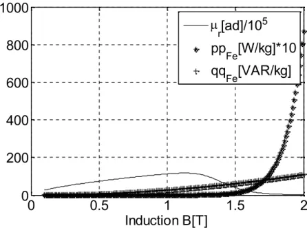
The main characteristics of magnetic steel are represented in the below Figure as a function of magnetic flux density.
cs
h
jr
h
ddo
do
m
δ
c
δ
h
D
e
D
js
0
0.5
1
1.5
2
0
200
400
600
800
1000
Induction B[T]
r
[ad]/10
5pp
Fe
[W/kg]*10
Fe
[VAR/kg]
Figure 2.Efficiency, stator current and power factor.
Thus, where hightailed the next quantities: specific active power losses ppFe[ W/ kg] , specific reactive power losses qqFe[ VAR/ kg] and relative magnetic permeability μ r. As be seen, once with increasing of magnetic flux density, the sp e-cific losses increasing too.
Now, will be represented, alternatively, the characteristics obtained for the two cases of different pairs poles.
The Efficiency, stator current and power factor are represented in Figure 3.
0 0.2 0.4 0.6 0.8 1 1.2
0 0.2 0.4 0.6 0.8 1
Load factor=p1/p1n [p.u.]
[p
.u
.]
Electromechanical characteristics
T[ad.]
A[ad.]
i1T[p.u.] i1A[p.u.]
cos1T[ad.]
cos1A[ad.]
a) p= 6
0 0.2 0.4 0.6 0.8 1 1.2
0 0.2 0.4 0.6 0.8 1
Load factor=p1/p1n [p.u.]
[p
.u
.]
Electromechanical characteristics
T[ad.]
A[ad.]
i1T[p.u.]
i1A[p.u.]
cos1T[ad.]
cos1A[ad.]
b) p= 8
From the above figure, a slight difference may be highlighted.
I mportant characteristics dependent on internal angle were represented in the Figure 4.
0 50 100 150 200
0 1 2 3 4
Inner angle[0]
[p
.u
.]
Angular characteristics
MeT[p.u.]
MeP[p.u.]
i1[p.u.]
Mmx[p.u.]
um[p.u.]
a) p= 6
0 50 100 150 200
0 1 2 3 4
Inner angle[0]
[p
.u
.]
Angular characteristics
MeT[p.u.]
MeP[p.u.]
i1[p.u.]
Mmx[p.u.]
um[p.u.]
b) p= 8
Figure 4.Characteristics dependent of internal angle
The stator geometric dimensions were represented as a function of factor kf1 in Figure 5. The curve allure is the same, but there are some slight variations ac-cording to different number of pairs poles involved.
1 1.5 2 2.5 3 3.5 4
0 0.2 0.4 0.6 0.8
Geometric dimensions of stator
Geometric factor kf1[ad.]
de [m]
d [m] l [m] hc1 [m]
hj1 [m]
a) p= 6
1 1.5 2 2.5 3 3.5 4
0 0.2 0.4 0.6 0.8 1
Geometric dimensions of stator
Geometric factor kf1[ad.]
de [m]
d [m] l [m] hc1 [m]
hj1 [m]
b) p= 8
Figure 5.Stator geometric dimensions
I n Figure 6 are represented the rotor geometric dimensions as a function of geometric factor.
1 1.5 2 2.5 3 3.5 4 -0.1
0 0.1 0.2 0.3 0.4
Geometric dimensions of rotor
Geometric factor kf1[ad.]
do [m]
ddo [m] hj2 [m] c [cm]
m [cm]
d2 [m]
a) p= 6
1 1.5 2 2.5 3 3.5 4
-0.1 0 0.1 0.2 0.3 0.4
Geometric dimensions of rotor
Geometric factor kf1[ad.]
do [m]
ddo [m] hj2 [m]
c [cm]
m [cm]
d2 [m]
b) p= 8
Figure 6.Rotor geometric dimensions
I n the order to define economic criteria for cost optimization, in Figure 7 has been represented the main curve of cost and consumption of active materials (Fe, Cu and PM).
The minimal point of total consumption cm, which will be considerate in this study, is different (different kf1).
1 1.5 2 2.5 3 3.5 4
0 0.5 1 1.5 2 2.5
3x 10 -3
Total consumption and cost of active materials
Geometric factor kf1[ad.]
cm [kg/VA]
cFe [kg/VA]
cCu [kg/VA]
cmp[kg/VA]
km [u.m./VA]/1000
a) p= 6
1 1.5 2 2.5 3 3.5 4
0 1 2 3 4x 10
-3
Total consumption and cost of active materials
Geometric factor kf1[ad.] c
m [kg/VA]
c
Fe [kg/VA]
c
Cu [kg/VA]
c
mp[kg/VA]
k
m [u.m./VA]/1000
b) p= 8
Figure 7.Specific cost and consumptions of active materials
1 1.5 2 2.5 3 3.5 4 5
6 7 8 9x 10
4 Average tangential effort
Geometric factor kf1 [ad.]
1[N/m2]
a) p= 6
1 1.5 2 2.5 3 3.5 4 5
6 7 8 9 10x 10
4 Average tangential effort
Geometric factor kf1 [ad.]
1[N/m 2
]
b) p= 8
Figure 8.Average tangential effort
I n this simulation case poles commutation leads to increase the average tan-gential efforts. All important quantities may de computed according to relationships (31), (34), (36), (40)-(43).
4. Conclusion
Speed variation, by pole commutation, generate in the intrinsic structure of electrical machines different aspect related by: stress, therm al loses and magnetic permeability variation. This aspect must be taking into account in the designing phase of electrical machines where as additional constrains must be added.
The study performed, for the case of a permanent magnet synchronous ma-chine, shows a link between main quantities as: stress, thermal losses and mag-netic permeability variation. The increasing of poles pairs leads to increasing the average tangential effort when the specific power losses (Joule one) imposed are the same
The future approach is based on the assessment of electromagnetic stress with different stator winding types.
References
[ 1] Arnold E., Die Weschselstrometchnik, Springer, Berlin, 1904 (I n Ger-man).
[ 2] Bala C., Design of Electrical Machines, Didactic and Pedagogic Publish-ing House, Bucharest, 1967 (in Romanian) .
[ 3] Boldea I .,The I nduction Machine Handbook, CRC Press, 2001.
[ 5] Boldea I .,Variabile Speed Generators, CRC Press, 2005.
[ 6] Burton T., Sharpe D., Jenkins N., Bossanyi E.,Wind Energy Handbook”, John Wiley & Sons, USA, 2001.
[ 7] Costin M., Voncila I ., Fetecau G., Optimal Selection of Slots Number per Pole and Phase of Rotational Electrical Generators, Buletinul AGI R nr.3/ 2012, iunie-august307-314.
[ 8] Cioc I ., Nica C., Design of Electrical Machines, Didactic and Pedagogic Publishing House, Bucharest, 1994 (I n Romanian).
[ 9] Dordea T., Electrical Machines, Theory, Construction, Design, Asab Publishing House, Bucharest , 2003 (I n Romanian).
[ 10] Gheorghiu I .S., Fransua A., The Treatment of Electrical Machines, vol.2, Academy Publishing House, Bucharest , 1974 (I n Romanian).
[ 11] Hansen L.H., Helle L., Blaabjerg F., Ritchie E., Munk-Nielsen S., Bind-ner H., Sørensen P., Bak-Jensen B., Conceptual survey of Generators and Power Electronics for Wind Turbines, Danemark, 2001.
[ 12] Lampola P., Directly Driven, Low-Speed Permanent -Magnet Generators forWind Power Applications, Acta Polytechnica Scandinavica, Electrical Engineering No. 1, 2000.
[ 13] Mihalache M., I nduction Machine. Analysis and Optimal Synthesis, Prin-tech Publishing House, Bucharest , 2000 (I n Romanian)
[ 14] Mihalache M., Synchronous Machine. Analysis and Optimal Synthesis, Matrixrom Publishing House, Bucharest, 2009 (I n Romanian).
[ 15] Mocanu C., Electromagnetic Field Theory, Didactic and Pedagogical Publishing House, Bucharest , 1983 (I n Romanian).
[ 16] Postnikov I ., Design of Electric Machines, State Energy Publishing House, 1954, Bucharest.
[ 17] Pyrhonen J., Jokinen T., Harabovcova V., Design of Rotating Electrical Machines, John Wiley and sons, 2009.
[ 18] Răduleţ R., Opaschi M., Design of Hydrogenerators and Synchronous Motors,Technical Publishing House, Bucharest, 1984 (I n Romanian).
Addresses:
Dr. Eng. Mădălin Costin, “ Dunărea de Jos” University of Galaţ i,
Domnească, nr. 47, 800008 – Galaţ i, România, [email protected] Assoc. Dr. Eng. I on Voncilă, “Dunărea de Jos” University of Galaţ i,
Domnească, nr. 47, 800008 – Galaţ i, România, I [email protected] Phd. Student Eng. I on Dobrotă, “Dunărea de Jos” University of Galaţ i,
Domnească, nr. 47, 800008 – Galaţ i, România, I on.Dobrotă@ugal.ro Phd. Student Eng. Asistent Profesor I on Paraschiv, “Dunărea de Jos”
University of Galaţ i, Domnească, nr. 47, 800008 – Galaţ i, România,