Electromagnetic Flux Analysis of
Permanent Magnet Brushless DC Motor
Using Magnet Software
G.R.Puttalakshmi#1, S.Paramasivam*2 #
Research Scholar, Sathyabama University, Chennai, India 1 [email protected] * Head (R&D),ESAB,Chennai,India 2 [email protected]
Abstract - Permanent Magnet Brushless DC (PMBLDC) motors is emerging as a suitable motor for a number of drive applications in industrial and consumer products. Cogging torque is one of the important drawbacks of PMBLDC motor which results in shaft vibrations and noise. The focus of this work is to minimize the electromagnetic flux and cogging torque in PMBLDC by introducing structural design modifications. The performance of the machine is analyzed by varying the magnet pole shape, magnet pole width and by using magnetic material with different remenance value. For analyzing the performance of the machine, machine is modeled using Finite Element Analysis (FEA) based software package Magnet. Cogging torque and average torque are taken as performance measures to determine optimum pole shape and pole width.
Keyword - Permanent magnet brushless dc machine, cogging torque, Finite Element Analysis, Magnet pole shape.
I. INTRODUCTION
Permanent Magnet Brushless DC (PMBLDC) motors have advantages such as high efficiency, high power density and high reliability. These motors are inherently maintenance free because of the absence of a mechanical commutator. These advantages combined with the ease of control have made them very attractive motors increasingly being used in various domestic and industrial applications. Cogging torque is one of the important drawbacks of PMBLDC motor which results in shaft vibrations and noise. The cogging torque is due to the physical structure of the machine and is produced by the magnetic attractions between the rotor mounted permanent magnets and the stator teeth. It is the circumferential component of the attractive force that attempts to maintain the alignment between the stator teeth and the permanent magnets. Cogging torque is also detrimental to the performance of position control systems such as robots and to the performance of speed control systems particularly at low speed. There are different approaches to reduce cogging torque. In some of the techniques the current wave form, injected in to the stator windings is modified. In structural solution category researchers have proposed various design modifications to minimize the cogging torque.
The focus of this work is to minimize cogging torque in PMBLDC by introducing structural design modifications. The performance of the machine is analyzed by varying the magnet pole shape, magnet pole width and by using magnetic material with different remanance value. For analyzing the performance of the machine, machine is modeled using Finite Element Analysis (FEA) based software package Magnet. Cogging torque and average torque are taken as performance measures to determine optimum pole shape and pole width.
II. COGGING TORQUE ANALYSIS
Cogging torque occurs in permanent magnet motors in the air gap between rotor and stator. As the rotor rotates, the reluctance change in the air gap due to the slots creates the cogging torque. While the magnetic flux is going through the rotor to stator, reluctance shows variation. The path of the magnetic flux begins from magnets and also rotor, and then follows air gap and stator; lastly it returns from the same way. Reluctance of the air gap is different from the steel which is used in rotor and stator. Basically the cogging torque is given by the equation.
θ
φ
d
dR
T
C g22
1
−
=
--- (1)Where
g
φ
is the air gap fluxθ
is the position of the rotor.The cogging torque can be minimized either by making airgap flux zero or the rate of change of the airgap reluctance dR/dθ zero. Airgap flux cannot be made zero therefore the cogging torque can be minimized by making the airgap reluctance to be constant with respect to rotor position [1].
The cogging torque can also be calculated from the stored energy in the air gap as a force, the stored energy in the air gap can be calculated by using the virtual work. According to this definition, the cogging torque is given by
∂
θ
∂
−
=
W
Tc
--- (2)where
W is the stored energy,
is the mechanical rotor position.
The magnetic flux and stored energy are changed with different rotor positions. The cogging torque can be rewritten in terms of flux фmand coercive force Fc
θ
φ
d
d
F
T
C c m2
1
=
--- (3)In the above equation, the magnetic flux variation causes cogging torque variation. The reduction of cogging torque by considering the ratio of pole arc to pole pitch is applicable for both Interior – magnet brushless machine and surface mounted magnet machines [2]. In axial flux Permanent Magnet machines, the cogging torque can be reduced to maximum level in skewed motor compared to non skewed motor [3]. The tooth width and slots/pole influence on uniformed teeth machine and non uniformed teeth machine is analysed [5].
The cogging torque can be minimized by several methods. Some of them are
1. Magnet shaping
2. Adding dummy stator slots 3. Shifting magnets
4. Skewing
5. Sizing
6. Teeth pairing, etc
The cogging torque can also minimized by changing the physical parameters like magnet arc, slot openings and tooth width ratio [6-7]. In this paper the shape of the pole, pole width and remenance value changed and the effect of all these is seen on the cogging torque.
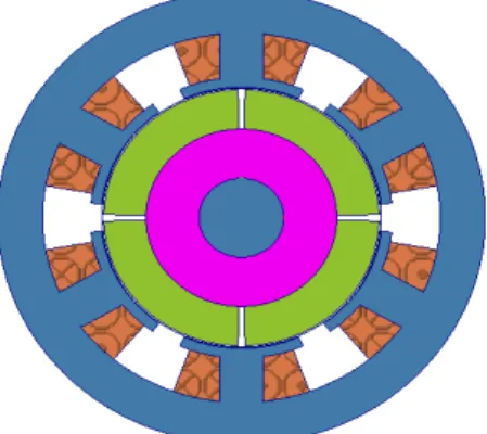
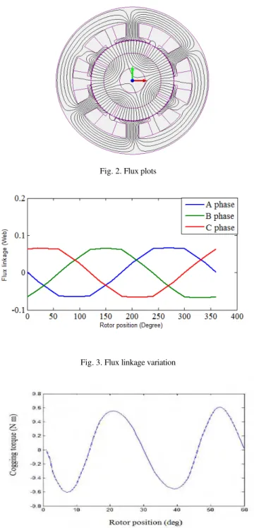
The cross section of Brushless DC Motor is shown in Fig.1. The machine parameters are specified in Appendix1. For analyzing the performance of the machine, the machine is modeled using FEA based CAD package Magnet. The flux plot, flux linkage variation and cogging torque of the motor are shown in Fig.2-Fig.4 respectively.
Fig. 2. Flux plots
Fig. 3. Flux linkage variation
Fig. 4. Cogging torque waveform for initial model
III. DESIGN EFFECTS ON COGGING TORQUE
A. Effect of stair step – Shaped magnet poles
Fig. 5(a). For Pole height of 1.5mm
Fig. 5(b). For Pole height of 0.5mm Fig. 5(c). For Pole height of 1mm.
Fig 6 shows the cogging torque comparison waveform for various stair step height. The average torque comparison for various stair step height is shown in Table 1.
Fig. 6. Cogging torque Comparison for various stair step height
TABLEI
AVERAGE TORQUE COMPARISON FOR DIFFERENT STAIR STEP HEIGHT
Height A
VERAGE TORQUE
(NM)
Initial Model 0.487209
0.25mm 0.506045
0.5mm 0.508091
The design with stair step height 0.25 & 0.5mm gives the best performance in terms of average torque and cogging torque.
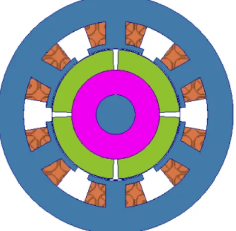
B. Effect of the magnet pole width variation
The effect of magnet pole width variation on cogging torque is analysed and optimum value is determined. The BLDC motor with different pole width is shown in Fig 7 (a & b)
Fig. 7(a). BLDC motor with magnet pole width of 5mm
Fig. 7(b). The Magnet PoleWidth of 2mm, 3mm and 4mm
Fig. 8. Cogging torque comparison for various magnet pole width
TABLEII
AVERAGE TORQUE COMPARISON FOR DIFFERENT MAGNET POLE WIDTH
Width A
VERAGE TORQUE
(NM)
Initial Model (3.0mm)
0.487209
1.0mm 0.493342 2.0mm 0.490886 5.0mm 0.459872
C. Using Different Remanance Value
In this work the performance of the machine is analyzed by introducing the different magnet materials. The materials used in this work include Neodymium Iron Boron and samarium Cobalt.
TABLEIII
AVERAGE TORQUE COMPARISON FOR USING DIFFERENT REMANANCE VALUE
Magnetic Material
AVERAGE TORQUE
(NM)
Initial Model (smco) 0.487209
NdFeB 0.483553
Fig. 9. Cogging Torque Waveform For Ndfeb – Material
Figure 9 shows the cogging torque comparison with different magnetic material. The design with NdFeB material gives the best performance in terms average torque and cogging torque.
IV. CONCLUSION
Appendix 1
BLDC Motor Parameters
PARAMETER VALUE
Magnet Thickness(mm) 8
Magnet Arc(deg) 87
Number of Phases 3
Number of Magnet Poles 4
Number of armature slots 6
Air Gap Length(mm) 0.5
Slot Opening Arc (degree) 6
Inner Radius of Rotor (mm) 18
Outer Radius of Rotor (mm) 26
Inner Radius of Stator (mm) 26.5
Radius of Stator Shoe (mm) 28.5
Radius of Stator Yoke (mm) 37.5
Outer Radius of Stator (mm) 48.5
Tooth width of Stator 8
Number of coils per
armature tooth (turn) 190
Stack Length (mm) 43
Rated Phase Current (A) 1.8
Rated Power (W) 120
Rated Speed (rpm) 3000
REFERENCES
[1] Luke Dosiek, Student Member, IEEE, and Pragasen Pillay, Fellow, IEEE “Cogging Torque Reduction in Permanent Magnet Machines”, IEEE Transactions on Industry Applications, vol. 43, no. 6, November/December 2007.
[2] Z. Q. Zhu, Senior Member, IEEE, S. Ruangsinchaiwanich, N. Schofield, and D. Howe (2003), Reduction of Cogging Torque in Interior-Magnet Brushless Machines, IEEE Transactions On Magnetics, Vol. 39, No. 5, September 2003
[3] Jong Hyun Cho, Jung Hoon Kim, Dong Ho Kim, and Yoon Su Baek School of Mechanical Engineering, Yonsei University, Seoul 120-749, Korea “Design and Parametric Analysis of Axial Flux PM Motors With Minimized Cogging Torque”, IEEE Transactions on
[4] Z. Q. Zhu, Senior Member, IEEE, S. Ruangsinchaiwanich, and David Howe” Synthesis of Cogging-Torque Waveform From Analysis of a Single Stator Slot” IEEE Transactions On Industry Applications, Vol. 42, No. 3, May/June 2006.
[5] Jiang Xintong, Xing Jingwei, Li Yong, and Lu Yongping Department of Electrical Engineering, Harbin Institute of Technology, Harbin, Heilongjiang 150001, China “Theoretical and Simulation Analysis of Influences of Stator ToothWidth on Cogging Torque of BLDC Motors”, IEEE Transactions on Magnetic, vol. 45, no.10,October 2009
[6] Y. Dönmezer and L.T. Ergene Informatics Institute, Istanbul Technical University, Istanbul, Turkey. “Cogging Torque Analysis of Interior-Type Permanent-Magnet Brushless DC Motor Used in Washers”, ELECTROMOTION 2009 – EPE Chapter ‘Electric Drives’
Joint Symposium, 1-3 July 2009, Lille, France..
[7] Daohan Wang, Xiuhe Wang, Pei, and Sang-Yong Jung,“Reducing Cogging Torque in Surface-Mounted Permanent-Magnet Motors by Non uniformly Distributed Teeth Method” IEEE Transactions On Magnetics, Vol. 47, No. 9, September 2011.