CFD Analysis of Manipulator Cabin by Selecting P roper Air
Conditioning System
Umesh S. Ghorpade
1*, Manik A. Patil
2**,Amit S. Shelake
3**,
Himanshu S. Ghodake
4**1
Assistant Professor, Sanjeevan Engineering & Technology Institute, Panhala, India 2
Assistant Professor, Sanjeevan Engineering & Technology Institute, Panhala, India 3
Assistant Professor, Sanjeevan Engineering & Technology Institute, Panhala, India 4
Student, Sanjeevan Engineering & Technology Institute, Panhala, India
ABSTRACT
Manipulator is a machine which is used to transfer heavy objects, to reduce human efforts in many industrial applications. Some of them are fully automated while some a re manually operated. It is difficu lt to work in cabin of man ipulator for the operator under hot conditions. So it is essential to provide co mfort to operator using air-conditioning system. For such applications standard air conditioners are not compatible, so we have to develop assembled system. In this paper we will be dea ling with design, selection and fa brication of co mponents like co mpressor, condenser, e xpansion device and evaporator. In order to do so, we have calculated heat load .
Keywords:
Heat load, Compressor, heat transfer coefficient, CFD.I.
INTRODUCTION
Air conditioning is concerned with the absorption of heat from where it is objectionable plus its transfer to and rejection at a place where it is unobjectionable and keeps the place comfortable for occupants. Air conditioning co mprises ma intaining te mperature, hu midity level, noise control, cleanliness. There are so many methods of air conditioning; according to situation a particular system is adopted. Usually after estimating the load standard manufactured unit is installed. Regard less of availability of various systems we need to develop a system fitting to the specific applicat ion due to co-occurrence of mult iple factor affect ing the system. As the environment of casting industry is hot, dusty, noisy, affecting the efficiency of worke rs. Now days casting industries are automated industries. They have fully mechanized conveyors for transportation of hot casting to the fettling section. To place casting fro m vibrator to conveyor manually operated manipulators are used. The working condition for the operator is largely influenced by the temperature and dust of castings. The outer temperature is around 500 C during working hours. The manipulator is not equipped
with the air conditioning facility; so it’s not
comfo rtable to the operator. The cabin of man ipulator is so compact that only a person can fit
in it and hence can’t be equipped with standard AC
system. Even we apply standard system; cabin vibrations with high amplitude causes system to fail due to unsuitable mounting. So we have developed an air conditioning system which
ma intains temperature, hu midity level, noise control and cleanliness.
II.
CALCULATION
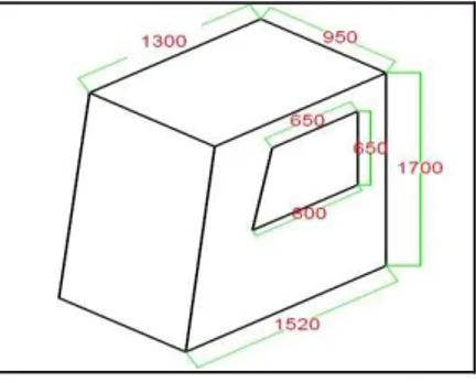
Ca lculations are required to determine the total load inside the manipulator cabin. The dimensions of the man ipulator cabin are shown in the Fig. 1.
Figure 1.Manipulator Cab in
He at Load calcul ati on.
Indoor condition: 25°C, with RH 25% - 70% and selected 60%,
The refore 25° DBT and 60% RH selected.
Outdoor condition: 50°C, with RH 30% - 40% . We will consider 42°C as the ma ximu m limit
on psychrometric chart.
Vo lu me of cabin:
Area 1= A1 = 1.7×1.3 = 2.21m2; Area 2= A2 = 0.22×1.7×0.8 = 2.27m2
Therefore, Total Area: A = A1+A 2 = 2.27+0.187 =2.457m2 (1) Volu me , V =2.457×0.950 = 2.3341 m3 (2)
Thermal conductivities:
For fiber glass, k = 0.04 W/m-K; for steel, k = 43 W/m-K
Heat transfer coefficient: Between air and glass, h = 25 W/ m2-K
Sensible heat and Latent heat; At 25° C i.e. 78° F seated very light work,
Sensible heat = 215 BTU/hr = 62.995 = 63 W and
Latent heat = 185 BTU/hr = 54.25 = 54 W
Overall heat transfer coeffic ient for g lass U:
Hence, U =4.88 W/ m2-K
(3)
Heat estimat ion:
Q = UA DT = 4.88* (50-25)* A
Through front glass window, Qf = 4.88×25×
(1.615×1/sin83) = 198.51 W (4) Through side doors , Qs = 2*Qs1
And Qs1 = Qg + Qsteel
Qg = UADT = 4.88× [(0.65×0.850) +
(0.5×150×0.001×0.850)] ×25 = 75.152 W (5)
Overall heat transfer coeffic ient for steel and glass interface U; For glass,
( 6) For steel: Fro m MS steel Eng ineering Tool bo x
we get, Ust =7.9 i.e . 8 Appr. (7)
Heat estimat ion
Area As = (2.397-0.616) = 1.781 m2 (8) Q fo r steel, Qst = 8×1.781×25 = 356.2 W. (9) Therefore, Qs1 = 75.152+356.2 = 431.352 W
And Qs = 2*Qs1 = 2×431.352 = 862.74 W. (10)
Through the rear side there is negligible heat gain due to various outer equipments mounting and noise reducing coating layer.
Occupancy Load:
The heat emitted fro m the bodies of the people also constitutes a majo r portion of a summer cooling load. The heat quantities given up by the occupants are dependent on activity of the persons, sex, age and indoor dry bulb temperature. Fro m Standard table,
Latent heat = 54 W and Sensible heat = 63 W
Therefore, Total occupancy load Qo = 117 W. (11)
Other loads;
For other heat source 10 % to 15 % of total heat load is taken.
Fresh air load estimation:
Air change per hour = 2, considering office private and no smoking.
Taking outside air 0.75 m3/ min-person Therefore, Fresh air load = 3×2 = 6 m3 /hr.
Infiltration load :
For infiltrat ion load considering 10 % of the total load
Total heat :
Q total = Qf + Qs +Qo = 198.51+ 862.70+ 117
=1178.214 W (12)
Load due to light and equipment load : Considering light load and equipment load as 20 %
of total heat load i.e .,
Light load and equipment load = 20 % Qtotal =
0.2×1178.214 = 235.64 W. (13)
On Psychrometric Chart : Following points were plotted,
A] 42° C - DBT, 40 % RH, B] 25° C - DBT, 60 % RH,
Specific volu me o f air at 1,
Vs1 = 0.92+8×10-4×3 = 0.9224 m3/ kg (14)
Infiltrated air at point 1 = 20% (Vo l)/hr = 0.2×3/ 60 = 0.02 m3/min.
Mass, ma = 0.01= 0.0108 Kg/ min (15) Fresh air =2×V =2×3 =6 m3/hr
i.e. equal to 0.1 m3/min
Enthalpy at 1 i.e. h1 = 97.5 KJ/Kg o f dry a ir, Enthalpy at 2 i.e. h2 = 5 6 KJ/ Kg of dry a ir, Enthalpy at A i.e . hA = 74 KJ/Kg of d ry air. Heat due to infiltrat ion:
i. Sensible heat gain due to infiltration a ir = ma (ha-h2) = 0.0108 (74-56)
= 0.1944 KJ/ min i.e. equal to 3.24 W. (16) ii. Latent heat due to infilt ration air = ma (h1-hA)
= 0.0108 (97.5-74)
= 0.2538 KJ/ min i.e. equal to 4.23 W. (17)
Total latent heat gain in roo m, RLH = 4.23+54 = 58.23 W. (18)
Total sensible heat gain in roo m, RSH = 3.24+63+235.64+117.214 = 1480.004. (19)
Roo m sensible heat factor, RSHF = (RSH/ RSH) + RLH =
(1480.094/ 1480.094) +58.23 = 0.9621. (20)
Align ment Circ le : Align ment circ le points are, (20% DBT, 50% RH)
Suppose for 70% return air and 30% fresh air then by trial and error method drawing line fro m 30 to 15 on saturation curve we get,
a) Bypass factor =0.157, b) td3 =28.2° C c ) td4 =17.5° C d ) td6 =15.5° C
Enthalpy at point 4 =47.3 KJ/ Kg of a ir; Enthalpy at point 3 =63 KJ/Kg of air
Mass entering room: Mass entering room, ma = RSH+RLH = 1480.09 +58.23
Therefore, ma = 0.1768 Kg/s = 10.61 kg/ min (21)
Capacity of p lant = ma (h3-h4)
Therefore, Capacity of p lant = 10.61 (63-47.3) = 166.577 KJ/ min = 0.793 TR (22)
Total load; Assuming factor of safety i.e . F.S =1.25
III.
CFD analysis
The Analysis of Manipulator cabin is carried out using Ansys14.0 software. This process consists of Three Prima ry Steps:
3.1 Pre-Processing:- This is the first step of CFD
simu lation process which helps in describing the geometry in the best possible manner. One needs to identify the fluid do main of interest.
Figure 2. Geo metry of Cab in
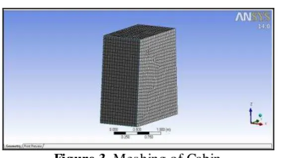
Figure 3. Meshing of Cabin
3.2 Solver: - Once the problem physics has been
identified, fluid material properties, flow physics model, and boundary conditions are set to solve using a computer.
Indoor condition: 25°C.
Outdoor condition: 50°C.
Capacity of a ir conditioner:1 TR
3.3 Post-Processing:- The next step after getting
the results is to analyze the results with different methods like contour plots, vector plot, streamlines, data curve etc. for appropriate graphical representations and report.
Figure 4. Ve locity Strea mlines
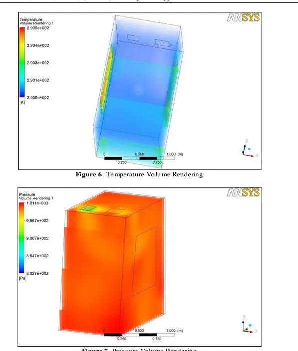
Figure 6. Te mperature Vo lu me Rendering
Figure 7. Pressure Volu me Rendering
IV.
CONCLUSION
By the study of heat load estimat ion
formulae’s, some considerations and from the basic
laws of thermodynamics the total heat load is calculated as 1 TR.
Fro m the temperature volume rendering diagra m and temperature velocity rendering diagra m we conclude that the temperature distribution inside the cabin is uniform and is under comfort zone.
REFERENCES
[1] Liu Sheng jun et.al, “Thermodynamic analysis of actual air cycle refrigerat ion
system”, System Engineering, Procedia1
(2011) 112-116.
[2] K. Nagala kshmi et.al, “The design and performance analysis of refrigerat ion system
using R-12 and R134a refrigerants”, ISSN: 2248-9622. VOL. Issue 2(Version 1), February 2014, pp.638-643.
[3] Xing Xue et.al, “Modeling and simu lation of an air cooling condenser under transient conditions”, Procedia Engineering 31 (2012) 817-822.
[4] T. S. Jadhav, “Theoretical energy saving analysis of air conditioning system using heat pipe for Indian climatic zones”,
Engineering Science and Technology,
Journal (15)669-673.
[6] A. V. Do mkundwar, “Refrigeration and Air Conditioning”, DhanpatRai Publishing House Pvt. Ltd. Reprint 2011 ISBN 978-81-7700-000-9.
[7] Abdullah A. A. a. Al-Rashid “Effect of evaporator temperature on vapour compression refrigeration system”, Ale xandria Engineering Journal (2011) 50, 283-290
[8] Isacco Stiaccini et.al “A hybrid time -frequency approach for numerica l modeling
of reciprocating compressors” Procedia
Engineering 31 (2012) 817-822
[9] Liu Jing1, PEI Qing-quing2 “Numerical Simu lation And Experimental Study of Indoors Thermal Environ ment in Su mmer Air-Conditioned Room” Procedia Engineering 52 (2013) 230-235
[10] Qi Cheng et.al. “Robust optimal design of chiller plants based on cooling load
distribution” Energy Procedia 75 (2015)
1354-1359
[11] R.K.Rajput “Air conditioning and
refrigeration” Eurasia Publishing House