INTELLIGENT NESTING SYSTEM
Zoran DJURI[I]
Montenegro Airlines Podgorica Podgorica, Serbia and MontenegroMiodrag MANI]
Faculty of Mechanical Engineering University of Ni{, Ni{, Serbia and Montenegrommanic@ban.junis.ni.ac.yu
Abstract: The economy of the process for the manufacture of parts from sheet metal plates depends on successful solution of the process of cutting various parts from sheet metal plates. Essentially, the problem is to arrange contours within a defined space so that they take up minimal surface. When taken in this way, the considered problem
assumes a more general nature; it refers to the utilization of a flat surface, and it can represent a general principle of arranging 2D contours on a certain surface. The paper presents a conceptual solution and a prototypal intelligent nesting system for optimal cutting. The problem of nesting can generally be divided into two intellectual phases: recognition and classification of shapes, and arrangement of recognized shapes on a given surface. In solving these problems, methods of artificial intelligence are applied. In the paper, trained neural network is used for recognition of shapes; on the basis of raster record of a part's drawing, it recognizes the part's shape and which class it belongs to. By means of the expert system, based on rules defined on the basis of acquisition of knowledge from manufacturing sections, as well as on the basis of certain mathematical algorithms, parts are arranged on the arrangement surface. Both systems can also work independently, having been built on the modular principle. The system uses various product models as elements of integration for the entire system.
Keywords: Nesting, neural network, expert system, product model.
1. INTRODUCTION
metal plate; from it (by means of cutting), either a finished piece or a work piece for further processing should be obtained.
As machine parts have varying shapes and dimensions, the following problem arises: how to arrange them on a sheet metal plate and cut them out so that the waste is minimal, which yields low and competitive product price on the market. This problem of arranging parts on a sheet metal plate is known in literature as nesting. It can be said that the economy of the process for the manufacture of parts from sheet metal plates in many respects depends on successful solution of the problem of nesting.
In principle, the problem can be reduced to the following: how to arrange contours within a defined space so that they take up minimal surface. When considered in this way, the problem assumes a more general nature; it refers to the utilization of a flat surface, and it can represent a general principle of arranging 2D contours on a certain surface.
Computer methods for automatic arrangement on sheet metal plates which have been developed so far have failed to yield expected results since, as a rule, the obtained degree of sheet metal plate utilization is palpably lower in automatic when compared to the interactive manner of arrangement. The reason for this is the absence of an exact mathematical algorithm for contour description, which is, in principle, an arbitrary closed curve, as well as an algorithm for arrangement. The problem is, how and in which way to model the process engineer's way of thinking during arrangement.
The work [4] presents a method of solving the pattern nesting problem on irregularly shaped stock using Genetic Algorithms (GAs), known as the evolutionary boundary nesting algorithm. This approach further generalizes the scope of the pattern nesting problem by allowing nesting on stocks of any shapes and sizes.
A large obstacle in approach to the problems of cutting was, in the first place, mathematical apparatus which prevented analytical expression of geometrical objects (each part being cut is a certain geometrical product) with complex shape, and, in the second, polysemous character of arranging all objects. The first problem was solved by a paper by V. L. Ravceva on R-function theory, which enables analytical description of objects with complex structure [10]. By means of R-functions, V. L. Rvancevu managed to solve the question of analytical description of objects and the requirement of their mutual non-intersection.
2. SYSTEM CONCEPT
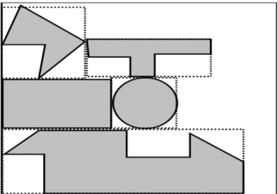
The problem of nesting is illustrated in Figure 1.
The figure clearly shows that, if possible, it is necessary to find optimal arrangement of parts on the plate so that the degree of plate material utilization is as high as possible.
By analyzing the manner in which the problem has been solved so far, the problem of nesting itself can be divided into two basic phases:
other words, the shapes are identified and classified into those parts, which are suitable for arranging and those, which are difficult to arrange.
2. The arrangement of similar or related parts on a particular surface by certain rules from experience or mathematical algorithm. In this phase the plate is being prepared for cutting and the degree of utilization of the plate is directly dependent upon it. The output of this phase is a cutting plan i.e. a cut out plate which will be processed on a classical or CNC cutting machine.
Parts to arrange
Sheet metal plate
Figure 1: Illustration of the problem
The best arrangement of parts is in most cases accomplished by applying the manual procedure i.e. by technologist's interactive work regardless of the application of numerically control machines for sheet metal cutting (CNC) and numerous developed systems for preparation of control programs. By applying interactive computer graphics, his experience and imagination, a technologist nests parts of different contours on sheet metal plates (which are usually rectangular) trying to get as high a degree of sheet metal plate utilization as possible. The degree of utilization is usually 50-60%, which means that the waste is great.
Automatic procedures mostly approximate parts of different shape into rectangles, which describe a part and have a minimal surface, and then tend to find as good a nesting of these rectangles on the sheet metal plate as possible. The procedure is illustrated in Figure 2.
The problem with this procedure is that there is no cutting of one object into another; thus the degree of utilization is smaller.
Generation of nesting options can be accomplished in two ways: 1. Empirically (experience), or
2. By following a strictly defined formalized procedure.
The first way of generating nesting options, based on the experience of an individual or group, includes procedures and attempts to arrange the elements in the nesting area in the best way. It often results in a precisely defined number of nesting diagrams, which are at the same time the cutting diagrams. This empirical approach to generating nesting options, very often does not require conducting the second phase i.e. to choosing the optimal nesting options, which is the basis for making the cutting diagrams in the plan. The drawbacks of such an approach manifest in a slightly greater waste of material in the cutting process, as well as in failing to meet the requirements for a number of cut parts and integers of the starting units of material.
The choice of nesting options, which will be the basis for making the final cutting diagrams in a cutting plan of a material, is as a rule accomplished by using the calculation procedure exclusively. This calculation procedure should provide a precise cutting diagram; by following this diagram we should obtain the required number of cut pieces, integer of starting units of material, and the minimal waste or minimal number of units of material to be cut.
The empirical choice of nesting options for cutting diagrams does not result in meeting all the requirements; therefore, a surplus (deficit) of some cut pieces, non-integer use of the starting points of material and a considerable waste may occur in the cutting process.
These solutions of the nesting problem nowadays considerably represent a great challenge for prominent scientists and industrial centers worldwide, thus the problem occupies the attention of a great number of scientists who have been trying to contribute to solving this very significant and complex problem.
With respect to the aforementioned data, a possible way for solving the problem of nesting, by applying modern methods of product modeling using CAD system, as well as the artificial intelligence methods which model the manner of work and considerations of a technologist when solving this significant problem, has been suggested in the paper. An idea, which has been tested on several examples, is presented in the paper. Every computer system, used in engineering practice for solving a problem, is basically a mathematical and logical model of the solution of the problem, presented by using computer-programming techniques and modified for the user. These models are based on analyzing the manner of solving the problem whereby mathematical, logical and empirical procedures are used in a suitable form.
The very concept of solving the nesting problem, presented in the paper, would consist of [3]:
1. Making drawings of the parts to be cut out of the sheet metal plate.
3. Arrangement of similar or related parts on a certain pre-defined surface. One or more options for arranging them can occur; among these the optimal option is chosen according to a certain criterion, degree of utilization being the most frequent.
4. Making cutting diagrams by following the chosen option, as well as the control programs for CNC machines for plate cutting. The programs can be made manually, or if the information about the part is suitable, specially developed software for generating codes for CNC control units are used.
It is necessary, therefore, to try and model this procedure by modern software tools. Since in this line of work, in addition to mathematical procedures, there are a lot of intelligent and empirical procedures, which are not subject to an exact mathematical model, methods enabling their modelling should be used.
3. NESTING SYSTEM
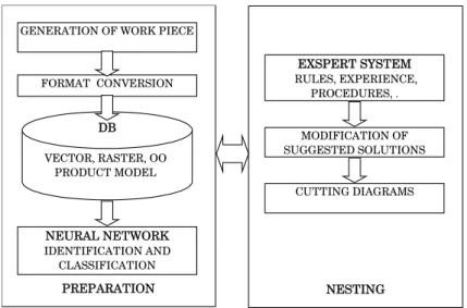
The proposed concept for nesting of sheet metal parts on a plate is based on two dominant areas of artificial intelligence: neural networks and building of expert systems. The advantages of neural networks are used to make decisions about the shape of the object and its classification. In the expert system based on the experience of technologists and their theoretical knowledge, other rules, procedures and classification of the parts, the optimal solution for nesting of parts on a sheet metal plate is proposed. In addition to this artificial intelligence technique, by using techniques for designing geometrical shapes, their modelling as well as their graphical conversion, a highly efficient nesting system is obtained. The prototypical structure of the outlined system is presented in Figure 3.
GENERATION OF WORK PIECE
FORMAT CONVERSION
DB
VECTOR, RASTER, OO PRODUCT MODEL
NEURAL NETWORK
IDENTIFICATION AND CLASSIFICATION
EXSPERT SYSTEM
RULES, EXPERIENCE, PROCEDURES, .
CUTTING DIAGRAMS MODIFICATION OF SUGGESTED SOLUTIONS
PREPARATION NESTING
The nesting system should consist of modules, which have been somehow standardized in computer engineering or developed with a special aim. It should, as well, enable the integration and uniting of the system so that it functions as an entity while at the same time communicating with other systems. By applying it, the principle of simultaneous engineering would be fully met.
A desired module of this software module should also be the module for generating the control code of CNC machines for cutting sheet metal plates. Thus, the process of designing a part and its production would be complete.
The starting point in solving this problem is a drawing of the part, which is obtained by using a CAD system. The CAD system should, in addition to drawing the part, create a model of a product that will later be used (directly or in a modified form) in identifying the shapes and their nesting on the sheet metal plate.
3.1. Modelling of contours
The first, preparatory part of the system includes the program system for designing and geometrical modelling of diverse geometrical shapes-parts, as well as the product model conversion of the geometrical-technological information about the part, which can be used in different modules. A great number of application software-CAD systems, with a more or less standard product model, can be used. In this part, regardless of the object input model (mainly a vector model), one has to follow different conversions of one format into another. After making a drawing for 2D sheet metal contour, with the application of suitable software, the object-oriented model of a sheet metal contour would be defined. For that purpose it is possible to build the option for automatic generation of the object-oriented model in the construction software that has been accepted in this paper and the software, which automatically generates the object-oriented model, has been used. In terms of the concept and in the surrounding of simultaneous engineering, it is possible to make a translator of product model, as a separate module. It would read-in the product model that has been obtained by using the appropriate software, and translate it into the object-oriented model. It should be pointed out that the translator (Figure 4) should be made for standard ways of product modelling (for example, STEP product model or IGES file).
VECTOR product model
STEP product model
RASTER product model
OO product model MODEL
TRANSLATOR
3.2. Recognitionof shape
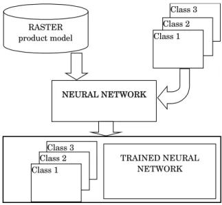
The following phase is the recognition of contour shape and classification of identified shapes, so that they could be grouped into related nesting groups. This is necessary, since in practice the forms which have something in common (for example, size, or they fall into a group of rectangular or circular objects) or belong to the same product (they are cut from the same material) are most frequently arranged together. A trained neural network has been used for identification and classification of parts in this paper. The identification itself is an extremely complicated problem from the mathematical and logical point of view. The best way to solve the problem in practice is by perception i.e. on the basis of experience and by training the staff. In order for the neural network to identify the shape, it should first be trained by the user (Figure 5).
RASTER product model
NEURAL NETWORK
Class 3 Class 2 Class 1
Class 3 Class 2 Class 1
TRAINED NEURAL NETWORK
Figure 5: Training the neural network
It would be performed in the following manner. First, rasterization of the drawing would be performed, i.e. the product model would be translated into the appropriate raster model. In comparison to the other vector or object-oriented models it is far more appropriate that the raster model be the input of a neural network, because of its binary description. There is a number of reasons for rasterization, amongst the most important are:
Rasterization does not bring about the loss of the quality of identification by neural network
The number of input neurons at the input of the network decreases considerably, thus the problem is simplified
The training period decreases.
For this procedure, software rasterizing the figure has been developed. The raster model of the part would be sent into the neural network and there it would learn about the form of the part. Information about the form would be a textual one (for example: rectangular, trapezoid, triangular etc.), or the designation of a class it belongs to would be supplied on the basis of a classifier, or both. This is a conceptual solution and, in the paper, the information about the shape of the part is only a linguistic description of the shape of the part. In the subsequent phases of the development of such systems, other ways of designating the shape of the part (for example: class) should be introduced, which would enrich the information content of part characteristics in concurrent engineering. In [3], one of the possible classifications of the parts, which could be applied in production conditions, is presented. This classification is based on the analysis of a great number of parts used in practice. The neural network would be trained to identify the shapes on a large number of examples. The trained network should identify the shape after the rasterized model of the product has been inserted. Thereafter, it would give a linguistic description, as well as the classification of the shape. The base of vector elements should serve to obtain, as we have pointed out, the object-oriented model of the product, which, in addition to the denotation of the class, is necessary for the operation of the expert system.
A three-layer back-propagation network with a hidden layer and identity linear function in the input layer, sigmoid activation function in the hidden and output layer, has been used in the paper.
In applying the training process there are different iterative training rules which are generally designed in accordance with the minimal noise principle, i.e. the adaptation of weight factors aiming at a reduction of output errors for the current training shape with a minimal noise for already adopted relations. In general terms, it can be said that the training algorithms can be regarded as parametric estimation methods. We can distinguish between two principal classes of training algorithms:
Rules of error correction which adjust the network weight factors so that the correction of error takes place at the system output for the given input shape, Gradient-based rules which adjust the network weight factors of the complete shape presentation by using the gradient fall with the aim of reducing the mean square error, averaged on the basis of the training shape:
Gradient rules should minimize the mean square error joined to the whole network of sigmoid adaptive elements.
• The square error for certain shapes is given in the expression:
[ ( )] = =
=
∑ ∑
2 2
1 1
y N T
i t i
e e t
The most efficient algorithms typically involve the presentation of a shape per a unit of time at the output of the network. That is why such an approach is called the shape learning, as opposed to the packaged learning. The mean square error for an interval is a sum of square errors of allNy, network outputs:
( ) [ ( )] = =
∑
2 2
1
y N
i i
whereby the appropriate gradient is:
( )
^ ( ) ( ) ∂ ∇ = ∂ 2 e t t w twhere denotes the vector of all network weight coefficients. The gradient fall is a process presented in the following equations:
( ) w t
( )
( )
^ ( ) ( ) ( ) µ + = + ∆ ∆ = −∇ 1w t w t w t
w t t
where µ is a training factor.
The most important relations in the training process for a passage forward through a multilayer percetron for an input-output pair p=p t( ), are given in the
following expression: = 1 2 12 T p p p
s W u s2p∈RLi
/( exp( ))
= + −
2pa 1 1 2pa
o s a=1,...,Li o20p =1 =
3 23 2
T
p p p
s W o s3p∈RNy
/( exp( ))
= + − 3
3pb 1 1 pa
o s b=1,...,Ny = 3
p p
c c
y o c=1,...,Ny
where s2p,s3pare the input vectors of the hidden and output layer of network; o2p,o3p
[ 1 (
u xL j t are the output vectors of the hidden and output layer of network; W w ,
, are network weight factors; where is a weight factor
joining neuron
)]
( )]
+
= 12 12p ijN
ij [ 23ijN
W23= w +1 u xN j
p t
tu w
j in layer t with neuron in output layer; i u; u1p represents the
network input vector (u10p =1; u
N number of network inputs); yp is the network output vector (Ny - number of network outputs).
Error square criterion is defined as:
^ . ∈ =
∑
=∑
− 2 0 5P P P
p P
E E y y
A well-known modification of the basic algorithm, which is often applied, is the algorithm of back propagation [8], [11] in which the following relation for changing weight coefficient is used.
( )
( ) η ∂ α ( )
∆ = − + ∆
∂ 1
NMij NMij
NMij E t
W y W t
W −
where α- is a constant momentum factor. The momentum factor determines the effect of the preceding changes of weight coefficients upon the current direction of changes in the domain of weight coefficients. In this way, highly frequent variations of high level of errors in the domain of weight coefficients are filtered in an effective way. Such an algorithm is in effect a low-permeability filter of the first order for gradient noise.
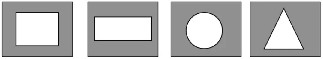
A simplified set for network training, which consists of the simplest geometrical shapes - square, circle, triangle and rectangle, is presented in Figure 6. The training shapes are presented in raster resolution.
Figure 6: Training shapes
In the course of rasterization we practically obtain a matrix of the type which consists of 0 and 1; the size of the matrix can differ depending on the resolution-meaning that at the input of the network the vector of
×
M N
= ×
L M N length as well consists of 0 and 1. The vector formed in such a manner is thereafter trained.
After the training, testing shapes (which are as well rasterized) are brought to the network input. A set of test examples is presented in Figure 7.
Identified as a triangle Identified as a square
Figure 7: Test examples of network training
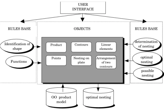
3.3. The expert nesting system
models and classes of the selected objects would be sorted out of the base. In the prototype of the expert system-EXLIM, developed on the basis of rules and procedures, the optimal nesting is suggested. It has been already pointed out that the technology of building expert systems enables the modelling and integration of theoretical and heuristic knowledge, which is very present in nesting. The base of knowledge contains certain knowledge i.e. rules which represent knowledge and the reasoning logic and work of a technologist who visually knows how to nest the parts. The rules are either heuristic (experience-related) or procedural (related to certain mathematical and algebraic rules). The user sends into the expert system those parts which neuron network has linguistically described as belonging to a certain shape. EXLIM uses the object-oriented product model as the input i.e. information, knowledge about the product for which the optimal nesting should be defined. It is obtained directly from the translator with no modifications. This enables complete integration of the two modules in CIM surrounding of a business system so that data about the product do not have to be entered twice. The object-oriented product model presents a data set about the product in the form of objects (instances), with all their characteristics and relations, in a comprehensible and natural way. The structure of the EXLIM module is presented in Figure 8.
Linear elements Contours
Arrangement of two contours Nesting on
plate Product
Points
OBJECTS RULES BASE
RULES BASE
OO product model
optimal nesting
optimal nesting Identification of
shape
Functions
determination of nesting USER
INTERFACE
possible nesting
Figure 8: Structure of the EXLIM module
characteristics of a sheet metal plate (length and width) on which the parts will be nested, are as well loaded. Depending on the read-in instances and the entered number of a part, the system identifies the presence of one or more shapes of the part. If there is only one shape of the part then it is the arrangement of the part with itself, and if there are a number of shapes then it is the arrangement of a greater number of shapes. If a part is arranged with itself, the side of the sheet metal plate along which the part will be nested (longer or shorter one), is chosen on the basis of rules in the base of knowledge. For these two possibilities there are rules with a different degree of priority and depending on its value, one of the possibilities is chosen. Then, the optimal nesting for the chosen option of arrangement is found.
For arranging two or more different shapes the procedure is:
1. First the most suitable arrangement combination, of a part with itself or two parts with each other, is found. The combination is found on the basis of square surface that describes the stack and the real surface of parts.
2. If a part is arranged with itself first the largest surface is nested, and thereafter, other parts by the falling surface. The parts can be nested along the shorter or longer side.
3. If two parts are arranged with each other, their stack is made and iterated as many times as it is required. Then, the other parts with their self are arranged on the remainder of the plate.
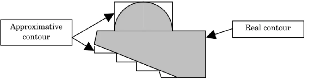
Before nesting, the identification of contours has to be performed as to investigate the possibility of arranging certain contours. What is meant by identification is that it has to be investigated whether the global shape of an object is rectangular, trapezoid, circular or some other basic or complex shape, the contour of which has been replaced by an approximative contour constituted by horizontal and vertical linear elements.
The approximations are presented in Figure 9.
Approximative
contour Real contour
Figure 9: Approximation of a contour with complex shape
Approximation of contours enables to describe the contours by using rectilinear elements in an easier way. Density of rectilinear elements in approximation depends on the real size of curvilinear parts and the required accuracy of the system.
principles, as well as the methods used to test the possibilities of nesting can, with slight alterations and additions, be applied to other basic shapes.
For rectilinear shapes identification entails the investigation of each of the outer sides of contours and determination of its configuration i.e. its topological characteristics. It is investigated whether there are some uneven edges on the side i.e. whether there are some bulges or concaves or the side is linear. We need to investigate it, since in the forthcoming research we have to decide which two sides can be arranged and under which conditions. What is meant by agreement of sides is bringing them as close as possible, with the smallest distance and gaps, in order to get as great a degree of utilization as possible. This has been presented in Figure 10.
Approximative contour k2
Approximative contour k1
Figure 10: Agreement of sides
It can be seen in the figure that it is possible to nest two contours if opposite the bulges on a part of the side of one contour there is a concave on a part of the side of the other. The size of one contour cutting into the other (i.e. their overlapping) is determined on the basis of the size of the opposed bulges and concaves.
In the forthcoming phases of developing this platform, it will be necessary to automate the classification of a part by neuron network, and develop a system, which would send certain classes into the expert system based on the modular principle and analyze particular cases.
The output of this system should be used either as a cutting diagram or in systems for automatic code generation for CNC sheet metal cutting machines.
4. IMPLEMENTATION AND EXPERIMENTAL RESULTS
The basic goal of the researches presented in this paper has been to show whether methods of artificial intelligence can be applied to the problem of nesting. For this reason, a prototypal laboratory system was created, used for testing the idea and applied methods for more successful solution of nesting.
Testing the system has shown that it is possible for a trained neural network to highly successfully recognize basic shapes and classify recognized shapes into certain classes suitable for agreement. With the increase in parts complexity, it is necessary to increase the number of examples for training, as well as the number of concealed levels of the neural network, which can make application in industrial conditions more difficult.
The developed prototypal expert system has successfully suggested arrangement for parts having rectilinear segments in contours. The obtained arrangement has a high degree of utilization, although it can be improved still further by means of manual arrangement. The purpose of a system conceived in this way can be initial arrangement, which can be improved by means of extra work.
Implementation of the system is possible in metal industry during the manufacture of parts which are cut autogenously or by means of laser from sheet metal plates, and also in textile industry when solving the problem of cutting out garments from large fabric surfaces. The second implementation is simpler to develop, bearing in mind that textile industry deals with elements which are usually standardized and typologically arranged, and which differ with respect to size only.
The applied methods, as well as the obtained experimental results during testing, indicate that this approach can be used for solving the problem of nesting. Since this is a highly complex problem, what is necessary is permanent improvement and development of the system in order to apply it in industrial conditions.
5. CONCLUSION
In the paper, the problem of identification (perception) of a shape has been solved by applying neural networks. Thus, a natural way of shape identification has been modelled. Namely, the network, by being trained on a raster product model and on a certain number of parts, becomes trained for the basic shape of the part. The trained network is thence used for identification of shapes and their classification, which is the first phase in solving the nesting problem.
arranging method, since it is based on the analysis of the object-oriented product model that brings about the modelling of theoretical and empirical (heuristic) knowledge in a united base of knowledge.
When testing such a system and its practical exploitation, as well as in further research, it might be necessary to modify some of the rules and acquire rules specific for a certain production surrounding. Methods and modules that will offer a greater number of nesting options should likewise be developed and such a system should be enriched by self-training, so that it can later offer better nesting options according to a certain predefined criterion (for example, the low degree of waste and the greater number of parts on a surface etc.).
The presented concept can, because of its prominent modularity, easily fit in the concept of simultaneous designing of products and technologies, which represents a significant problem in researches conducted in production engineering.
REFERENCES
[1] CLIPS Reference Manual, Version 6.0, NASA, 1993.god.
[2] Domazet, D., Trajanovi}, M., and Mani}, M., "CIMROT-System for concurent design, engineering and process planning of rotational parts", Proceedings of Second International Conference and Exibition on Computer Integrated Manufacturing, Singapore, 1993, 243-253. [3] \uri{i}, Z, "Primjena ve{ta~ke inteligencije u sistemima za racionalno rezanje ~eli~nih
limova", PhD Thesis, Ma{inski fakultet, Ni{, 1998.
[4] Francis, E.H., Tay, T.Y., Chong, and Lee, F.C., "Pattern nesting on irregular-shaped stock using Genetic Algorithms", Engineering Applications of Artificial Intelligence, 15 (6) (2002)
551-558.
[5] Hecth-Nilsen, R., Neurocomputing, Addison-Wesley Publishing Company, Inc., 1990.
[6] Krause, F.L., Kimura, F., Kjellberg, T., and Lu, S.C., "Product modelling", Annals of CIRP, 42
(2) (1993).
[7] Kreutzer, W., and McKenzie, B., Programming for Artificial Intelligence Methods, Tools and Applications, Addison-Wesley, 1991
[8] Lee, I.B.H., Lim, B.S., and Nee, A.Y.C., "IKOOPPS: an inteligent knowledge-based object-oriented process planning system for the manufacture of progressive dies", Expert System, 8
(1) (1991) 19-33.
[9] Mani}, M., "Ekspertni sistem za projektovanje tehnolo{kih procesa pri rezanju u obradi rotacionih delova", PhD Thesis, Ma{inski fakultet, Ni{, 1995.
[10] Rav~ev, L.V., Algebra Logiki i Integralnie Preobrazovanija v Krajevim Zada}am, Naukova
Dumila, Kiev, 1976.
[11] Rozenfeld, H., De Almedia, A.S.L., "Object oriented methodology for distributed CAPP system implementation", Proceedings of Second International Conference on Computer Integrated Manufacturing, 1 (1993) 525-535.
[12] Tello, E.R., Object-Oriented Programing fod Artificial Inelligence, A Guide to Tools and System Design, Addison Wesley, 1989.
[13] Whitlock, C., and Christofilidis, N., "An algorithm for two-dimensional cuting problems",
Operational Research, 25 (1997).