Structural and magnetic transformation of monodispersed iron oxide particles in a
reducing atmosphere
L. C. Varanda, M. Jafelicci Jr., P. Tartaj, K. O’ Grady, T. González-Carreño, M. P. Morales, T. Muñoz, and C. J. Serna
Citation: Journal of Applied Physics 92, 2079 (2002); doi: 10.1063/1.1496124 View online: http://dx.doi.org/10.1063/1.1496124
View Table of Contents: http://scitation.aip.org/content/aip/journal/jap/92/4?ver=pdfcov Published by the AIP Publishing
T. Gonza´lez-Carren˜o, M. P. Morales,a) T. Mun˜oz, and C. J. Serna
Instituto de Ciencia de Materiales de Madrid, CSIC. Cantoblanco, 28049-Madrid, Spain
~Received 22 March 2002; accepted for publication 1 June 2002!
Uniform metal iron ellipsoidal particles of around 200 nm in length were obtained by reduction and passivation of alumina-coated a– Fe2O3 ~hematite! particles under different conditions of
temperature and hydrogen flow rate. The monodispersed hematite particles were prepared by the controlled hydrolysis of ferric sulfate and further coated with a homogeneous thin layer of Al2O3by careful selection of the experimental conditions, mainly pH and aluminum salt concentration. The
reduction mechanism of a– Fe2O3 intoa–Fe was followed by x-ray and electron diffraction, and also by the measurements of the irreversible magnetic susceptibility. The transformation was found to be topotactic with the@001#direction of hematite particles, which lies along the long axis of the
particles, becoming the@111#direction of magnetite and finally the @111#direction of metal iron.
Temperature and hydrogen flow rate during the reduction have been found to be important parameters, which determine not only the degree of reduction but also the crystallite size of the final particles. Magnetic characterization of the samples shows that the only parameters affected by the crystallite size are the saturation magnetization and magnetic time-dependence effect, i.e., activation volume. © 2002 American Institute of Physics. @DOI: 10.1063/1.1496124#
I. INTRODUCTION
Advanced flexible media in the form of tapes or disks, used for the storage of digital and analog signals, consist almost exclusively of metal particles~MP!.1–3The main
rea-son for using metals and alloys for recording applications rather than oxides is that they have higher values of satura-tion magnetizasatura-tion together with high-coercive field values. Their big drawback, however, is the need for protection against oxidation, which can be achieved by controlled oxi-dation of the particle’s surface.4
The only commercially significant process for the pro-duction of iron metal particles ~MP! is the reduction of
ac-icular particles of oxyhydroxides.5,6 Silica or alumina are common elements added to the system to prevent sintering of the particles during the required heat treatment.7,8 The re-cording density achievable with these magnetic particles is limited by the coercivity and particularly the distribution of coercivities or switching fields within the material, which are closely associated with the crystallochemical characteristics of the particles~mainly, particle size distribution, coating
ho-mogeneity, and particle microstructure!.2,9 Therefore, it
seems necessary to undertake a detailed study of parameters such as heating temperature and reduction conditions to find out how these factors influence the structural and the mag-netic characteristics of the final metal particles. Previous
studies have mainly focused on the minimum temperatures required for the production of metal particles,10however, to our knowledge, no study has been made of the effect of the reduction conditions ~mainly hydrogen flow rate! on the structural and magnetic characteristics of the metal particles. The aim of this work is to study the reduction mecha-nism to a–Fe of alumina-coated microellipsoidal hematite particles, and to relate the crystallochemical characteristics of the obtained metal particles to their magnetic behavior. To reach this goal, monodisperseda– Fe2O3particles of 200 nm in length were prepared by the controlled hydrolysis of inor-ganic salts and then homogeneously coated with a thin layer of alumina. It is widely known that the controlled hydrolysis of inorganic salts can have significant advantages for the production of monodispersed fine particles with controlled microstructures,11 avoiding secondary effects from particle size or shape distributions. The use of these particles will, in addition, help to better understand the mechanisms that gov-ern the formation of metal particles. Finally, the effect of some reduction parameters such as temperature and hydro-gen flow on the crystallographic and magnetic characteristics of the final particles were investigated.
II. EXPERIMENTAL SECTION
A. Sample preparation
Reagent-grade ferric sulfate, Fe2(SO4)3•5H2O ~ Ald-rich!, aluminum nitrate, Al(NO3)3•9H2O ~Aldrich!, sodium dihydrogen phosphate, NaH2PO4~Fluka!, sodium hydroxide,
a!Author to whom correspondence should be addressed; electronic mail:
2079
NaOH~Aldrich!, and hydrochloric acid, HCl~Panreac!were
used without further purification and the solutions were pre-pared using doubly distilled water.
Monodispersed ellipsoidal hematite particles of 220
620 nm in length with an axial ratio of;6 were synthesized
following a method described earlier12 ~Fig. 1!. Fe 2(SO4)3
~0.01 moles!was dissolved in 250 mL of water to which 1 M
NaOH solution was added under stirring to reach a pH of
;10.5. The resulting brown precipitate was washed with wa-ter and the supernatant liquid was decanted. The procedure was repeated several times until a pH of;9.3 was reached. Then, 10 mL of a solution 1.0 M HCl and 4.031024 M
NaH2PO4were added to 200 mL of the suspension and aged at 10062 °C for 48 h. The product from this hydrolysis was
filtered, washed to eliminate impurities, and dried at 100 °C for 24 h.
To prevent interparticle sintering during the heating, the hematite particles were coated with aluminum oxide.13 The coating process involved first the dissolution of aluminum nitrate in 100 mL of water and then the addition of a 10% NaOH aqueous solution to reach a pH of 12.5. Hematite
particles~1.0 g!were homogeneously suspended in the solu-tion and carbon dioxide gas was blown into the slurry to lower the pH to a value of 7.5. In this way, a hydrated
aluminum oxide (Al2O3•nH2O) layer was deposited onto the surface of the hematite particles.13 Finally, the coated par-ticles were filtered, washed with water, dried, and dehy-droxylated by heating at 400 °C for 3 h. It was found that rigorous pH control was essential for the production of
ho-mogeneous alumina coatings. Thus, the initialpH was set to
12.5 because in this region, the surface of the hematite par-ticles is negatively charged, and the suspension is stabilized by electrostatic forces.14For the coating process, thepH was set to 7.5 because the isoelectric points of aluminum hydrox-ide and hematite are 9 and 6.5, respectively.14 Therefore, at
pH 7.5 the surface of the hematite particles remains
nega-tive, while the surface of the aluminum hydroxide nuclei is positively charged, favoring the heterocoagulation process and the formation of a homogenous coating. One could also start from an acidicpH, instead of basic, in order to stabilize
the hematite particles, but in this case, when increasing the
pH to the optimum value to produce heterocoagulation~7.5!, the hematite particles need to pass through their isoelectric point, which induces particle aggregation and nonneous coatings. Another parameter that affects the homoge-neity of the alumina coating is the initial concentration of the Al(NO3)3, which was found to be optimum at 1022 M. Higher concentrations drive to the segregation of aluminum
hydroxide in the form of separate particles. Meanwhile, lower concentrations result in the partial coverage of the par-ticles as detected by TEM.
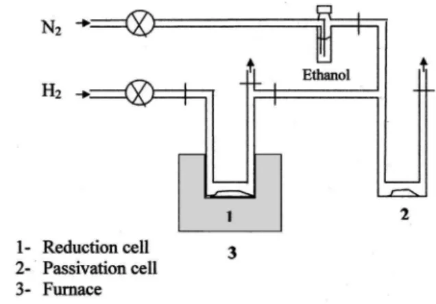
Reduction of the samples was carried out in the experi-mental setup shown schematically in Fig. 2. To study the reduction process, the alumina-coated a– Fe2O3 samples were heated at 450 °C under different flow rates of hydrogen
~from 6 to 0.2 L/h!. Aliquots were collected at different times from the reduction cell ~1! and moved into the passivation cell ~2! with a magnet, to follow phase evolution. The samples collected were cooled to room temperature under the hydrogen atmosphere. Finally, nitrogen gas was blown into a flask containing ethanol and the resulting stream was passed through the sample in order to slightly passivate the iron particle’s surface. Without passivation samples ~
espe-cially those containing the highest amount of a–Fe!rapidly
oxidized upon exposure to air.
B. Characterization techniques
Phase evolution in the samples was followed by powder x-ray diffraction~XRD!using a Philips 1710 diffractometer and Cu Ka radiation. The crystallite size of the hematite, magnetite, and metal iron particles was calculated from the full width at half maximum~FWHM!of the~104!,~311!, and ~110!reflections, respectively, using the Scherrer equation.15
The morphology, particle size, and distribution were exam-ined by transmission electron microscope~TEM, JEOL-2000
FXII!. For TEM examination the powders were dispersed in
toluene in an ultrasonic bath for one hour and then a drop of this solution was deposited onto a carbon-coated copper grid. In all cases, the average particle length and the standard de-viation were calculated by counting around 100 particles. The same microscope was used for selective area diffraction
~SAD!and high resolution imaging~HRTEM!studies on in-dividual particles.
The magnetic characterization of the samples was car-ried out in a PAR 4500 Vibrating Sample Magnetometer. Coercivity (HC) and saturation magnetization (MS) values
were obtained from the hysteresis loops at room temperature with a maximum applied field of 1 T. The samples were prepared by packing the powder into a plastic tube such that the axial ratio of the resulting sample was greater than five. In this way, the need to correct for sample shape demagne-tizing effects was avoided.
FIG. 1. Uniform hematite particles:~a!as prepared and~b!coated with an aluminum oxide layer.
FIG. 2. Experimental setup for the reduction passivation of the samples.
2080 J. Appl. Phys., Vol. 92, No. 4, 15 August 2002 Varandaet al.
a5 B f s
wherekBis Boltzmann’s constant,Tthe temperature, andHf is the fluctuation field, which represents the effect of thermal energy on the magnetization of the sample (Hf5S/xirr). In this equation, S is the coefficient of magnetic viscosity (S 52d M/d@ln(t)#) and xirr is the irreversible susceptibility, which can be obtained from the differential of the demagne-tizing remanence curve ~DCD!. DCD curves were obtained by measuring the remanent magnetization after removing a negative field applied to an initially saturated~in the positive direction!sample. In particular, the value of the irreversible susceptibility, xirr(H) obtained from the differential of the DCD curve, has also been used to follow the transformation of Fe3O4 intoa–Fe.
III. RESULTS AND DISCUSSION
A. Transformation mechanism ofa– Fe2O3 intoa–Fe
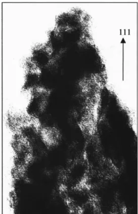
The transformation mechanism of the hematite particles to a–Fe, at 450 °C, was followed by collecting samples at different times during the reduction process~C2T series!. For this series, a hydrogen gas flow rate of 2 L/h was used. The XRD of the samples collected just after reaching 450 °C un-der the hydrogen flow~labeled as time 0!, showed only peaks due to magnetite ~Fig. 3!. At this point, electron diffraction and the corresponding high-resolution images of one particle resemble that of a single crystal with planes ~111! oriented perpendicular to the long axis of the particles~Figs. 4 and 5!.
This result clearly indicates that the transformation from he-matite to magnetite is topotactic. In particular, the direction
@001#of hematite, which lies along the long axis of the
par-ticles, becomes the@111#planes of magnetite as observed in
the high-resolution image presented in Fig. 5. The same
@111#direction along the long axis was observed for
magne-tite particles obtained from hemamagne-tite through a reduction-oxidation process.18 However, when magnetite is obtained from goethite, the long particle dimension lies along the
@110#direction.19The crystallite size of the magnetite at this
stage calculated from the~311!reflection was around 60 nm, which is similar to the crystal size calculated for the hematite precursor from the~104!reflection. Both planes form a simi-lar angle~30°!with the corresponding direction of the long particle dimension which seems to suggest that the monoc-rystaline character of the particles is preserved during the transformation from hematite to magnetite.
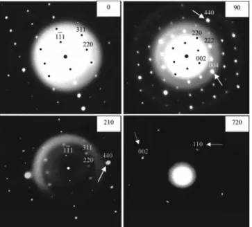
After 90 min reduction, a small peak of a iron can be observed in the XRD pattern, suggesting the onset of the transformation of magnetite toa-iron~Fig. 3!. The electron-diffraction patterns observed for several particles at this stage show single-crystal behavior ~Fig. 4!. However, the spots corresponding to the~004!and~440!planes become brighter. This effect is more pronounced for the sample reduced for
210 min ~Fig. 4!. These planes have the same interplanar
spacing ~2.07 and 1.48 Å, respectively!, as the ~110! and ~002!planes of thea–Fe structure~2.02 and 1.43 Å,
respec-tively!. Therefore, we conclude that the@001# and the@110#
directions of magnetite become the @110#and the @001#
di-rections of iron, respectively. Moreover, from these results, it can be inferred that the @111#direction of magnetite, which
lies along the long axis of the particles, becomes the @111#
FIG. 3. X-ray diffraction patterns for sample C2T at different reduction times~0, 90, 210, 390, and 600 min!.M, W, Iindicate the most intense peaks of magnetite, wustite, and iron, respectively.
FIG. 4. Electron-diffraction patterns for sample C2T at different reduction times~0, 90, 210, and 720 min!.
direction of iron, as shown in Fig. 6. Hence, it appears that the orientation of the iron particles will depend on the orien-tation of the precursor. For example, iron particles obtained from goethite will preferentially have a @001# orientation,
while iron particles obtained from hematite, as presented in this article will have a @111# orientation. In agreement with our data, different crystallographic orientations along the needle axis have been reported for iron particles such as
@001#,@111#, or@110# without specifying the reason for the discrepancy.20,21
Finally, after 720 min of reduction, the particles show an electron-diffraction pattern that resembles to that of a single crystal of a–Fe ~Fig. 4!. In this case, the crystallite size calculated from the x-ray data ~30 nm! is significantly smaller than the particle size observed by TEM (190
340 nm), suggesting that the final particles are composed of
several crystals, all of which have the same orientation within the particle.
Also, an intermediate phase has been detected and iden-tified as wustite~FeO!, in agreement with other work which postulated that the reduction of magnetite to iron goes via the intermediate wustite.22 Wustite appears after 30 min of re-duction~XRD pattern not shown!and disappears just before the end of the reduction process~600 min! ~Fig. 3!.
The reduction process was also followed by irreversible magnetic susceptibility measurements @xirr(H)# ~Fig. 7!. Given the different magnetic behavior of Fe3O4 anda–Fe, the variation ofxirr(H) as a function of the applied field for these two phases is expected to be dissimilar due to the lower contribution of the lower-shape anisotropy, and hence, coer-civity of Fe3O4, and therefore the contribution to the total
xirr(H) of both phases can be separated. The contribution of wustite to the susceptibility can be neglected due to the para-magnetic state of this oxide at room temperature. A progres-sive increase in the susceptibility due to a–Fe is observed with an increase in the reduction time~Fig. 7!. As observed,
the total transformation to iron only takes place after pro-longed heating ~720 min!. The irreversible susceptibility is
very sensitive and it is able to distinguish the contributions from a–Fe and magnetite. In fact, according to XRD ~Fig. 3!,a–Fe is almost completely formed after 600 min, how-ever, the xirr curve clearly shows that a strong magnetite component still remains in the sample~Fig. 7!. The complete reduction was also associated with an almost invariance of the MS value. TheMS values do not reach a plateau value, because as will be mentioned below, the increase in Fe crys-tallite size with the reducing time.
A correlation was found between the magnetic param-eters and the reduction time ~Table I!. As the reduction pro-ceeds thea–Fe content increases with respect to magnetite, which causes an increase in the MS value and coercivity at room temperature. However, it is important to mention that a certain contribution to the increase inMS, specially at longer times where almost no magnetite is detected, could come FIG. 5. High-resolution TEM image of magnetite formed at the beginning
of the reduction process of sample C2T (time50).
FIG. 6. Schematic representation of the topotactic transformation from he-matite to metal iron observed by electron diffraction.
FIG. 7. Irreversible magnetic susceptibility as a function of the magnetic field @xirr(H)# at different times~0, 210, 600, and 720 min! during the reduction process of sample C2T.
2082 J. Appl. Phys., Vol. 92, No. 4, 15 August 2002 Varandaet al.
from the observed increase in thea–Fe crystallite size with the reduction time~Table I!. At the beginning and at the end
of the reduction process, coercivity values are similar to those reported for ellipsoidal magnetite and iron particles, respectively.23 However, saturation magnetization values are slightly lower than those reported for magnetite and iron~80
and 220 emu/g!.23These low values can be explained by the coexistence of several effects: First, the presence of alumina does not contribute to the magnetization. Second, consider-ing the small particle size ~,200 nm!, spin canting at the surface and inside the particle can also be partially respon-sible for the observed decrease in saturation magnetization.24 Third, the presence of an iron oxide passivating layer on the particle surface does not contribute to the saturation magne-tization and has been reported to be responsible for the re-duction of the value of saturation magnetization.25
B. Structural and magnetic characteristics ofa–Fe
particles
Pure metal particles were obtained by reduction of the alumina-coated hematite particles at different temperatures and under different hydrogen flow rates. For the hydrogen flow rates used in this work, temperatures higher than 400 °C were required to obtain pure iron particles. At lower tempera-tures, a mixture of metal iron and magnetite was always found. As expected, the necessary heating times~at 450 °C!
to achieve the full reduction of the particles were inversely proportional to the hydrogen flow rate. Thus, heating times between 4 and 12 h were needed to complete the reduction when the hydrogen flow rate was varied from 6 to 2 L/h
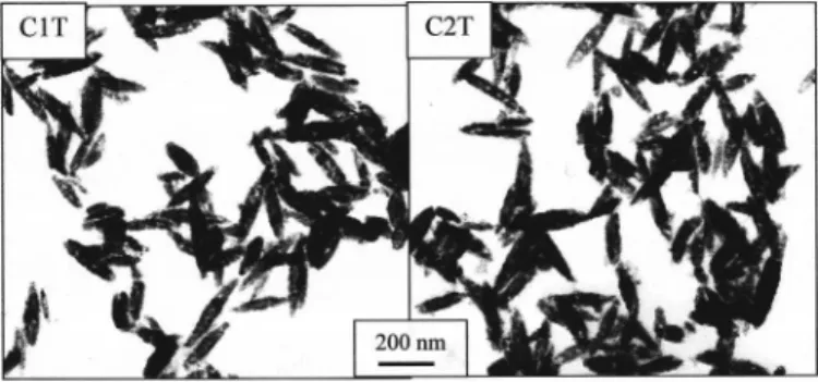
~samples C1T and C2T, respectively!. At these flow rates, the particle size and shape were only slightly altered during the transformation, as observed in Fig. 8. Thus, metal particles obtained under these conditions~samples C1T and C2T! con-sisted of ellipsoidal particles of ;190 nm in length and 40 nm in width, which means that there was a reduction in volume of around 15% during the transformation of the
a– Fe2O3particles toa–Fe. A higher reduction in volume of around 60% would have been expected from the different density of these two phases, which is ;5 and 8 g/cm3 for hematite and iron, respectively. In this case, the formation of pores inside the particles, clearly observed by TEM~Fig. 8!, justify the small reduction in size. Significant changes in morphology and particle size were observed when using a
lower-hydrogen flow rate, 0.6 L/h~sample C3T!and 0.2 L/h ~C4T!. As a consequence of the longer annealing times for
complete reduction ~24 and 96 for sample C3T and C4T,
respectively!some particles appeared broken and were
sin-tered, showing round edges under the microscope ~data not
shown!.
The kinetic of the reduction processes were followed by comparing the relative intensities of the x-ray diffraction peaks~110!ofa–Fe and~311!of Fe3O4as a function of the reduction time ~Fig. 9!. It is clear that there is a continuous transformation for samples C2T and C3T. However, in the case of sample C1T, the transformation from magnetite to iron is almost complete after a reduction of 30 min. This sharp increase in the intensity of the diffraction peaks for
a–Fe for sample C1T in the first stage of the reduction sug-gests a violent change in the structure. The crystallite size of thea–Fe particles at the end of the reduction process was 22 nm, significantly smaller that the crystallite size obtained un-der a lower-hydrogen flow rate ~Table II!. It seems that the number ofa–Fe crystallites inside the particle varies directly with the flow rate of hydrogen~i.e., with the annealing time!
and therefore this experimental parameter determines the crystallite size of the final particles. Unfortunately, the hy-drogen flow rate also determines the particle morphology, which can be significantly altered when the flow rate is so small that the heating time required to obtain pure metal iron is very long.
0 0 48 160
90 20 51 180
210 25 56 225
600 28 105 555
720 30 120 885 FIG. 8. Metal iron particles obtained at 450 °C under different hydrogen flow rates~samples C1T and C2T!.
FIG. 9. Relative intensities of the x-ray diffraction peaks~110!ofa–Fe and ~311!of Fe3O4for samples C1T, C2T, and C3T as a function of the reduc-tion time.
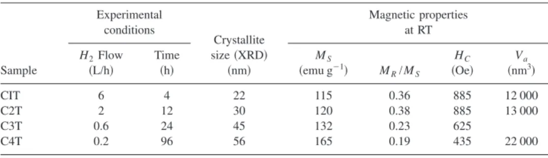
The hysteretic parameters obtained from the magnetiza-tion curves of the metal particles reduced at 450 °C under different hydrogen flow rates are included in Table II. The saturation magnetization increases as the crystallite size in-creases due to the reduction in surface area, which means not only a lower proportion of an iron oxide passivation layer with respect to metal iron, but also a lower surface canting of the magnetic moments. In contrast, the squareness decreases as the crystallite increases from samples C1T and C2T to samples C3T and C4T, suggesting incoherent rotation of the magnetization for the final two samples. The lowest values of coercivity were obtained for sample C4T with the highest crystallite size ~56 nm!. However, the same coercivity~885 Oe! was obtained for samples C1T and C2T with different crystallite sizes. This result suggests that there are two fac-tors affecting the coercivity in these samples. The first is the increase in the crystallite size from sample C1T to sample C2T, which gives rise to an increase in the coercivity. The second is the slight modification of the morphology during the reduction, which is expected to be more pronounced for sample C2T than for sample C1T due to the longer heating time. It should be noted that in this material, the coercivity is almost entirely determined by the shape anisotropy of the iron core24and therefore, the lost of acicularity gives rise to a decrease in the coercivity.
The effect of thermal activation on the switching process is more pronounced as the crystal size decreases. The activa-tion volumes calculated from time-dependence measure-ments at fields around the coercivity are given in Table II. The activation volume of reversal for all the samples are smaller than the physical volume of the particles, as deter-mined from TEM pictures, by a factor of about ten and in-creases with the crystallite size ~Table II!. This value of the activation volume corresponds to a coherent reversal volume of diameter around 23 nm for samples C1T and C2T, which agrees well with the crystallite size calculated from x-ray diffraction. For sample C4T, the corresponding dimension is 28 nm, which is half the calculated crystallite size, support-ing our view of incoherent rotation of the magnetization in this sample.
IV. CONCLUSIONS
It was found that the use of monodispersed alumina coated a– Fe2O3 microellipsoidal particles is specially ad-equate to study both the transformation of iron oxide into
a–Fe and to determine the influence of processing
condi-tions on the magnetic behavior of the final metal particles. It was found that the transformation of a– Fe2O3 into a–Fe proceeds in three stages with magnetite and wustite as reac-tion intermediates. Selective area electron-diffracreac-tion pat-terns showed that the transformation is topotactic with the orientation of the final iron particles depending on the orien-tation of the precursor. Finally, it can be concluded that in order to obtain a sample with high magnetization and high coercivity, the hydrogen flow rate used in the reduction should be optimized. It should be low to produce the mini-mum number of iron nuclei within the magnetite particle but high enough to avoid the growth of the iron nuclei above the critical single domain size.
ACKNOWLEDGMENTS
This work was supported by the CICYT under Project No. PB98-0525. Also, Dr. M.P. Morales, L.C. Varanda, and P. Tartaj gratefully acknowledge the Domingo Martinez Foundation, the Brazilian agency FAPESP, and the Royal Society, respectively, for financial support.
1M. P. Sharrock, IEEE Trans. Magn.36, 2420 ~2000!.
2K. O’Grady and H. Laidler, J. Magn. Magn. Mater.200, 616 ~1999!.
3S. Hisano and K. Saito, J. Magn. Magn. Mater.190, 371~1998!. 4S. Onodera, H. Kondo, and T. Kawana, MRS Bull.21, 28~1996!. 5N. Sugita, M. Mackawa, Y. Ohta, K. Okinaka, and N. Nagai, IEEE Trans.
Magn.31, 2854~1995!.
6M. Kishimoto, T. Nakazumi, N. Otani, and T. Sueyoshi, IEEE Trans.
Magn.27, 4645~1991!.
7R. J. Veitch, A. Ilmer, W. Lenz, and V. J. Richter, J. Magn. Magn. Mater.
193, 279~1999!.
8M. P. Morales, S. A. Walton, L. S. Prichard, C. J. Serna, D. P. E. Dickson,
and K. O’Grady, J. Magn. Magn. Mater.190, 357~1998!.
9M. P. Morales, C. J. Serna, K. O’Grady, L. S. Prichard, J. A. Hutching, G.
H. Milford, and D. P. E. Dickson, J. Magn. Magn. Mater.193, 314~1999!.
10A. A. Van der Giessen and C. J. Klomp, IEEE Trans. Magn.5, 317 ~1969!.
11E. Matijevic, Chem. Mater.5, 412 ~1993!.
12M. Ozaki, S. Kratohvil, and E. Matijevic, J. Colloid Interface Sci.102,
146~1984!.
13S. Hisano, K. Saito, S. Aizawa, K. Sano, K. Matsumoto, and K. Murata,
US Patent No. 5591535,~1997!.
14G. Parks, Chem. Rev.39, 177~1965!.
15L. V. Aza´roff, Elements of X-ray Crystallography~McGraw-Hill, New
York, 1968!p. 549.
16A. M. de Witte, K. O’Grady, G. N. Coverdale, and R. W. Chantrell, J.
Magn. Magn. Mater.88, 183~1990!.
17P. Gaunt, J. Appl. Phys.59, 4129~1986!.
18M. P. Morales, C. Pecharroma´n, T. Gonza´lez-Carren˜o, and C. J. Serna, J.
Solid State Chem.108, 158~1994!.
19R. M. Cornell and U. Schwertmann,The Iron Oxides. Structure,
Proper-ties, Reactions, Occurrence and Uses~VCH, Weinheim, 1996!.
20F. E. Luborsky, E. F. Koch, and C. R. Morelock, J. Appl. Phys.34, 2905 ~1963!.
TABLE II. Crystallite size and magnetic parameters of metal particles reduced at 450 °C under different hydrogen flow rates.
Sample
Experimental conditions
Crystallite size~XRD!
~nm!
Magnetic properties at RT
H2Flow ~L/h!
Time ~h!
MS
~emu g21! M R/MS
HC
~Oe!
Va
~nm3 !
CIT 6 4 22 115 0.36 885 12 000
C2T 2 12 30 120 0.38 885 13 000
C3T 0.6 24 45 132 0.23 625
C4T 0.2 96 56 165 0.19 435 22 000
2084 J. Appl. Phys., Vol. 92, No. 4, 15 August 2002 Varandaet al.