Meriem Benhaddi1, Karim Baïna2 and El Hassan Abdelwahed3
1
Faculty of Sciences Semlalia, Cadi Ayyad University PO.Box 2390, Marrakesh, Morocco
2
ENSIAS, Mohammed V Souissi University PO.Box 713 Agdal-Rabat, Morocco
3
Faculty of Sciences Semlalia, Cadi Ayyad University PO.Box 2390, Marrakesh, Morocco
Abstract
The end user service development known as the user-centric SOA emerged as a new approach that allows giving the end user the ability to create on the fly his own applications that meet a situational need. In fact, the classical SOA was designed for developers and is characterized by a heavy technical stack which is out of reach of end users. Lightweight Web 2.0 technologies such as Mashup appeared to bridge this gap and provide a new agile and quick way to compose and integrate different resources in a dynamic and on the fly manner. However, Mashups are emerging applications, and thus consist of immature, non intuitive and non formalized area. In this paper, we formalize the user-centric SOA development by proposing a new cloud-based architecture for user-centric SOA platforms, and by introducing a new rich integration language based on the advanced Enterprise Integration Patterns (EIPS). We also propose a new intuitive and self-explanatory semantic process for end users services integration.
Keywords: SOA, Mashup, integration patterns, end user development, end user satisfaction, intuitiveness, Cloud Computing.
1. Introduction
The text must be in English. Authors whose English language is not their own are certainly requested to have their manuscripts checked (or co-authored) by an English native speaker, for linguistic correctness before submission and in its final version, if changes had been made to the initial version. The submitted typeset scripts of each contribution must be in their final form and of good appearance because they will be printed directly. The document you are reading is written in the format that should be used in your paper.
1.1 Problems and limitations of SOA
The concepts behind the Service Oriented Architecture has proved that it is the best way to urbanize the enterprise information system by modulating applications as interoperable services; in fact SOA promotes the modulating applications as fine or coarse grained services, the reuse of services to build more complexes ones, the interoperability between different heterogeneous system, and the standardized languages and protocols (WSDL, SOAP, BPEL). SOA’s goal is to lower costs and make information systems more flexible. Nevertheless, enterprises that applied SOA didn’t get the great promised added value, which has prevented the installation of the global SOA, and has lowered the percentage of companies planning the SOA [9].
In this section, we introduce the concept of "End User", to signify the non-computer user, who has very little computer knowledge. We will give a further definition of this concept in the next section.
• The limitations of SOA could be summarized as: • Exclusion of the end user from the hierarchy of the
SOA actors: users kept away and out of the loop. In fact, the SOA technologies (WSDL, SOAP, SCA, BPEL, etc) are hard to master and require advanced knowledge [22] [28].
• Rigidity, heaviness and incompatibility of SOA implementations with the real constraints of end users:
o Lack of accessibility: UDDI registries are dedicated to expert; therefore, end users have to browse different web sites in order to use services. [17] states that SOA was originally designed as an architecture focused fundamentally on the B2B context, and does not offer support for B2C interactions.
the use of WS* technologies (WSDL, SOAP, UDDI), which prevents the development of SOA specifications, that are independent of any technology.
o Lack of flexibility and scalability: SOA technologies cannot support the services composition on the fly: After composition design, implementation, testing and deployment, it becomes very difficult to change the composition logic according to the changing needs of users, as it involves a long life cycle [18].
o Lack of mobility: SOA implementation and integration technologies are very heavy for devices with limited capabilities. WSDL and SOAP are instances of complicated XML documents, which makes the WS* services very demanding in terms of computing power, bandwidth and storage [10].
1.2 End users: Who are they? What do they need?
Definition of end user: A software end user is a person who interacts with information systems solely as a final information consumer. It’s a user with minimal technical knowledge, and who uses the software in the context of daily life or daily work for personal (business or leisure) purposes, without having any intentions to produce other systems. He is not interested in computers per se, and do not worry about system technologies as long as he can get what he needs quickly [8] [1].
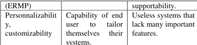
End users have many requirements that should be respected by system designers and developers in order to deliver systems satisfying end users. Based on the work of [20] and [15], we have grouped into four criteria the end users requirements, which are listed in table 1.
Table 1. Criteria of a user-centric solution
Criteria Description Problem of criteria lacking
Functional richness
Features
requested to execute different tasks.
Limited set of offered features.
Usability & intuitiveness
User interfaces, interaction and dialogue mode.
Lack of visibility, feedback,
consistency, non-destructive operations, discoverability, scalability, reliability [23]. Efficiency,
reliability, maintainability and portability
Difficulties that do not refer directly to system features.
Lack of
documentation, performance, security,
(ERMP) supportability.
Personnalizabilit y,
customizability
Capability of end user to tailor themselves their systems.
Useless systems that lack many important features.
Based on this section, we define the user-centric SOA as the expectation of end users, their future hope, and the promise for better information systems. A user-centric SOA offers:
• Empowerment of the end user: Easy and flexible composition on the fly of services by all end users that can design and create new services through the combination and composition of existing services, made possible by reduction of the complexity of services composition techniques.
• Openness of the Information System to the public: the democratization of SOA and the installation of the global SOA. In this context, [26] speaks about the Internet of Services where every user use and access to services.
• More independence of SOA: the adoption of a variety of interoperable technologies in order to meet the great variety of the web.
• Lightweight SOA technologies: the support of SOA technologies by all mobile devices.
2 State of the art
2.1 Mashup frameworks limitations
Mashup is a new paradigm of the Web 2.0 [24] – the new generation of the web - that enables the user generation of services by allowing end users to personalize and customize their applications [13][19][6]. Today, there are a big number of Mashup frameworks on the web, which allow end users to mix visually different heterogeneous resources and thus create new applications called mashups. Mashup frameworks have helped to bridge the gap between end users and software development, but they are still some technical gaps [4]:
sources, which prevent the flexibility of these tools. Thus, existent Mashup tools cannot support the Web Services Mashup and more generally the SOA Mashup. In this context, [25] underline the need of the enablement of Web Services Mashup.
• Mashup frameworks do not allow the creation of business process mashups: the existent Mashup frameworks do not provide ways to design and create complicated use case. In fact, the resources composition and the interaction are based only on the data flow. Moreover, the event-handling concerns only the events from sources and doesn’t satisfy the user interaction level [21].
• Mashup tools do not provide stable applications: [2] asserts that the solutions provided by Mashup tools are fragile, neither stable nor robust.
• Mashup frameworks are still outside the scope of end users: Mashup frameworks still lack simplicity for the end user. In fact, the Mashup tools often use technical concepts like port or wires. For the simple end user, handling these technical concepts is not easy and requires a learning time [22].
These critics show that the Mashup is at an early stage and needs more research. In fact, there is a lack of a powerful language for describing Mashup and realizing advanced Mashup applications. Hence, in order to achieve the user-centric SOA, there is a need to introduce new elements consisting of patterns and models to enhance the development of Mashup applications.
The next section introduces the Enterprise Integration Patterns, and shows their contribution to any integration solution.
2.2 Contribution of the Enterprise Integration
Patterns
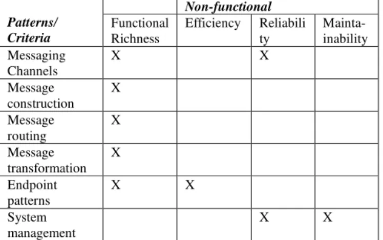
The Enterprise Integration Patterns (EIPs) collected by [12] describe a number of design patterns for enterprise application integration and message oriented middleware. The EIPs are implemented by a set of sophisticated mediation bus, such as Camel, Mule and Apache, in order to achieve very complex integration scenarios. Enterprise Integration Patterns propose the best and common solutions to integration problems. Therefore, when EIPs are used, they enhance the quality of the integrated applications. EIPs consist of six groups of patterns: messaging channels, message construction, message routing, message transformation, messaging endpoints and system management. Based on the book of [12], we categorize these patterns groups according to the four end user satisfaction criteria that we defined and presented in section 1.2.
As it can be seen from table 2, the Enterprise Integration Patterns, when used together, help achieving a high level
of system quality by ensuring four of the end user satisfaction criteria. The use of EIPs is therefore considered as a proof of the system quality. Hence, we had the idea of studying different Mashup frameworks based on the EIPs. The next section gives the result of this study and positions the Mashup frameworks against the user-centric SOA.
Table 2. Categorization of EIPs according to end user SOA criteria
Patterns/ Criteria
Non-functional
Functional Richness
Efficiency Reliabili ty
Mainta-inability Messaging
Channels
X X
Message construction
X
Message routing
X
Message transformation
X
Endpoint patterns
X X
System management
X X
2.3 Study: Mashup frameworks and the user-centric
SOA
As we announced in the previous section, we studied three Mashup frameworks according to the EIPs. The Mashup frameworks considered are: Yahoo! Pipes [27], Jackbe Presto Wires [16] and IBM Mashup Center [14]. As the latter two groups of the EIPs – endpoint and system management patterns - are related to the internal implementation of the solution, we could study the Mashup frameworks only according to the first four groups which are: messaging channels, message construction, message routing and message transformation.
Table 3 shows the number of patterns used among all the existing patterns. The quotient x/y means that x patterns are used among y existing patterns.
Table 3. Study of three Mashup frameworks according to EIPs
Patterns/ Mashup Frameworks
Yahoo! Pipes
Jackbe Presto Wires
IBM Mashup Center
Messaging Channels
3/7 3/7 3/7
Message construction
2/9 2/9 2/9
Message routing 4/12 4/12 3/12 Message
transformation
3/7 4/7 4/7
study showed also that the used patterns are very basic and simple; the three Mashup frameworks fail to implement advanced and sophisticated integration patterns. According to this study and to table 2, we deduced that the three Mashup frameworks fail to totally ensure the criteria of “Functional richness”, “Efficiency”, “Reliability” and “Maintainability”.
We also studied the three Mashup frameworks according to the other end user satisfaction criteria, which are “Usability & intuitiveness” and “Portability”, and the study showed also that they are not completely ensured. Unfortunately we could not introduce this study in this paper because of the restricted number of pages.
All the study that we conducted showed that the Mashup frameworks are not user-centric SOA solutions. To enhance Mashup, we propose the idea of using the EIPs within Mashup frameworks to improve their acceptance by different end users. The next section gives a brief description of our proposed new SOA-Mashuped language based on the Enterprise Integration Patterns.
Table 4. Mashup frameworks and user-centric SOA criteria
UCSOA criteria/Mashup Frameworks
Yahoo! Pipes
Jackbe Presto Wires
IBM Mashup Center
Functional Richness 2 2 2
Personnalizability 3 3 3
Usability & Intuitiveness
2 2 2
Efficiency, Reliability, Maintainability and Portability
3 2 2
3=High, 2=Medium, 1=Low
In this section, we presented and criticized existing Mashup frameworks. Mashup development is still immature and at an early stage and thus needs more research. In particular, there is no significant formalization of Mashup integration. For this reason, we conducted a study of three Mashup frameworks regarding to the end user satisfaction criteria defined in section 1.2. The conclusion drawn from this study led us to the need for new patterns and methodologies to improve Mashup development. The next section is dedicated to the proposal of a new Cloud-based Mashup architecture, that uses a new EIPs-based integration language, while allowing the end user service creation through a new intuitive and self-explanatory creation process. The last requirement – non functional requirement – is out of the scope of this paper.
3 User-centric SOA proposal
3.1 Cloud-Based Architecture
We presented the technical architecture of the user-centric SOA in [5]. This Architecture includes six vertical layers – Web or non Web resources, Resources access, Gadget or Mashup component development, Integration or Mashup components assembly and Visualization or consumption – and two cross layers – Enterprise infrastructure and Web 2.0 collaborative community –. Each layer relies on several services; usability is a very important dimension that should be considered in Gadgets layer, Integration layer and Visualization layer in order to provide end users with intuitive and self-explanatory creation process.
The different services used by Mashup platforms can be homemade (developed internally), or accessible through the Cloud Computing. Indeed, the Cloud Computing can be considered as a novel way to retrieve and use IT-enabled services by customers. The new Software-as-a-Service (SaaS) paradigm allows the supply of services through the internet. According to [7], the Cloud Computing is an emerging paradigm that is based on compute and storage virtualization to deliver reliable services to customers. Customers can access data and applications anywhere in the world on demand.
This way, Mashup platforms can rely on the Cloud Computing services to ensure the operation of each layer of the technical architecture. For example, Enterprise Service Buses could be used for their routing and translation capabilities, BPEL engines could be used for their orchestration capability and the CRUD services offer different services such as identity management, persistent storage, resources access, routing and translation.
Fig. 1 Application architecture of our proposal
3.2 The system point of view: Functional Richness
As it was showed in section 2.2, the Enterprise Integration Patterns help enhancing the system quality in terms of the functional richness. Therefore, our proposal is based on the Enterprise Integration Patterns.
In the following, we give an example of use case to help defining the different entities that will form our language. Our example is taken from the world of physical Mashup. According to [11], physical Mashup is a concept that allows to link and combine real-world objects. So let’s take the example of an end user whose goal is to model and
customize his Mini Cooper car.
The Mini Cooper is considered as an object with features and services. In addition, end users can add various accessories to personalize the car and develop new services. Accessories are considered as objects to be integrated with the car. Examples are integrating the car with an object that displays the temperature, the state of the seatbelt and some advices, with dataflow from central system to the accessory; or integrating the car with a car burglary detector, with an event as a message between the two objects.
To summarize, in order to achieve his task, the end user needs a platform that encapsulates the following elements: • Objects/resources to integrate: Mini Cooper car,
accessories.
• Fields on interface allowing the entry of intermediate data.
• Communication channels that allow binding and forwarding the results between different objects. • Messages of different types which will be carried by
channels and sent by one object to another. A message can be of different types: a message representing a document, a message representing an order, etc.
• Routing components whose role is to route the results of an object to another.
• Translation components that transform the results of an object before sending them to another object. • A view showing a graphical interface that displays the
final result of the integration.
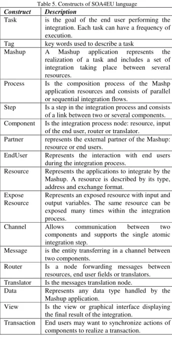
From this simple illustrative example, we have identified the different basic elements that will form our future language that we named SOA4EU (SOA for End User). Table 2 lists these elements.
Table 5. Constructs of SOA4EU language
Construct Description
Task is the goal of the end user performing the integration. Each task can have a frequency of execution.
Tag key words used to describe a task
Mashup A Mashup application represents the realization of a task and includes a set of integration taking place between several resources.
Process Is the composition process of the Mashp application resources and consists of parallel or sequential integration flows.
Step Is a step in the integration process and consists of a link between two or several components. Component Is the integration process node: resource, input
of the end user, router or translator.
Partner represents the external partner of the Mashup: resource or end users.
EndUser Represents the interaction with end users during the integration process.
Resource Represents the applications to integrate by the Mashup. A resource is described by its type, address and exchange format.
Expose Resource
Represents an exposed resource with input and output variables. The same resource can be exposed many times within the integration process.
Channel Allows communication between two components and supports the single atomic integration step.
Message is the entity transferring in a channel between two components.
Router Is a node forwarding messages between resources, end user fields or translators. Translator Is the messages translation node.
Data Represents any data type handled by the Mashup application.
View Is the view or graphical interface displaying the final result of the integration.
Transaction End users may want to synchronize actions of components to realize a transaction.
<Task>::= {<Tag>} {<Frequency>} <Mashup> <Tag>::= [a-zA-Z][0123456789]
<Mashup>::= {<Resource>}+ {<Expose_Resource>}+ {<EndUser>} {<Router>} {<Translator>} <Process> <View>
<Process>::= <Sequence> | <Flow>
<Sequence>:=sequence({<Step>} {<Flow>} {<Step>}) <Flow>::= flow({<Step>} {<Sequence>} {<Step>}) <Step>::= <FromComponant> <ToComponants> <Channel> <Message>
<FromComponant>::= <Componant> <ToComponants>::= {<Componant>}+
<Componant>::= <Partner> | <IntegrationService> <Partner>::= <Expose_Resource> | <EndUSer> <IntegrationService>::= <Router> | <Translator> <EndUser>::= <Input>
<Resource>::= <Type> <DataFormat> <URL>
<Expose_Resource>::= <Resource> <ExpectVariable> <ReturnVariable> {<Transaction>}
<Data>::= <Input> | <Content> | <Event> | <Address> | <Identifier> | <Time> | <Version>| <Key> | <Schema> | <Datatype>
The formalization of “Channel”, “Message”, “Router” and “Translator” elements is done based on the Enterprise Integration patterns that define five patterns for channels, nine patterns for messages, twelve patterns for routers and six patterns for translators.
The next section focuses on the second requirement – usability & intuitiveness – and presents a methodology helping end users to easily compose services.
3.3 The end user point of view: Usability and
Intuitiveness
3.3.1 Goals Composition vs Services Composition
When creating new applications, end users try to achieve a new goal by composing existing sub-goals. Each sub-goal is represented by a service. In this way, when composing services, end users try to resolve a problem whose solution does not exist yet on the web. In fact, the answer exists in the form of many subparts – services – dispersed on the web. Therefore, the inexperienced end user faces many challenges when trying to compose services in response to a new goal:
• Determine the types of resources: what to do? • Find resources that meet the end user criteria (quality,
price, etc.).
• Determine necessary actions for the use of interfaces (selection problems): what and how to use interfaces? • Determine how to arrange and coordinate resources
(integration): how to coordinate the elements? • Determine the final interface of the integrated
resources.
The system has the role of helping end user to answer these different questions, by suggesting resources, providing guidelines for the coordination of resources and providing feedback and documentation for each selected action. Faced with these design problems, the end user will use the knowledge he possesses that describe his goal and which consists of:
• The objective or set of operations that the goal task must accomplish,
• The final result of the goal task (output of the process),
• The frequency of the goal task execution, • The degree of importance of the goal task, • The duration of the goal task.
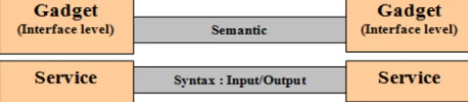
This end-user knowledge represents the semantic which, alone, should be involved in the interaction between the end user and the user-centric SOA platform. Indeed, the service-to-service interaction, which is based on the syntax, is not valid at the interface level. The interface provides gadgets that represent a sub-goal, which is an abstraction of services; therefore, the interaction and communication way at the interface level should also be an abstraction of the communication way between services (Figure 2). Being the abstraction of the syntax, the semantic should be defined as the only way of interaction at the interface level. The semantic is what should be offered to the end user so that he could compose services.
Fig. 2 Interaction way on the service level and the interface level
As the knowledge of the end user is limited to the semantic - goal, output, frequency, importance and duration of the task -, the end user should not and cannot manipulate the syntax. Therefore, the end user knowledge is insufficient to enable the integration of resources and the creation of new applications. The user centric SOA platform has to allow to end users to link the various resources in a very intuitive and self-explanatory way, requiring no knowledge of how to map an output of a resource to an input of another. The interface has then the role of intermediary between the end user and the services and should translate the end user interactions from semantic to syntax or code, as shown in Figure 3.
To achieve this, the user centric SOA platform has to provide the end user with a set of goal prototypes or goals patterns. These goals patterns have the role of guiding the end user through the goals composition process. The next section presents our goals patterns-based suggestion system.
3.3.2 Goals Patterns-Based Suggestion System:
1) What are the goals patterns? In the world of software development, design patterns are solutions or best practices in response to common problems in software design. For example, the "Model-View-Controller" pattern help organizing an application by splitting it into a data model, an interface or a presentation and a controller (control logic, event management and synchronization). Goals patterns represent common and repetitive use cases, and can also be called end users experience patterns. They provide answers to questions like "How to automate the execution of two consecutive tasks - eg. Turn on the light on the entrance of the house and turn on the heating - in response to a triggered event? - ex. presence of a person detected by the sensor.
The following are examples of goals patterns:
• Booking airline ticket, hotel room and car for a destination.
• Purchase order for a product whose quantity reached a limit value.
• Turning on the room light and the coffeemaker when the alarm clock goes off.
While software design patterns are derived from the experience of the software developers, goals patterns are created, improved and enriched by end users themselves. Our objective is to create a relational database of end users goals that end users will feed and develop as they create new applications. This database can also be automatically enriched by systems such as systems for smart homes patterns discovering.
2) Suggestion system: The usefulness of the goals patterns is the suggestion system. In fact, end users will be guided in the process of services composition through the database of goals patterns that contains the possible links between the various gadgets. As gadgets represent sub-goals, the database links represent also relations between sub-goals. The system will utilize this goals patterns database to suggest to the end user links and components in order to build new applications.
The suggestion system should be based on the semantic information, as it is explained in section 3.3.1. In fact, the different links between components should be represented by semantic information as input/output matching. The database of goals patterns being built through the experience of end users, the system will score the various components, depending on the frequency of use, and thus
offer to the end user the best one - which has the highest score.
Our suggestion model is similar to e-mail interfaces - ex. Gmail. When writing a new message, and when the first recipient address is entered by the user, other addresses are proposed and suggested at the basis of the previous messages sent by this user.
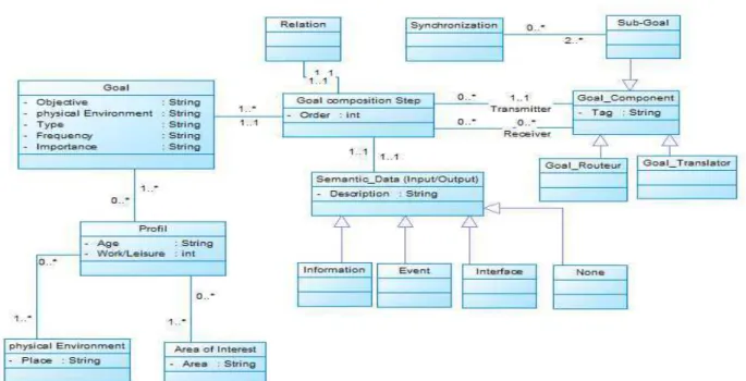
The goals patterns database elements that constitute also the components of the services composition interface are managed by the following description:
• An end-user profile is described by the age, the types of goals (work, leisure or both) the end user is interested in, the areas of interest, the physical environment.
• A profile is a set of goals.
• A goal is described by its type, its physical environment of execution, its objective, its frequency and its degree of importance.
• The realization of a goal involves several composition steps. A step represents a link from a component to one or several components (one-to-one or one-to-many).
• A component can be another application participating in the composition as sub-goal or an operator (translator or router).
• In order to suggest to the end user the appropriate actions, the database must store the various possible relationships between components. Thus, each composition step possesses a relation.
• Each link between two components (composition step) is described by a semantic data that corresponds to the output of the message transmitter and the input of the message receiver.
• The semantic data of a component can be information, event, interface or nothing.
• The participating applications or sub-goals can be synchronized in order to realize a transaction.
The object model of the goals patterns database is represented by Figure 4.
3.4 Linking the end user point of view with the
system point of view
Figure 4.The object model of the goals patterns database
represent solutions to integration problems whose purpose is to achieve a goal.
Table 6 summarize the main elements of correspondence between the two set of elements: the end user point of view elements and the system point of view elements.
Table 6. Correspondences between end user and system points of view
End user point of view element
System point of view element
Goal Mashup
Sub-Goal Service
Relation Channel
Semantic Data Message
Goal Translator Service Translator Goal Router Service Router
Goals Synchronization Services Synchronization (Transaction)
Goal composition Step Service composition Step
The formalization of this correspondence with Backus-Naur Form (BNF) is as follow :
<Goal>::= <Mashup> <Profil> {<Tag>}
<Goal Composition Step> ::= <Service composition Step> <Relation>::= <Canal>
<Semantic data>::= <Message>
<Goal Component>::= <Service Component> <Sub Goal>::= <Partner>
<Goal Router>::= <Service Router> <Goal Translator>::= <Service Translator> <Goal Synchronization>::= <Services Transaction>
4 Illustrative Example
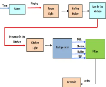
To illustrate our new proposal, we choose an example from the WebOfThings world [10][3] which allows physical objects – called smart objects – to belong to a network and to be linked trough what is called the physical Mashup. Our end user, Alice, wants to schedule a task to be executed every day at 7:00 in the morning - when the alarm goes off. The task, that represents Alice’s goal, consists of turning on the light on the bedroom and the coffee maker in the kitchen. When Alice is in the kitchen, the light must be lit. After Alice had opened the fridge and eaten food, the refrigerator recalculates the food quantities and displays them. If a food quantity reaches a minimum limit, a grocery order is automatically sent (Figure 5).
In the goals patterns database, there is a set of gadgets that Alice could use and that the platform could suggest to her. The gadgets are represented in four sub-directories depending on their output type (information, event, interface, none).
The steps followed by Alice to perform her task are as follows:
input and returns an event presented by ringing. Alice sees on her interface the gadget "Alarm" with the tag "Time" on its left and the red tag "Ring" on its right. At this level, since the output of the "Alarm" gadget is an event, any resource can be added without any constraint on the compatibility of input / output. In fact, an event role is to trigger a sequence of sub-tasks and not to deliver inputs for a sub-task. Thus, the platform does not make any suggestion at this level.
• Alice looks a second time in the sub-directory gathering objects that return nothing (the fourth category) and chooses the "Room Light" object which does not require input data and returns no result. Alice adds the “Room Light” object in sequence to the previous object. Alice also adds – in the same manner – the "Coffee Maker" object in sequence to the previous objects.
• From the event object sub-directory, Alice selects and adds – in sequence – the "I am in the kitchen" object, whose role is to notify the presence of a person in the kitchen.
• Alice adds in sequence the "Kitchen Light" object from the fourth sub-directory (objects that return nothing).
• Alice also adds the "Refrigerator" object which displays the different foods quantities. This object is represented by a gadget with different blue tags on its right representing the amounts of different foods (milk, eggs, cheese, butter, etc). As Alice has already used a filter with the "Refrigerator" object, the platform stored this link in the goals patterns database. At this level and based on the goals patterns database, the platform suggests to Alice, by displaying a button at the top of the window, to add a filter in order to show only foods with a specified limit amount.
• The platform suggests a second time to Alice, based on the goals patterns database, to add the “Grocery" object in order to make purchases for foods with small quantities.
At this level, the role of our end user is finished. In order to be run, Alice’s new application which is made of visual objects and links between these objects should be translated into services and links between these services. Those services links should be built based on the Enterprise Integration patterns presented in section 2.2.
Fig. 5. Illustrative example for our intuitive creation process
The translation of visual objects and links into code (services and EIP links) is the translation of the goals composition – the end user point of view – into the services composition – the system point of view. This translation is realized based on the correspondences already established between the two points of view (section 3.4).
5 Conclusion and future work
References
[1] Allison, H and R. Kelly, R. (1992) ‘The Influence of Individual Differences on Skill in End-User Computing’. Journal of Management Information Systems I Summer 1992, Vol. 9, No. 1, pp. 93-111. (1992).
[2] Anjomshoaa, A., Tjoa, A.M. and Hubmer, A. (2010) ‘Combining and integrating advanced IT-concepts with semantic web technology, Mashup architecture case study’. Paper presented at The 2nd Asian Conference on Intelligent Information and Database Systems, ACIIDS 2010, 24–26 March 2010, pp.13–22, Hue City, Vietnam, Part I, LNAI 5990. (2010).
[3] Avilés-López, E. and García-Macías, J.A. (2009) ‘UbiSOA Dashboard: Integrating the Physical and Digital Domains through Mashups’.Paper presented at The Human Interface and the Management of Information Conference. Designing Information Environments.San Diego, CA, USA, July 19-24, 2009.
[4] Benhaddi, M., Baïna, K. and Abdelwahed, E. (2010) ‘Towards an approach for a user centric SOA’. Paper presented at The third International Conference on Web & Information Technologies, Marrakech, Morocco, April 2010. ISBN: 978-9954-9083-0-3. Pages: 91-104.
[5] Benhaddi, M., Baïna, K. and Abdelwahed, E. (2012) ‘A user centric Mashuped SOA’. Int. Journal of Web Science. Vol. 1, Issue 3. DOI: 10.1504/IJWS.2012.045812
[6] Bradley, A. (2007) Reference Architecture for Enterprise Mashups, Gartner Research.
[7] Buyya, R., Yeo, C. and Venugopal, S. (2008) ‘Market-Oriented Cloud Computing: Vision, Hype, and Reality for Delivering IT Services as Computing Utilities’. Paper presented at The 10th IEEE International Conference on High Performance Computing and Communications (HPCC-08), pages 25{27, Los Alamitos, CA, USA, 2008. IEEE [8] Cypher, A.(1993) Watch What I Do: Programming by
Demonstration. The MIT Press, Cambridge. [9] Gartner. (2005) Gartner Newsroom
http://www.gartner.com/it/page.jsp?id=790717. (2008). (Accessed 10 June 2012).
[10] Guinard, D. and Trifa, V. (2009) ‘Towards the Web of Things: Web Mashups for Embedded Devices’. Paper presented at The 18th Int World Wide Web Conference, April, 2009, Madrid, Spain.
[11] Guinard, D., Trifa, V., Pham, T. and Liechti, O. (2009) ‘Towards Physical Mashups in the Web of Things’. Paper presented at The 6th international conference on Networked sensing systems, INSS'09. 17-19 June 2009. Pittsburgh, PA, USA.
[12] Hohpe, G. and Woolf, B. (2003) Enterprise Integration Patterns: Designing, Building, and Deploying Messaging Solutions, Addison-Wesley Professional.
[13] Hoyer, V., Janner, T., Schroth, C., Delchev, I. and Urmetzer, F. (2009) ‘FAST Platform: A Concept for user-centric, enterprise class Mashups’. Paper presented at The 5th Conference of Professional Knowledge Management, Poster Session, Solothurn, Switzerland, 25-3-2009, pp.5-8. [14] IBM Mashup Center. [Online]
http://www-01.ibm.com/software/info/mashup-center/ (Accessed 04 March 2012).
[15] ISO/IEC 9126-1. (2001) Software engineering – Product quality - Part 1: Quality model. ISO.
[16] Jackbe Presto Wire. [Online]. www.jackbe.com/ (Accessed 04 March 2012).
[17] J. Hierro, J., Janner, T., Lizcano,D., Reyes,M., Schroth,C. and Soriano,J.(2008) ‘Enhancing User-Service Interaction Through a Global User-Centric Approach to SOA’. Paper presented at The Fourth International Conference on Networking and Services IEEE Computer Society, ICNS '08. Washington, DC, USA (2008).
[18] Liu, X., Hui, Y., Sun, W. and Liang, H. (2007) ‘Towards service composition based on Mashup’. Paper presented at The IEEE Congress on Services, 9–13 July 2007, pp.332– 339, Salt Lake City, Utah, USA.
[19] López, J., Pan, A., Bellas, F., and Montoto, P. (2008) ‘Towards a Reference Architecture for Enterprise Mashups’. Paper presented at The Jornadas de Ingeniería del Software y Bases de Datos, 7-10 October 2008. Gijón, Spain.
[20] McCall, J.A., Richards, P.K., and Walters, G.F. (1977) Factors in Software Quality, RADC TR-77-369, 1977, Vols I, II, III, US Rome Air Development Center Reports. Italie. (1977).
[21] Nestler, T. (2008) ‘Towards a Mashup-driven end-user programming of SOA-based applications’. Paper presented at The 10th International Conference on Information
Integration and Web-based Applications & Services, iiWAS 2008, 24–26 November 2008, pp.551–554, Linz, Austria. [22] Nestler, T., Dannecker, L. and Pursche, A. (2009)
‘User-centric composition of service front-ends at the presentation layer’. Paper presented at The 2009 International Conference on Service-oriented Computing, ICSOC/ServiceWave, 24–27 November 2009. Stockholm, Sweden.
[23] Norman, D. and Nielsen, J.. (2010) ‘Gestural Interfaces: A Step Backward In Usability’. Interactions' magazine, Vol. 17 Issue 5, September + October 2010 ACM New York, NY, USA.
[24] O’Reilly, T. (2005). ‘What is Web 2.0 – design patterns and business models for the next generation of software’, O’Reilly [Online] 30 September.
http://www.oreillynet.com/pub/a/oreilly/tim/news/2005/09/3 0/what-is-web-20.html. (Accessed 10 November 2011). [25] Roy, M. (2010) ‘Towards end-user enabled web service
consumption for Mashups. International conference on software engineering’. Paper presented at The 32nd ACM/IEEE International Conference on Software Engineering, ICSE 2010, Vol. 2, pp.413–416, Cape Town, South Africa.
[26] Schroth, C. and Janner, T. (2007) ‘Web 2.0 and SOA: converging concepts enabling the internet of services’. Journal of IT Professional, Vol. 9, No. 3, pp.36–41. (2007). [27] Yahoo! Pipes [Online]. http://pipes.yahoo.com/pipes/.
(Accessed 04 March 2012).