630
MOTORCYCLE CRASH TEST CENTRE: A MOVEABLE BARRIER APPROACH
C.L.Tan1 and S.V.Wong1,2
1
Department of Mechanical & Manufacturing Engineering
Faculty of Engineering, Universiti Putra Malaysia 2
Malaysia Institute of Road Safety Research,
43000 Kajang, Selangor, Malaysia.
E-mail: [email protected]
ABSTRACT
Over recent years, researchers have used full-scale motorcycle crash tests in the field of
road safety research to simulate different types of crash technique and scenario. This
study focuses on the development of laboratory-based motorcycle crash tests. A
moveable barrier, designated as a ‘trolley’ in this study, is designed, developed and
implemented in a laboratory-based motorcycle crash test. The design of the trolley
underwent several versions prior to the final selection. Various design considerations
and factors, such as the trolley’s flexibility in various impact conditions, were weighted.
Finite element analysis and experimental tests examine and explain the details of the
design. The purposeful selection of this trolley is discussed, such as how it might meet
wide industrial market applications. With a laboratory-based crash test facility, various
crash scenarios and motorcycle crashworthiness could be determined in-situ, coupled
with a reduction in expense and time. Therefore, this research would serve to enhance
yet another aspect of automotive engineering.
Keywords: motorcycle, crash test, movable barrier, W-Beam guardrail.
INTRODUCTION
Previously, full-scale motorcycle crash tests have investigated the post-crash injuries of
motorcycle accidents against various barriers, including roadside guardrails and
four-wheeled vehicles. However, full-scale motorcycle crash tests are inefficient in terms of
money and time and are subject to the weather’s grace. Thus, introducing a moveable
barrier, known as ‘trolley’ in this study, not only overcome deficiencies in a full-scale
631
purposeful multi-configuration of the trolley not only suits various crash objectives but
also offers repeatability; a feature necessary to ensure the results is sufficiently free
from bias prior to performing an analysis.
LITERATURE REVIEW
A considerable amount of literature has been published on full-scale motorcycle crash
tests. The trolley developed by TNO Crash Safety Research, is designed in such a way
that it provides forward momentum to the motorcycle through its rear axis with support
at the handlebar (Nieboer et al., 1993). The purpose is to guide the motorcycle and
provide support for the dummy prior to impact, which is similar to the method
developed and used by DEKRA. In this setup, an improvised trolley provided support to
the motorcycle as it slid along a rail at a predetermined speed. The motorcycle was
released prior to impact with the crash object, which in this case was a guardrail (Berg
et al., 2005). In another test by Chawla et al. (2005), the kinetics of crash simulations
are matched with full-scale crash tests that were conducted by the Japan Automobile
Research Institute. A trolley guides the motorcycle at a predetermined speed before it is
released for impact with a passenger car (Chawla et al., 2005). In a similar method,
Ibitoye et al. (2006) developed a jig for a full-scale crash test, in order to validate
simulations on motorcyclist’s kinematics during impact. The jig consisted of rectangular
welded metal frames to guide the motorcycle before it crashed into a W-Beam guardrail
(Ibitoye et al., 2006).
Research has tended to focus on full-scale crash tests rather than on a
laboratory-scale crash tests, especially for two-wheeled vehicles. In existing laboratory-based crash
tests, the sled test is widely used to evaluate four-wheeled vehicle safety systems and
dummy injuries. Fixed and moving barriers were also developed and used in side impact
crash tests on four-wheeled vehicles. Moveable deformable barriers with pole side
impact tests are being used as one of the standard certified tests on passenger cars for
side impact safety analysis (Mizuno et al., 2004; Wang et al., 2006). In addition, a
moving deformable barrier, in accordance with National Highway Traffic Safety
Administration (NHTSA) specifications, was also developed and is widely adopted in
four-wheeled vehicle side impact tests in the United States. In Europe, standard
specifications are adopted in ECE R95 Dynamic Side Impact Regulations. The
wheelbase for the trolley is 3 metres with a total mass of 950 kg (UNECE TD, 1995). It
is important to note that all the moveable barriers that have been developed so far, are
only suitable for four-wheeled vehicles and not for motorcycle crash tests. However,
632
commissioned for four-wheeled vehicle crash tests, some could be improvised for
laboratory-based motorcycle crash tests.
METHODOLOGY AND DESIGN CONSIDERATION
Prior to the actual design of the trolley, a few draft versions were drawn and these drafts
studied and improved. At this early stage, all design factors and test considerations have
to be incorporated. Finite element analysis (FEA) is then used to further determine the
actual representation of the trolley’s attachment, especially the W-beam guardrail. This
is important as it represents the actual soil-planted C-post at the roadside, which is
1.12 metres deep (MPW, 1993). Once the design of the trolley was finalised, it was
fabricated and underwent a few trial runs, validating its travelling velocity, before it was
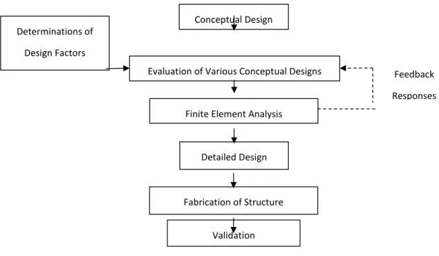
implemented in actual motorcycle crash tests. Figure 1 below shows the design flow
chart.
Figure 1. Design flow chart.
A few design factors should be considered prior to setting up a laboratory-based
motorcycle crash test facility, which includes essential requirements and constraints. In
addition, it must be able to simulate a full crash scenario and perform dynamic testing,
something which is not possible with the conventional sled test. The motorcycle must be
free to steer after release from the guidance system with the front wheel aligned straight
in the direction of the crash. The facility should also able to accommodate dummy
Feedback
Responses Conceptual Design
Evaluation of Various Conceptual Designs
Detailed Design Finite Element Analysis
Fabrication of Structure
Validation Determinations of
633
testing for investigative purposes of post-crash dummy kinematics. The barrier, a
front-loaded detachable fixture, should offer flexibility in material fixture as well as crash
objects. It may also allow consideration of frontal or angled impacts. These options
facilitate the most important factor, which is repeatability.
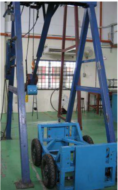
Wong et al. (2006) developed a patented machine known as the MechTTM Impactor, which is capable of undertaking various impact configurations. With the
MechTTM Impactor, kinetic energy is transferred to the crash object via the trolley. Figure 2 shows the trolley placed in the MechTTM Impactor prior to impact.
Figure 2. Trolley and MechT impactor.
FABRICATION AND ANALYSIS
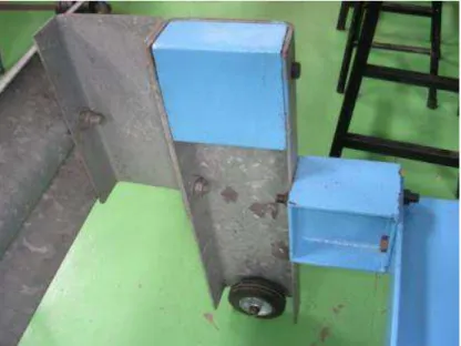
The dimension for a generic trolley is at 1325 mm long, 1000 mm wide and 600 mm in
height. An attachable barrier is also incorporated to enable flexibility in material fixture
for each selective crash test. The body structure is developed from 25.4 × 25.4 mm square
bars that are welded together to form rectangular frames, to which four wheels are then
fixed, as shown in Error! Reference source not found.3. The top of the trolley is equipped
with a removable steel fencing mesh for safety considerations. This barrier-exchangeable
feature enables either a solid metal plate, which acts as a ‘rigid wall’ or W-beam
guardrail, or deformable honeycomb structures, which act as ‘passenger car bumper
W-634
beam guardrail attached at the front acting as the crash barrier, the trolley with barrier
would be 2085 mm long and 1960 mm wide.
Figure 3. Trolley with four wheels.
To determine the structural integrity on the trolley, a simple FEA was performed
with a front attachment of C-posts of a W-beam guardrail in place. In an actual scenario,
long C-posts are planted deep into the ground alongside highways. In this setup,
attaching the long C-post onto the trolley, results in reduced lateral strength due to the
free end fitting arrangement. During an impact, translational and rotational deformation
is observed along the C-post. Based on FEA, it was determined that a rigid block with
similar width but height of 162 mm needed to be added to the upper portion of the long
C-post, as shown in Error! Reference source not found.4.
635
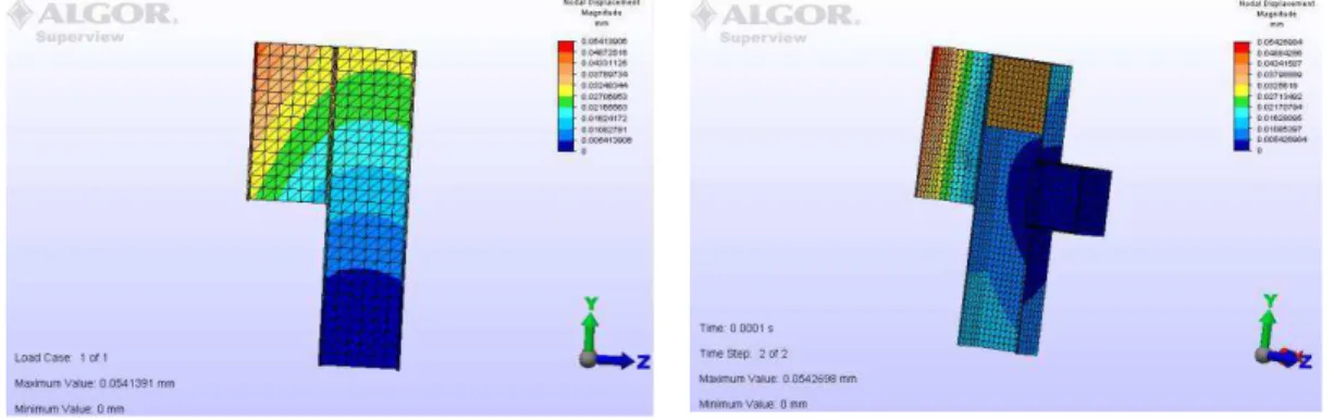
The modified structure, re-analysed via FEA, revealed that the stress is still well
within the elastic region but with a maximum difference in deformation between the two
C-posts of less than 0.00017 mm. This provides a high correlation between the trolley’s
C-post versus the soil planted C-post. The results are shown in Error! Reference source
not found.5 and full views of the W-beam guardrails are shown in Error! Reference
source not found.6.
(a) (b)
Figure 5. (a) Deformation on soil planted C-Post (b) Deformation on trolley’s C-Post
fitted with rigid block
(a) (b)
Figure 6. (a): Actual Soil Planted W-beam Guardrail Deformation; (b): Trolley’s W
-beam Guardrail Deformation Fitted with Rigid Block
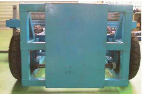
The trolley is also designed with a rear solid metal back plate, as shown in
Figure 7: Back plate7. The purpose of the rear-affixed plate is to provide a
counter impact zone from the pendulum that in effect will project the whole trolley
forward; hence, providing a moveable barrier while the weight of the solid metal plate
636
in mind, this trolley is designed to accommodate various load configurations. There are
two adjustable height bars at the front and back of the movable barrier, as shown in
Figure 8. Loads or specially designed weights can be hooked horizontally either to the
front or back of the trolley depending on crash test requirements. Different weights
added along the structure may shift the centre gravity of the trolley and this feature
could be exploited further in future studies. The height of the bars can be adjusted
depending on impact configurations. This trolley with an attachable barrier is designed
not only for ease of operation and maintenance but also for the ability for customisable
impact conditions with flexibility in varying the impact loads.
637
Figure 8: Adjustable height bar for extra load requirement.
CONCLUSIONS
The moveable barrier provides adaptability for a wide range of use. It can act as a
replacement for laboratory-level full-scale motorcycle crash tests. It can also be
instituted as a test standard for motorcycle design approval. Through laboratory-based
motorcycle crash tests, various design factors and motorcycle crashworthiness could be
determined, with reduced costs and most importantly, independent of the weather.
Motorcycle manufacturers would be able to use the facility to improve in-house
motorcycle parts or complete structural designs. In accident reconstructions, the facility
would greatly contribute to assessing accident impact velocity via its flexible crash
configuration settings.
REFERENCES
Berg, F.A., Rucker, P., Gertner, M., Konig., J., Grzebieta, R. and Zou, R. 2005.
Motorcycle impact into roadside barriers – real-world accident studies, crash
tests and simulations carried out in Germany and Australia. Proceedings of
International Conference on Experimental Safety Vehicles, Munich, Germany,
pp. 1-12.
Chawla, A., Mukherjee, S., Mohan, D., Bose, D., Rawat, P., Nakatani, T. and Sakurai,
M. 2005. FE simulations of motorcycle-car frontal crashes, validation and
observations. International Journal of Crashworthiness, 10(4): 319-326.
Ibitoye, A.B., Hamouda, A.M.S., Wong, S.V. and Radin, R.S. 2006. Simulation of
motorcyclist’s kinematics during Impact with W-beam guardrail. Advances in
Engineering Software, 37: 56-61.
Mizuno, K., Arai, Y. and Newland, C.A. 2004. Compartment Strength and its
evaluation in car crashes. International Journal of Crashworthiness, 9(5):
547-557.
MPW (Malaysia Public Works) - Jabatan Kerja Raya (JKR) 1993. Manual on design
guidelines of longitudinal traffic barrier arahan teknik (Jalan) 1/85.
Nieboer, J.J., Wismans, J., Versmissen, A.C.M., van Slagmaat, M.T.P., Kurawaki, I.
and Ohara, N. 1993. Motorcycle crash test modelling. Proceedings of 37th Stapp Car Crash Conference, San Antonio, CA, USA, pp. 273-288.
UNECE TD (United Nations Economic Commission of Europe, Transport Division).
1995. Vehicle regulations added to the 1958 agreement (Regs 81-100)
Concerning the adoption of uniform conditions of approval and reciprocal
638
95, Uniform provisions concerning the approval of vehicles with regard to the
protection of the occupants in the event of a lateral collision, p. 37.
Wang, D., Dong, G., Zhang, J. and Huang, S. 2006. Car side structure crashworthiness
in pole and moving deformable barrier aside impacts. TsingHua Science and
Technology, 11(6): 725-730.
Wong, S.V., Hamouda, A.M.S., Megat Ahmad, M.M., Radin Umar, R.S., Tan, K.S.
2006. MechT 524 CI-75 with capacity of 25J, 50J and 75J, United State Patent
2004103713.