Faculdade de Engenharia da Universidade do Porto
A Wearable High-Accuracy Hand Sensing System
Diogo Alexandre Mendes da Costa
Dissertação realizada no âmbito do
Mestrado Integrado em Bioengenharia
Major Engenharia Biomédica
Supervisor: João Paulo Trigueiros da Silva Cunha
Collaborator: Duarte Filipe Dias
Collaborator: Nuno Ferreira
September 17, 2018
ii
iii
Resumo
As limitações na força e na cinemática da mão e do pulso podem debilitar drasticamente um individuo com impacto direto no seu bem-estar, impedindo-o de realizar eficientemente as suas atividades diárias. Estes casos estão geralmente relacionados com patologias como artrite, AVC, doença de Parkinson, entre outras. Na prática clínica são utilizados dispositivos convencionais combinados com metodologias simples de forma a realizar uma avaliação esporádica e intervir na apreciação da reabilitação. De modo geral, estes dispositivos têm como principais objetivos a medição dos ângulos máximos de cada articulação e a força em algumas posições de interesse, no entanto estes começam a tornar-se obsoletos. Assim, é de extrema importância o desenvolvimento de dispositivos tecnológicos que auxiliem o diagnóstico destas limitações através de parâmetros objetivos.
Esta dissertação tem como objetivo desenvolver um novo protótipo de um dispositivo vestível (baseado em tecnologia IMUs) acompanhado de uma plataforma de visualização e processamento, para medir a amplitude máxima nos diferentes movimentos do pulso. A este trabalho foi ainda incorporado o algoritmo de quantificação de rigidez já implementado. Trabalho este desenvolvido ao abrigo do projeto BioGlove no INESC TEC em parceria com a Biodevices S.A., incluindo ainda o projecto iHandU do INESC TEC.
Assim, a primeira fase de implementação consistiu na integração do hardware e no desenvolvimento do firmware para aquisição dos dados inerciais, calibração dos sensores e envio dos dados através do Bluetooth de baixa energia para a aplicação Android. A segunda fase compreendeu um estudo para a otimização do algoritmo de estimação da orientação baseada nos dados dos IMUs, a implementar posteriormente na aplicação Android. Na terceira fase, assumindo um papel central no sistema, foi desenvolvida uma aplicação Android para receber os dados do protótipo, realizar a avaliação e comunicar com a base de dados onde as avaliações são guardadas. Por fim, a quarta e última fase contemplou o desenvolvimento de uma plataforma web para visualização das avaliações e gestão da base de dados, com o objetivo de produzir um sistema completo e de arquitetura escalável. De uma visão global, os médicos que utilizem este sistema podem realizar a avaliação de forma simples, intuitiva e tecnológica, disponibilizando as avaliações em qualquer dispositivo.
No final, o protótipo desenvolvido como prova de conceito comprova a possibilidade de avaliar parâmetros cinemáticos do pulso a partir de sensores inerciais com precisão, encontrando-se preparado para a próxima integração. Desta forma, o trabalho desenvolvido contribui com mais uma parcela para o avanço dos dispositivos vestíveis na área de diagnóstico médico assistido.
v
Abstract
The limitation of strength and kinematics in hand and wrist can drastically debilitate the well-being of an individual, preventing him from achieving the daily activities effectively. These cases are usually related to pathologies such as arthritis, stroke, Parkinson's disease, among others. In clinical practice, conventional devices combined with simple methodologies are used to perform a sporadic assessment and intervene during rehabilitation. In general, these devices aim to measure the maximum angles of each joint and the strength in some positions of interest. However, they are becoming obsolete. Thus, it is imperative to develop technological devices to assist in the evaluation of these limitations through objective parameters.
This dissertation aims to develop a new prototype of a wearable device (based on IMUs technology) combined with a visualization and processing platform to measure the range of motion in the wrist. To this work was incorporated the quantification of the rigidity algorithm already implemented. This work was developed under the BioGlove project at INESC TEC in partnership with Biodevices S.A., being included the iHandU project of INESC TEC.
Thus, the first phase of implementation consisted in the hardware integration and firmware development for inertial data acquisition, sensors calibration, and data transmission via Bluetooth Low-Energy to an Android application. The second phase comprised a study for the optimization of the orientation’s estimation algorithm based on IMUs data to be implemented in the Android application. In the third phase, assuming a central role in the system, an Android application was developed to receive the data from the prototype, perform the evaluation and communicate with the database where the evaluations are saved. Finally, the fourth and final phase included the development of a web platform for visualization of evaluations and database management, with the aim of producing a complete and scalable architecture of the system. The physicians who use this system can carry out the evaluation in a simple, intuitive and technological way, making the evaluations available on any device.
In the end, the developed prototype as a proof of concept proves the possibility of accurately assessing the kinematic parameters of the wrist using inertial sensors, being prepared for the next iteration. The Android application and the web platform complete a system with a more significant number of functionalities, allowing the evaluation to be made and conclusions to be drawn in a simple, intuitive and technological way. Thus, the work developed contributes to another portion for the advancement of wearable devices in assisted medical diagnosis.
vi
vii
Agradecimentos
Em primeiro lugar gostaria de agradecer à minha família, principalmente aos meus pais e aos meus avós por me proporcionarem a oportunidade e o caminho até esta nova fase que se avizinha. Gostaria ainda de agradecer a todas as pessoas que sempre me acompanharam durante todo o percurso, e que proporcionaram grandes momentos e grandes lembranças. Momentos estes que espero que no futuro continuem a ser tão bons ou melhores como os aconteceram até aqui.
Relativamente a esta dissertação, em primeiro lugar gostaria de agradecer ao Professor Doutor João Paulo Cunha pela oportunidade de realizar este trabalho, sempre com a vertente de futura aplicabilidade em soluções reais, tornando-se mais do que um vulgar projeto. Gostaria também de agradecer a sua partilha de conhecimento para que o trabalho cumprisse da melhor forma os requisitos. Quero ainda deixar uma palavra de apreço a todos os membros do BRAIN Lab, principalmente ao Duarte Dias por toda a orientação e total disponibilidade para discutir decisões, possíveis soluções e aprimoramentos do trabalho. Por último, gostaria de agradecer a disponibilidade de todas as pessoas que deram o seu contributo para esta dissertação.
ix
Contents
Chapter 1: Introduction ... 1
1.1 - Background and Context ... 1
1.2 - Motivation ... 2
1.3 - Objectives ... 2
1.4 - Document Outline ... 3
Chapter 2: State of Art ... 5
2.1 - Hand Anatomy ... 5
2.1.1 - Bones and Joints ... 5
2.1.2 - Ligaments and Other Supporting Structures ... 7
2.1.3 - Muscles ... 8
2.2 - Hand Kinematics ... 10
2.2.1 - Metrics and Parameters Evaluated ... 10
2.2.2 - Associated Pathologies ... 14
2.2.2.1 - Arthritis ... 14
2.2.2.2 - Traumatic Brain Injury (TBI) ... 15
2.2.2.3 - Stroke ... 15
2.2.2.4 - Parkinson’s Disease (PD) ... 15
2.2.2.5 - Systemic sclerosis (SSc) ... 16
2.2.2.6 - Spinal Cord Injury (SCI) ... 16
2.2.2.7 - Illnesses with side effects on hand ... 16
2.2.2.8 - Work-related ... 16
2.2.3 -Common Devices in Medicine ... 17
2.2.4 -Alternative Devices on the Market or being Developed ... 18
2.2.4.1 - Datagloves based on flexible optical sensors ... 18
2.2.4.2 - Datagloves based on flex sensors ... 19
2.2.4.3 - Datagloves based on inertial tracking ... 21
2.2.4.4 - Magnetic Tracking ... 22
2.2.4.5 - Optical Tracking ... 23
2.3 - Project Fundamentals ... 25
2.3.1 -Wearable Systems ... 25
2.3.1.1 - Generic System Architecture ... 25
2.3.1.2 - Market Opportunity ... 28
2.3.2 -Inertial Measurement Unit (Working Principles) ... 28
2.3.2.1 - MEMS accelerometers ... 29
2.3.2.2 - MEMS gyroscopes ... 30
2.3.2.3 - MEMS magnetometers ... 31
x
2.3.4 -Representation of Orientation ... 34
2.3.5 -Estimation of Orientation ... 36
2.3.5.1- Kalman Filters... 37
2.3.5.2- Complementary Filters ... 37
Chapter 3: A Wearable Hand Sensing System ... 43
3.1 - System Architecture ... 43
3.2 - Hardware Integration ... 44
3.2.1- Inertial Measurement Unit ... 44
3.2.2- Arduino Pro Mini ... 46
3.2.3- Bluetooth Low-Energy ... 47
3.2.4-Wearable Device Developed ... 48
3.3 - Firmware ... 49
3.3.1- Communication Protocols ... 49
3.3.1.1 - I2C Communication Protocol ... 50
3.3.1.2 - Universal Asynchronous Receiver/Transmitter (UART) interface ... 51
3.3.1.3 - Generic Attribute Profile (GATT) ... 51
3.3.2- Firmware Developed ... 53
3.3.2.1- Initialization ... 54
3.3.2.2- Loop ... 55
3.4 - Sensor Fusion Algorithm ... 57
3.5 - Android Application ... 64
3.5.1- Welcome Interface ... 65
3.5.2- Main Menu ... 66
3.5.3- Evaluation Interface ... 66
3.5.3.1- Flexion/Extension Evaluation ... 70
3.5.3.2- Radial/Ulnar Deviation Evaluation ... 73
3.5.3.3- Wrist Rigidity Improvement Evaluation ... 75
3.5.4- Wearable Device Calibration ... 78
3.5.5- Preferences ... 79
3.5.6- Synchronize Stored Data with Online Database ... 80
3.6 - Web Platform ... 82
3.6.1– Database Structure ... 83
3.6.2- Website Interface Design ... 84
3.6.2.1- Sign In Interface... 84
3.6.2.2- User Interface ... 87
3.6.2.3- Administrator Interface ... 88
3.7- Wearable System ... 91
Chapter 4: Prototype Performance Evaluation ... 93
4.1- Range of Motion ... 93
4.2- Rigidity Quantification ... 96
Chapter 5: Conclusion and Future Work ... 97
xi
List of Figures
Figure 2.1- Joints and bones of the fingers and wrist. Denomination and location of bones and joints of the fingers in A (anterior view) and of the left wrist in B (anterior view) [6]. ... 6 Figure 2.2 - Hand and wrist ligaments. In this figure it can be observed the ligaments of
phalangeal and metacarpal region in A (posterior view), and the proximal region ligaments in B (anterior view), C (posterior view) and D (posterior view). The wrist ligaments wrist ligaments are illustrated in E (anterior view) and F (posterior view), both on the left wrist [6, 14]. ... 8 Figure 2.3 - Hand muscles. Anterior view in A and posterior view in B [6]. ... 9 Figure 2.4 - Wrist muscles. Anterior view in A and posterior view in B [6]. ... 10 Figure 2.5 - Main movements of the MCP joint. The movement of flexion/extension in A
and abduction/adduction in B [5]. ... 12 Figure 2.6 - Main movements of the thumb. The movement of abduction/adduction in A,
flexion/extension in B and opposition/reposition in C [5]. ... 12 Figure 2.7 - Main movements of the Wrist. The movement of pronation/supination in A,
flexion/extension in B and radial/ulnar deviation in C [5]. ... 13 Figure 2.8 - Main pinch movements. In this figure are illustrated lateral pinch in A,
tip-to-tip pinch in B and three-fingered pinch in C [5]. ... 14 Figure 2.9 - Goniometers and pollexograph. In this figure are illustrated the traditional
goniometer in A, the electrogoniometer in B and pollexograph in C [47–49]. ... 17 Figure 2.10 - Pinchmeter and Jamar dynamometer. In this figure are illustrated the
pinchmeter in A, the Jamar dynamometer in B [50, 51]... 18 Figure 2.11 - Datagloves based on flexible optical sensors. In this figure are illustrated the
Sayre Glove in A and the 5DT Data Glove 14 Utra in B [55, 58]. ... 19 Figure 2.12 - Datagloves based on flexible flex sensors (I). In this figure are illustrated the
Power Glove in A, the CyberGLove III in B and Manus VR glove in C [64, 66, 67]. ... 20 Figure 2.13 - Datagloves based on flexible flex sensors (II). In this figure is illustrated the
xii
Figure 2.14 - Datagloves based on inertial tracking. In this figure are illustrated the IGS Cobra Glove from Synertial with the respective sensors location in A and Synertial's
Calibration Pipeline in B [73, 74]. ... 21
Figure 2.15 - Datagloves based on inertial tracking under development. In this figure are illustrated the PowerGlove in A, the IMU Smart Glove in B and the dataglove proposed by Pei-Chi Hsiao et al. in C [72, 76, 77]. ... 22
Figure 2.16 - Magnetic tracking sensors. In this figure can be seen the Polhemus sensors [84]. ... 23
Figure 2.17 - 3D hand tracking software developed by CVRL, ICS and FORTH. In this figure can be seen the output model [80]. ... 23
Figure 2.18 - ART active finger tracking device. In this figure is illustrated the 5 fingers version [82]. ... 24
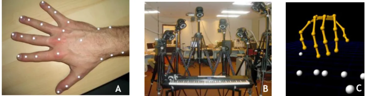
Figure 2.19 - Example of a Vicon passive motion capture system. The figure illustrates a study carried out by MDW (University of Music and Performing Arts Vienna), where the passive markers are found in A, the configuration of infrared cameras in B and the respective output in C [85]. ... 24
Figure 2.20 - Generic System Architecture for WHMS. Adapted from [89]. ... 26
Figure 2.21 - Schematic of MEMS accelerometers. The figure illustrates the capacitive-based accelerometer in A, the piezoelectric-capacitive-based accelerometer in B and piezorestive-based accelerometer in C. Adapted from [109]. ... 30
Figure 2.22 - Schematic of MEMS gyroscopes. The figure illustrates the turning fork gyroscope in A and the linear vibrating plate gyroscope in B. Adapted from [105, 110]. ... 31
Figure 2.23 - Schematic of MEMS magnetometers. The figure illustrates Hall effect based MEMS magnetometer in A, the GMR magnetometer in B, the AMR magnetometer in C, the MTJ magnetometer in D, and Lorentz force magnetometers in E. Adapted from [111, 115]. ... 32
Figure 2.24 - Illustration of the earth frame (e-frame), inertial frame (i-frame) and navigation frame (n-frame). This figure illustrates the three frames external to the device and their relations [107]. ... 33
Figure 2.25 – NED coordinate system [117]... 33
Figure 2.26 - Schematization of Tait-Bryan angles. This figure shows the rotation of the yaw around the z-axis in A, the rotation of the pitch around the y-axis in B, and the rotation of the roll around the x-axis in C [107]. ... 34
Figure 2.27 - Tait-Bryan angles (practical case) [121]. ... 35
Figure 2.28 - Schematic illustration of dead-reckoning. This scheme illustrates the common process for obtaining the position and orientation of the data coming from the accelerometer and gyroscope [107]. ... 36
Figure 2.29 - Madgwick and Mahony Filter schematics. ... 42
Figure 3.1- Architecture Implemented. ... 43
xiii
Figure 3.3 - Inertial Measurement Unit MPU-9250 [131]. ... 44
Figure 3.4- IMU MPU9250 schematic [135]. ... 45
Figure 3.5 - Internal block diagram of MPU9250 [135]. ... 46
Figure 3.6 - Arduino Pro Mini and FTDI Basic Breakout. The figure illustrates the Arduino Pro Mini in A, the FTDI Basic Breakout in B and the connection between them in C [136, 137]. ... 47
Figure 3.7 - RN4871 Bluetooth module. The figure illustrates the RN4871 in A, and the breakout made by BRAIN Lab [140]. ... 47
Figure 3.8 - Full diagram circuit. This figure shows from right to left the following components: battery, Arduino Pro Mini, RN4871 Bluetooth module and both MPU-9250 IMUs. ... 48
Figure 3.9 – Final Prototype. ... 49
Figure 3.10- Large Overview of the wearable device. ... 49
Figure 3.11- Message frame on 𝐼2𝐶 [142]. ... 50
Figure 3.12- Serial packet architecture [143]. ... 51
Figure 3.13- Data exchange process between a peripheral (the GATT Server) and a central device (the GATT Client) [144]. ... 52
Figure 3.14 - High-level architecture of GATT transactions [144]. ... 52
Figure 3.15- Activity diagram of the firmware developed. ... 53
Figure 3.16 - IMUs placed in the Bosch sensor (model PAM 220). ... 57
Figure 3.17 - Offline Algorithm Activity Diagram. ... 58
Figure 3.18 - Output of the acquired datasets for Madgwick Filter with β of 0.106. ... 59
Figure 3.19 - RMSE as a function of β for the original output of the Madgwick filter and after the moving average filter. ... 59
Figure 3.20 - RMSE as a function of Ki and Kp for the original output of the Mahony filter. ... 60
Figure 3.21- RMSE as a function of Ki and Kp for the original output of the Mahony filter after the moving average filter. ... 60
Figure 3.22 - Relation between the several RMSE values for a given β. ... 61
Figure 3.23- Estimated/measured angles vs. ground truth for roll, pitch and yaw. ... 61
Figure 3.24- Bland-Altman Plots for roll, pitch and yaw. ... 62
Figure 3.25- RMSE analysis for each step. ... 63
Figure 3.26- Bland-Altman Plots for roll, pitch and yaw in each step. ... 64
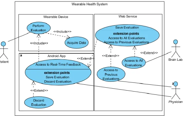
Figure 3.27- Use cases diagram of the Android application. ... 65
xiv
Figure 3.29 - Main menu interface. ... 66
Figure 3.30 - Interface to select the Bluetooth device to connect. The figure represents the selection interface in A, and the request to connect the Bluetooth in B. ... 67
Figure 3.31 – Evaluation Interface. The figure represents the main interface in A, and the connection failure notification in B. ... 67
Figure 3.32- Evaluation Information Dialog. ... 68
Figure 3.33 – Interface with active evaluation. ... 69
Figure 3.34 - Tait-Bryan angles vs range of motion. ... 70
Figure 3.35- Ideal flexion/extension position used in clinical evaluation [157]. ... 71
Figure 3.36- Ideal pronation/supination position [158]. ... 72
Figure 3.37- Ideal radial/ulnar deviation position used in clinical evaluation [157]. ... 74
Figure 3.38- Physician method to assess wrist rigidity [159]. ... 75
Figure 3.39- Final dialog interface. ... 77
Figure 3.40 - Calibration Interfaces. The figure represents the selection interface in A, and the main calibration interface in B. ... 78
Figure 3.41- Interfaces of the calibration process. ... 79
Figure 3.42- Preferences Interface. ... 79
Figure 3.43- Sign In interface... 81
Figure 3.44- Evaluation management interface. ... 81
Figure 3.45- UML Use Cases of the developed web platform. ... 83
Figure 3.46- Entity-relationship model of the database. ... 83
Figure 3.47- Sign in interface ... 84
Figure 3.48- Account Control Messages. ... 85
Figure 3.49- Message to recover the password. ... 85
Figure 3.50- Create Account interface. ... 86
Figure 3.51- Create Account Messages. ... 86
Figure 3.52- User interface. ... 87
Figure 3.53- Change Password interface. ... 88
Figure 3.54- Invalid password message. ... 88
Figure 3.55- Admin interface (evaluations table). ... 89
xv
Figure 3.57- Final Prototype. ... 91 Figure 4.1- Goniometer similar to the one used in this work [160]. ... 93 Figure 4.2- Positions for evaluation of flexion in A and extension in B [162]. ... 94 Figure 4.3- Positions for evaluation of radial deviation in A and ulnar deviation in B [162]. .. 95 Figure 4.4- Prototype tested during surgery. ... 96
xvii
List of Tables
Table 2.1 - Prime ligaments of the hand-wrist complex [6, 11]. ... 7
Table 2.2 - Prime movers of the hand [6]. ... 9
Table 2.3 - Prime movers of the wrist [6]. ... 10
Table 3.1- Characteristic Properties [145] ... 53
Table 3.2- Results obtained by the Sensor Fusion Algorithms. ... 60
Table 4.1- Measurements obtained in flexion. ... 94
Table 4.2- Measurements obtained in extension. ... 94
Table 4.3- Measurements obtained in radial deviation. ... 95
xix
Abbreviations and Symbols
List of abbreviations (alphabetical order)
ADC Analog-to-Digital Converter CMC Carpometacarpal joint DCM Direction Cosine Matrix DIP Distal interphalangeal joint
DoF Degree of Freedom
DPM Digital Motion Processor™ ECF Explicit Complementary Filter GATT Generic Attribute Profile
GDCF Gradient Descent Based Complementart Filter IMU Inertial Measurement Unit
I2C Inter-Integrated Circuit
IC Integrated Circuit
IDE Integrated Development Environment IoT Internet of Things
IT Information Technology IP Interphalangeal joint
MARG Magnetic, Angular Rate and Gravity Module MCP Metacarpophalangeal joint
MEMS Micro Electrical Mechanical Systems
OA Osteoarthritis
PD Parkinson´s Disease
PHS Personal Health Systems PIP Proximal interphalangeal joint RA Rheumatoid arthritis
ROM Range of Motion
SCI Spinal Cord Injury
xx SSc Systemic sclerosis
SWS Smart Wearable Systems TBI Traumatic Brain Injury
UART Universal Asynchronous Receiver-Transmitter
UI User Interface
UML Unified Modeling Language UUID Universally Unique Identifier WHS Wearable Health Systems
WMSD Work-related musculoskeletal disorders XML Extensible Markup Language
List of symbols ω Angular velocity ψ Yaw/heading θ Pitch Φ Roll
Chapter 1
Introduction
1.1 - Background and Context
The hand and wrist allow a wide range of tasks, from the simplest to the most complex. These have always been important to the human being, inferring the ability to build and communicate, and allowing him to create our current society [1, 2].
The limitations in kinematics and strength of these structures come from a variety of pathologies such as arthritis, stroke, Parkinson's disease and many others with less prevalence in the population. Additionally, the hand-wrist complex is a fundamental and active part of the human body, becoming vulnerable to work-related pathologies. These injuries, in more severe cases can lead to disability, impairing the performance of the individual on daily tasks and at the workplace [3].
At the moment there are already some devices in the clinical environment capable of objectively evaluate kinematics and strength limitations of the hand and wrist, which are combined with the help of questionnaires and professional experience [4]. These devices measure the maximum angles made by one joint at a time and the strength in some specific cases, usually related to grasp and pinch movements [5]. As a result, this methodology presents an unfeasible process regarding time efficiency and costs associated with the duration of the exam. From a more technological point of view, there are already devices in the market that have the potential to have a positive impact in such areas. Nevertheless, these have been specially developed with the intention of being used in animation and virtual reality. Given the lack of such a tool in the clinical environment, there is a need to create an easy-to-use device, taking advantage of the recent exponential technological growth of mobile devices and wearable health systems.
The work developed in this dissertation is based on the BioGlove and iHandU projects developed by the Biomedical Research And INnovation (BRAIN) group hosted in INESC TEC, and supervised by Professor Ph.D. João Paulo Cunha. This work is intended to improve the BioGlove project through a prototype as a proof of concept with new sensors to measure the maximum angles in the wrist, incorporating the innovation and leading development in the quantification of the motor improvements during the Deep Brain Stimulation (DBS) surgeries in charge of the iHandU project.
2 Introduction
1.2 - Motivation
The lack of technological devices for this type of assessments gives to biomedical engineering an opportunity to improve the current systems regarding accuracy and time efficiency. This work integrates the relatively recent concepts of mobile devices and wearable health systems. Currently, these are two of the most promising concepts in medical technology. The choice of these concepts focuses on increasing knowledge in an emerging area with countless market opportunities in the near future, with the aim of improving the technology in the current clinical diagnoses. Throughout the work, the possibility of working in distinct areas with different programming languages allowed me to carry out an end-to-end project, making my knowledge more widespread.
In addition to this perspective, the opportunity to work on projects of INESC TEC in partnership with Biodevices, S.A. with the mentality to improve and develop new products that can be released in the market is a great incentive and enormous personal gratification.
1.3 - Objectives
In this dissertation, different areas and steps need to be covered to understand and implement a technological project in hand/wrist kinematics, with the primary goal of future application in the clinical environment. Consequently, this dissertation is segmented into 5 main objectives.
The first objective is to understand the complex working principle of hand and wrist, how the kinematic evaluation is performed by physicians and what parameters should be analyzed. Then, a study of the technological devices (on the market or being developed) with relevant features for this dissertation becomes crucial. From the technical point of view, it is still essential to build background knowledge in wearable health systems, especially their generic architecture and their standard operating principles. In addition to wearable health systems, it is necessary to acknowledge the operating principals of inertial measurement units and their differences, emphasizing the theoretical insight that makes these sensors a viable option for this project.
The second objective is to develop a glove prototype with the necessary hardware and firmware to acquire, process and send kinematic data via Bluetooth Low-Energy to the Android smartphone. This prototype will act as proof of concept for a new stage of the BRAIN group projects.
The third objective is to perform an offline processing from the data sent by the wearable device in order to understand the best algorithm to estimate the angles performed by the patient.
The fourth objective is to develop a simple and intuitive Android application to receive, process and illustrate the real-time kinematics evaluation of the patient's wrist from the data received by BLE. This application should have a central role in the system, allowing the storage of the performed evaluation and their upload to an online platform, providing a more user-friendly, structured, efficient and technological methodology to the health professional. The fifth and final objective contemplates the development of a web platform consisted by a database and a website. This allows a greater management of the evaluation, extending the scalability of the project.
Document Outline 3
1.4 - Document Outline
This master thesis is divided into 5 chapters. After this introductory chapter, four other chapters contemplate all the state of the art necessary for the accomplishment of this dissertation, the prototype development process, the results obtained by comparison with devices currently used in the clinical environment, and finally the main conclusions and future work.
Having that said, chapter 2 covers the state of the art according to the existing literature in this area, beginning with the description of anatomy and biomechanics of hand and wrist. Thereupon, it is emphasized the kinematic parameters with clinical interest, providing some details regarding the evaluation of strength due to their complementarity. After this description, the epidemiology of the major pathologies that can cause some limitations respecting motion and strength in the anatomical regions of interest are highlighted, emphasizing the need for the development of a truly effective evaluation device in this area. The following topics portray the devices that are currently used for this type of evaluation and those that are already present in the market. These devices can converge to this area of interest since many of them have been designed with the same features but for different purposes. Also in Chapter 2, the fundamental bases of this project will be addressed, beginning with the description of the generic architecture of wearable health systems and the emerging market opportunity that is associated with the need for innovation in clinical practice. Finally, it will be given relevance to the theory of inertial sensors and the main considerations required to estimate the orientation of each sensor.
Chapter 3 describes the development phase of this dissertation. This chapter is segmented into the 5 main components (hardware, firmware, offline processing, Android application, and web platform), mentioning for each one the development methodology, their components and possible decisions/alternatives, results and problems found. In the final phase, it is represented an overall view of the entire system.
Chapter 4 illustrates the testing and validation process by comparing the prototype with the devices currently used in clinical practice, complemented by their discussion.
Last but not least, chapter 5 ends this master thesis by presenting some conclusions about the wearable health system prototype developed, in conjunction with some suggestions of future improvements and future work with the main goal of approaching the final product.
Chapter 2
State of Art
In this chapter, the necessary background for this dissertation will be portrayed constructively. Foremostly, this chapter starts by describing the basic knowledge of biology required for this thesis as well as notions about the assessment of kinematics and hand strength in the clinical environment, and the origin of these limitations.
Nearing the conclusion of the chapter, it will be highlighted the potential competing devices for the presented proposal, and it will be approached the fundamentals of this work from a more technological point of view.
2.1 - Hand Anatomy
The hand is the distal end of the upper extremity, and it is capable of a wide variety of functions, ranging from the simplest to the relatively complex tasks. Simple the tasks are usually related to gross motor movements, which allow to pick up heavier objects and perform more arduous work. On the other hand, complex tasks are associated with holding small objects and performing small and delicate tasks, which are some features of fine motor movements. These movements grant the essential and complex abilities, allowing communication, expressive articulation and functions with greater complexity than others living beings [1, 2].
2.1.1 - Bones and Joints
The human hand is made up of 27 small bones grouped by carpals (wrist bones), metacarpals and phalanges (proximal, middle and distal), as shown in figure 2.1. The fingers can be numbered from 1 to 5, commonly known as thumb, index (or pointer), long, ring and small, respectively. For further explanations, it will be followed the termination that most easily applies to the situation. Each of the five fingers contains a metacarpal and a group of phalanges. These small bones are articulated, and these joints are anatomically recognized as it will be described below [6].
The carpometacarpal joint (CMC) is an articulation between the proximal end of a metacarpal and the distal row of carpal bones. The connection between each metacarpal and
6 State of Art
each carpal bone is shown in figure 2.1. In this case, the thumb has a saddle-type joint1,
while the remaining fingers have plane joints2[6].
The metacarpophalangeal joint (MCP) is an articulation between the distal ends of the metacarpals and the proximal phalanges. In this joint, the structure in the thumb is also different from the remaining, being from hinge3 and condyloid4 type, respectively [6].
The interphalangeal joint (IP) is segmented into proximal interphalangeal (PIP) and distal interphalangeal joint (DIP) with the exception of the thumb. This one is an exception since it does not has the middle phalange. In the final type, there is congruence since all fingers have hinge joints [6].
In addition, the wrist also contains particular features, and it is the most complex at the bones and joints level. It is constituted by the 8 carpal bones oriented in two lines (proximal and distal) already mentioned and identified in figure 2.1 (B). These carpal bones are also articulated, similarly to the finger bones, in two main joints [6].
The radiocarpal joint is located between the distal part of the radius (concave), radioulnar disk and the proximal carpal row (convex), except the pisiform bone. This joint is being classified as a condyloid joint. The articular disk mentioned is a thin, oval plate of fibrocartilage located between the ulna and the proximal row of carpals. This plate acts as a shock absorber and fills the space between the distal ulna and its adjacent carpal bones—the triquetrum and lunate. This joint is still responsible for the transition of 80% of the force that passes through the wrist, from the scaphoid and the lunate to the radius. In people with bone problems, these bones can be easily fractured, given their functions [7]. The midcarpal joint is located between the two lines of the carpal bones, having a more irregular shape than the previous one and it is classified as a plane joint [6].
Figure 2.1- Joints and bones of the fingers and wrist. Denomination and location of bones and joints of the fingers in A (anterior view) and of the left wrist in B (anterior view) [6].
1 Saddle joint has the opposing surfaces reciprocally concave-convex. 2 Plane joint has the opposing surfaces of the bones flat or almost flat.
3 Hinge joint has the articular surfaces molded in such a manner to allow motion only in one plane. 4 Condyloid joint is an ovoid articular surface that is received into an elliptical cavity.
B A
Hand Anatomy 7
2.1.2 -Ligaments and Other Supporting Structures
This topic inherently refers to two structures: ligaments joint and capsules. Generally, ligaments are fibrous bands of connective tissue, mainly constituted by collagen (viscoelastic material) that bind adjacent bones. These structures have as main objective to provide stability and mobility limitation in articular zones. Although they have some elasticity, it is not always possible to return to the original state when extended the elastic limit point or by extended time [8].
The joint capsules are an envelope surrounding the joint which provides passive stability, limiting the movements. It is constituted by the fibrous membrane (external) composed of avascular fibrous tissue, structurally similar to the ligaments, and the synovial membrane (internal) responsible for the secretion of synovial fluid. The proper functioning of this structure allows retaining the synovial fluid, designed to reduce friction between the articular cartilage of synovial joints during movement [9, 10].
Anatomically, the hand-wrist complex concentrates at least 123 ligaments previously acknowledged by scientists. Although there are numerous structures in the hand, only a few are commonly referred in the literature given their kinematics functions, being these the most important in the scope of this dissertation. Table 2.1 shows the major hand and wrist ligaments as well as their respective main functions. Their positions and complex anatomical relationships can be found in figure 2.2 [6].
From a functional point of view, when the hand is relaxed, the bone skeleton and the ligaments tend to form a natural concavity in the palmar zone exhibiting essentially two laterals and a longitudinal arch, classified as proximal, distal and longitudinal, respectively. The proximal is formed by the carpals and the proximal end of the metacarpals, supported by the flexor retinaculum ligament. The distal is formed by the distal end of the metacarpal bones, and finally, the longitudinal arch that crosses the hand from the wrist to the phalanges of each finger. This configuration has implications in grip movements, which are extremely important for hand mobility in humans [6].
Table 2.1 - Prime ligaments of the hand-wrist complex [6, 11].
Ligaments Observations
Hand (phalangeal and metacarpal region)
Collaterals ligaments Prevent sideways movement of the joint.
Volar Plates ligaments The strongest ligaments in the hand have as main functions to reinforce the joint capsules, enhance stability and limit hyperextension.
Deep transverse metacarpal
ligaments Keep fingers from separating, which results in a constriction of the hand abduction [12, 13].
Hand (proximal region)
Flexor retinaculum ligament Its primary function involves holding the tendons located in the wrist and prevent the carpal bones from separating. Mutually with the carpal bones, they form a tunnel (carpal tunnel) where are crossed by nerves and tendons that follow for the
most distal part of the hand. Extensor retinaculum
ligament Its main function occurs essentially at extension, where it holds tendon extensors near the wrist. Extensor expansion ligament Generally named as extensor hood, its conformation allows us to balance the
action of the extrinsic muscles.
Wrist
Radial and ulnar collateral
ligaments They have similar functions to the collaterals referred in the fingers, i.e., provide lateral and medial support. Palmar radiocarpal
ulnocarpal ligaments This one stands out by the limitation of the extension.
8 State of Art
Figure 2.2 - Hand and wrist ligaments. In this figure it can be observed the ligaments of phalangeal and metacarpal region in A (posterior view), and the proximal region ligaments in B (anterior view), C (posterior view) and D (posterior view). The wrist ligaments wrist ligaments are illustrated in E (anterior view) and F (posterior view), both on the left wrist [6, 14].
2.1.3 - Muscles
The muscular system is responsible for all movements of the human body, and the muscles are classified as skeletal, smooth and cardiac. Since the study focuses on the distal end of the upper extremity and their motion abilities, only the skeletal muscles are relevant. This type is the only one that allows its voluntary control and performs all the necessary conscious actions for motion and communication of the human body. Notably, the majority of these muscles are attached to two bones across a joint, moving those bones closer to each other. This movement takes place when the muscular contraction is triggered by the excitation of its fibers by the motor nerves [15]. In addition, the hand-wrist complex is contemplated with more than 30 muscles working together in a highly complex way, reason why only those of greater relief for the movement and strength will be approached [16].
Starting with the hand muscles, the literature reveals a segmentation according to the place of insertion and then by its anatomical position. Contributing to this, muscles have a simple denomination, indicating in large part their action and actuation zone. These will not be identified for the most part in this topic, but other muscles may still have in their denomination the shape, number of heads, direction of the fibers, among others [6]. Most anatomists describe the muscles as extrinsic when their proximal attachment is above the wrist and as intrinsic when their proximal attachment is in the wrist region or distal to this. These last, although of smaller magnitude order when compared to the previous ones, are the main reason for fine motor control and precision movements previously mentioned [6].
Furthermore, the name of the muscles can provide some insight regarding their function and position, since the flexor muscles concentrate primarily on the anterior region, while the extensors concentrate on the posterior region acting as antagonists. In addition, these muscles can be classified according to their performance on the thumb or the remaining
F E D A B C Extensor retinaculum
Hand Anatomy 9
fingers, given their distinct features. These muscles are generally described in table 2.2 and shown in figure 2.3 in order to reference their anatomical relationships [6].
Table 2.2 - Prime movers of the hand [6].
Action Joint Muscles (and adjacent nerves)
Thumb
Flexion CMC, MCP flexor pollicis brevis (median nerve)
IP (CMC,CMC) flexor pollicis longus(median nerve)
Extension CMC, MCP extensor pollicis brevis (radial nerve)
IP (MCP, CMC) extensor pollicis longus (radial nerve)
Abduction CMC abductor pollicis brevis, abductor pollicis longus (radial
nerve)
Adduction CMC adductor pollicis (ulnar nerve)
Opposition CMC opponens pollicis (median nerve)
Reposition CMC adductor pollicis (ulnar nerve), extensor pollicis longus
(radial nerve), extensor pollicis brevis (radial nerve)
Finger
Flexion MCP lumbricales (median and ulnar nerves), flexor digitorum
superficialis (median nerve), flexor digitorum profundus
(median and ulnar nerves)
DIP flexor digitorum superficialis (median nerve), flexor digitorum profundus (median and ulnar nerves)
PIP flexor digitorum profundus (median nerve)
Extension MCP Extensor digitorum, extensor indicis, extensor digiti
minimi (radial nerve)
PIP, DIP Lumbricales (median and ulnar nerves), extensor digitorum
(radial nerve), extensor digiti minimi (radial nerve),
extensor indicis (radial nerve)
Abduction MCP dorsal interossei, abductor digiti minimi (ulnar nerve)
Adduction MCP palmar interossei (ulnar nerve)
Opposition
(fifth) MCP opponens digiti minimi (ulnar nerve)
Figure 2.3 - Hand muscles. Anterior view in A and posterior view in B [6].
As before, it is verified that the wrist also has interesting structures for this dissertation, so with the muscles, it is no exception. There are 6 muscles that guarantee the movement of the wrist, which are divided into the anterior and posterior. The muscles in these regions also function as antagonists and are represented in table 2.3, and their anatomical relationships are illustrated in figure 2.4 [6].
10 State of Art Table 2.3 - Prime movers of the wrist [6].
Action Muscles (and adjacent nerves)
Flexion flexor carpi radialis (median nerve), flexor carpi
ulnaris (ulnar nerve)
Extension extensor carpi radialis longus and brevis, extensor
carpi ulnaris (radial nerve)
Radial deviation flexor carpi radialis (median nerve), extensor carpi
radialis longus (radial nerve)
Ulnar deviation flexor carpi ulnaris (ulnar nerve), extensor carpi
ulnaris (radial nerve)
Figure 2.4 - Wrist muscles. Anterior view in A and posterior view in B [6].
Established the main anatomical components and their functions, it will be discussed in the next section in greater detail the movements so far referred. Parameters and their range of values for which these values are healthy will also be analyzed.
2.2 - Hand Kinematics
2.2.1 - Metrics and Parameters Evaluated
Patients with motion problems at the distal ends of the upper limbs usually perform the diagnosis through a wide range of methodologies. In this diagnosis, it is usual for the specialized physician to perform physical exams where he looks for swelling and tenderness, and evaluates the range of motion (ROM) of the joints. After this, antibody blood tests or imaging tests can be performed on some diseases and in more complex cases. In this subsection, it will be portrayed the parameters used in the physical examination as diagnosis or screening of possible musculoskeletal disorders [17]. Within the scope of this dissertation, it will now be studied the normal ROM values of the joints analyzed during the examination. To accomplish this, it is imperative to have some of the basic knowledge in kinematics beforehand.
Kinematics is a branch of classical mechanics that describes the movement of a point or object without considering its mass or forces that cause movement. The main goal is to provide its spatial description (position), the rate that they move (velocity) and the rate at which their velocity is changed (acceleration) [18].
Hand Kinematics 11
The movements studied are often quantified by the degrees of freedom (DoF). These DoFs are defined as the number of independent parameters that define a system configuration in space [19]. When this mechanical ideology is transposed to the medical area, it is possible to use the work of ElKoura and Singh to model the hand-wrist complex in 27 DoFs: 4 on each finger, 5 on the thumb and 6 on the wrist [2]. However, this anatomically based hand model requires simplifications concerning the motion of the thumb and independence of fingers, joints, and motion of the hand. In the literature there are many other hand models, where DoFs vary between 22 and 29, depending on the degree of complexity [20].
Regarding the model of ElKoura and Singh, each finger has 4 DoFs, while 2 of them represent the flexion/extension in the 2 IPs between the phalanges, the remaining 2 represent the flexion/extension as well as abduction/adduction in the MCP. The thumb, as a reflection of its complex movements has 5 DoFs. For this finger, there is 1 DoF for flexion/extension in the IP, 2 DoFs for flexion/extension and abduction/adduction in the MCP and finally 2 DoFs for flexion/extension and abduction/adduction CMC. Note that there was a simplification in the MCP joint since it was considered to have similar movement ability as the other fingers. Anatomically, this joint is different from the remaining MCP joints and therefore only allows flexion/extension. The last 6 DoFs define the translation and rotation movements of the wrist. Anatomically, the 3 rotational DoFs can be defined as flexion/extension, abduction/adduction and supination/pronation between the carpals and the radius [21].
The aforementioned movements are restricted by the morphology and constitution of the hand, so it becomes possible to measure the ROMs of the joints. The evaluation of these ranges allows an objective assessment of the movements performed by the hand. This is a crucial diagnosis once the reduction of these ranges severely impairs the hand function [5].
The ROMs can be measured through two methodologies: active and passive. The active motion refers to the movements that the patient himself can achieve with the strength of his muscles. The passive motion refers to the freedom with which a joint moves when a force is applied [5]. Whereas the first methodology verifies the maximum parameters of movement for the patient, the second methodology specifically illustrates the stiffness of the joint under analysis. This passive methodology is only applied if abnormalities are detected in the active [22].
In order to quantify the angles achieved by the joints in the distal areas to the wrist, it must be taken into account that the wrist must be in a neutral position to allow the tendon excursion of long flexors and extensors of the fingers. To calculate the maximum angles of a particular joint on one finger, the same motion must be actively performed on the others to maximize the measured angle, independently of other adjacent muscles or ligaments. Initially, it will be discussed the standard values from the second to the fifth finger and subsequently to the first (thumb) [5].
Starting with the MCP joint, the normal range of motion in flexion/extension is 0º-90º, and there may be some hyperextension considered normal up to 45º, as shown in figure 2.5 [23]. There is no standardized technique to evaluate abduction/adduction. However, it is common to measure the distance between abducted fingers. This method has been used only as a follow-up of the treatment [22, 24]. Some authors, such as John Fox and Richard Day, affirm that the angle between the abducted finger and the longitudinal axis of the metacarpal can be measured, but other variables can affect the reliability of normal values
12 State of Art
[25, 26]. The PIP and DIP joints, as previously mentioned, have similar anatomical constitutions. In this case, their ROMs are 0°-110° and 0°- 60°/70°, respectively [5].
Figure 2.5 - Main movements of the MCP joint. The movement of flexion/extension in A and abduction/adduction in B [5].
The thumb has movement patterns much more complex and disparate when compared to the remaining fingers and, as such, must be given special attention. The CMC joint of the thumb can perform two different types of movements: flexion/extension and abduction/adduction. In the first case, the angles measured between the longitudinal axis of the radius and the first metacarpal shall reach 0°-15° and 0°-20° in flexion and extension, respectively. Note that flexion is the movement of the thumb towards the palm, and extension is the opposite movement. The thumb abduction measurement is performed based on the angle achieved between the first and second metacarpals. The value in the resting state is in the range of 15°-20°, so when the offset is removed, the thumb abduction movement must reach 70° [26]. These two movements can be performed together allowing the opposition/reposition of the thumb toward the fifth finger [6].
The remaining joints of the thumb, MCP and IP joints, have similar characteristics to the other fingers since they only allow the flexion/extension movement. At the MCP joint level the normal value range is 0°-80°, while in the IP joint, the range is lowered to 0°-60°. In some cases, people can extend the IP joint up to 45°. The main movements of the thumb are shown in figure 2.6 [27].
Figure 2.6 - Main movements of the thumb. The movement of abduction/adduction in A, flexion/extension in B and opposition/reposition in C [5].
Finally, in the wrist, there are 3 different movements of prominent role: flexion/extension, pronation/supination, and radial/ulnar deviation, as shown in figure 2.7. The normal ranges for flexion and extension of the wrist are 0°-80° and 0°-70°, respectively. The pronation/supination presents a normal range of 0°-80°/90° for each side concerning the
A B
Hand Kinematics 13
neutral position when only the position of the hand moves. The radial or ulnar deviation is calculated with the wrist in neutral position and the forearm in pronation, i.e., palmar zone down. Here, the normal ranges are 0°-20° for radial deviation and 0°-30° for ulnar deviation [5].
Figure 2.7 - Main movements of the Wrist. The movement of pronation/supination in A, flexion/extension in B and radial/ulnar deviation in C [5].
In addition to this evaluation, the motor functions of the hand are usually analyzed, especially in muscle/tendon injuries and peripheral or central nerve lesions. Muscle strength is commonly assessed according to the Medical Research Council scale [5]. This scale has 5 levels that evaluate the force from no movement observed until the normal contraction of the muscle against full resistance [28].
The movements hitherto referred in this subsection can also be evaluated regarding the strength. Standardly, the strength of each movement in each finger is individually assessed through the ability of these to contract normally against a resistance. After the examination, by crossing the extracted information with the medical knowledge, the conclusions about the affected muscles, tendons or nerves can be drawn [5].
In these strength tests, there are some essential considerations in some movements that must be taken into account. During adduction, it is recommended a trial in which the patient tries to hold a sheet of paper between the extended and adducted fingers. Afterward, the ease with which the doctor removes the sheet between the fingers of the patient can be evaluated if the first step has been successfully performed. The same happens during the thumb adduction in which the patient is instructed to hold a paper between the ulnar side of the thumb and radial side of the second finger in extended position. In the opposition of the thumb, it is evaluated the strength with which it touches the pulp of the fifth finger [5].
Finally, there are more complex tests with a more functional point of view, where pinch and grip strength are evaluated. In the pinch function, the patient should be able to perform an "o" shape with the thumb and the second finger. Although it is possible to perform strength tests, if the patient cannot achieve this first test it is an indication of muscle problems. There are 3 types of pinch that can be segmented into: lateral or key, tip-to-tip or three-fingered or three-point chuck [5].
Whereas in the lateral pinch it is evaluated the thumb force against the proximal phalanx of the second finger, in the tip-to-tip pinch it is assessed the thumb strength against the tip of the second finger and the three-fingered pinch strength is evaluated for the first three fingers held in a central point, as shown in figure 2.8. Moreover, the total strength of the hand while the patient grabs an object or the distance between the tip of the fingers during flexion and the distal palm crease can be extremely useful metrics for the physician [5].
14 State of Art
Figure 2.8 - Main pinch movements. In this figure are illustrated lateral pinch in A, tip-to-tip pinch in B and three-fingered pinch in C [5].
In conclusion, this study allows us to obtain metrics with clinical interest that when allied to the technology can evaluate parameters such as joint displacement over time, the range of motion, linear and angular velocities, linear accelerations, time and efficiency of the task. Subsequently, this data allows us to obtain more complex measurements as smoothness and coordination of the movements [29].
Now that all the kinematics and the main points of the physical examinations have been discriminated, the main pathologies will be highlighted.
2.2.2 - Associated Pathologies
The pathologies in the hand and wrist can be due to injuries in its own complex structure, such as in bones, ligaments, muscles, tendons, nerves and circulatory system. On the other hand, a decrease in movement and strength can be caused by pathologies in other independent systems of organs.
When adopting a more peripheral view, it can be concluded that the hand and wrist are the most active and intrinsic part of the upper extremity, hence being more vulnerable to injuries and functional difficulties [3]. This topic intends to reflect the importance of devices for diagnosis and evaluation of the hand movements and strength since these are essential in many pathologies with considerable prevalence in the population.
2.2.2.1 - Arthritis
According to the Arthritis Foundation, this disease with over 100 different types was diagnosed in about 52.5 million adults in the US, from which approximately 43% had arthritis-attributable activity limitation between 2010 and 2012. It is also estimated that by 2040, the number of American adults with this diagnosed disease will exceed 78.4 million. This high percentage in active adults is projected in 172 million days of missed work due to arthritis and other rheumatic conditions. In 2013, the total economic impact of medical costs and earning losses were accounted in $304 billion only in America [30].
This pathology without particular causes began with symptoms such as swelling, pain, stiffness and decreased range of motion. When not adequately monitored, it can damage the joint cartilage responsible for smoothness, acting as a gliding surface for joint motion between bones, as well as the bones themselves. Over time, these joints become loose, unstable, painful and lose their mobility. In more severe situations, it is expected chronic pain, inability to do daily activities, making it difficult to walk or climb stairs. At this stage, there is a high probability of permanent joint injuries [31].
Hand Kinematics 15
The two most influential types of arthritis are osteoarthritis (OA) and rheumatoid arthritis (RA). While in osteoarthritis there is rupture of the cartilage, in rheumatoid arthritis the cartilage is progressively eroded by an internal inflammation originated by the immune system itself, in people with a greater genetic predisposition. Regarding the results of the impairments in hand, osteoarthritis (OA) involves in many cases the CMC joint of the thumb (15% of adults older than 30 years), and Heberden's and Bouchard's nodes in the DIP and PIP joints, respectively. On the other hand, rheumatoid arthritis (RA) causes impairments more frequently during ulnar deviation and subluxation in the MCP joint. In the PIP and DIP joint, the main injuries include swan neck or boutonniere deformities, which affect an estimated 30.8 and 1.5 million adults in the US, respectively [31, 32]. In addition, these conditions are linked to increased rates of comorbidity (e.g., obesity, diabetes, heart disease and depression) [30].
2.2.2.2 -
Traumatic Brain Injury (TBI)According to the National Center for Injury Prevention and Control in the US, this is a problem that contributes to about 30% of all injury deaths. Specifically, in 2013 the TBI-related visits number of the emergency department reached 2.8 million. Traumatic brain injury (TBI) is caused by a collision, shock or blow to the head that disrupts normal brain function. In milder cases, this pathology is classified as a contusion. Patients usually have some impairments in thinking, memory, movement, sensation, and emotional changes over an indeterminate period or even for the rest of their lives [33].
2.2.2.3 -
StrokeClassified as the fifth disease with the highest mortality in the US, this disease reaches about 800 000 people each year with ¾ of first occurrences. The American Stroke Association considers the stroke as the leading preventable cause of long-term disability [34]. In particular, Ilaria Carpinella et al. refers that approximately 60% of stroke survivors experience hand dysfunction that leads to limitations of daily activities [35].
This pathology occurs when the blood flow to an area of the brain is interrupted. In fact, when brain cells are deprived of oxygen, they begin to decease, damaging the zones of the brains such as the ones responsible by memory and muscular control. The way this pathology affects the patient depends essentially on the area where it occurred and how much the brain is damaged. Some of the people recover entirely from a stroke, but more than ⅔ remain with some type of disability. This disorder is classified as hemorrhagic when an aneurysm bursts or the weakened blood vessel leaks in the intracerebral and subarachnoid sites, and as ischemic when a blood vessel carrying blood to the brain is blocked by a blood clot. This last takes place in 87% of cases [36]. For most occurrences, a post-stroke recovery of motor function involves relearning motor skills mediated by neuroplasticity [37].
2.2.2.4 -
Parkinson’s Disease (PD)This pathology reaches about one million Americans and every year 60 000 new cases are diagnosed, according to the statistical data from Parkinson’s Foundation [38]. The Parkinson’s disease is an idiopathic neurodegenerative disease that causes the death of brain cells which produce dopamine. In the brain this compound works as a neurotransmitter, i.e., a chemical released by neurons, to send signals to neighbouring cells of the same type. Although there is
16 State of Art
no standard methodology for diagnosis, medical experts search for shaking or tremor, bradykinesia, i.e., slowness of movement, rigidity on the arms, wrist, legs or trunk and postural instability [39].
2.2.2.5 -
Systemic sclerosis (SSc)A study conducted by Maureen D. Mayes et al. concludes an estimated prevalence of 275 cases per million US adults and an annual incidence of new cases in 19 cases per million adults [40]. This pathology, also recognized as scleroderma, is a chronic connective disease, especially involving fibrotic changes in the skin, blood vessels, internal organs, skeleton muscles, tendons, and joints. Focusing on the hand, these fibrotic changes often reduce the flexion of the MCP joint, the extension of the PIP joint, and the general thumb movements. From a global perspective, finger flexion and extension, grip strength and dexterity are the main reductions diagnosed [31]. The origin of this disease is still unknown as well as an effective treatment [40].
2.2.2.6 -
Spinal Cord Injury (SCI)According to the National Spinal Cord Statistical Center, there are approximately 54 cases per million people in the US and about 17 500 new cases each year [41]. The spinal cord is an extension of the central nervous system allocated inside the spine, and its main function is to carry the signals from the brain to all parts of the body and vice versa. When it is damaged as a result of trauma, disease or degeneration, the nerve impulses do not reach their target, which leads to motor and sensory loss (temporary or permanent) functions, and in more severe cases it can lead to paralysis [42].
This medically complex and life-disrupting condition affects people differently depending on the location of the lesion and its intensity. Specifically, injuries in the C6 and C7 vertebrae cause loss of strength and ROM problems in the hand and wrist [43].
2.2.2.7 -
Illnesses with side effects on handUnlike the diseases previously explained, some illnesses in their advanced stage can be responsible for some type of disorder located in the hand and the wrist. For instance, chronic renal failure is intrinsically linked to the process of haemodialysis, since it is a process that when used over long periods of time begins to cause musculoskeletal disorders and some functional limitations. Its main symptoms are carpal tunnel syndrome, juxta-articular bone cysts or erosions, and destructive spondyloarthropathy [4].
The effect of diabetes type II and its metabolic disorders was also studied in a similar way. It is estimated that 50% of people with this pathology present disorders in the connective tissues, causing musculoskeletal impairments. The associated symptoms, despite lower intensity, include limited joint mobility, stiff hand syndrome, carpal tunnel syndrome, among others [31].
2.2.2.8 -
Work-relatedThe US Department of Labor defines work-related musculoskeletal disorders (WMSDs) as all injuries in the joints, cartilage, muscles, tendons, nerves and spinal discs associated with exposure to risk factors in the workplace. These are overwhelmingly related to the
Hand Kinematics 17
performance of a repetitive and forceful hand-intensive task. Analysing the statistical data on occupational illnesses, it can be noticed that approximately 65% are associated with repeated trauma. More concrete cases of occupational illnesses can be a consequence of incorrect hand and wrist postures, low temperatures and constant vibration. The most common cases reveal irritations and inflammations in the tendons (tendinitis) and ligaments, which in the most severe cases lead to their rupture, causing pain, discomfort, and loss of function [44].
The WMSDs of the hand and wrist are in most cases the most significant cause of absenteeism at work, corresponding to a lower productivity at work when compared to the same type of problems in other regions of the body. In the general context, this type of lesions constitutes 28% of the total injuries that occur in the hand [44, 45].
In conclusion, these types of injuries may lead to the need for rehabilitation, where quantifications of their evolutions over time can be essential to progress.
2.2.3 - Common Devices in Medicine
Nowadays, there are already some devices in the hospitals that are daily used in this type of pathologies along with Duruöz Hand Index (DHI) and other types of questionnaires [4]. These devices have specific functions to improve rehabilitation and medical diagnosis. The rehabilitation devices, also classified as active, are designed to re-impose movements in patients with reduced mobility, empowering them to live an active life. On the other hand, the diagnostic devices classified as passive have more sensorial features and essentially evaluate the strength and kinematic capacity of patients [46]. These diagnostic devices have an appreciable added function since they can be used throughout the treatment as a quantifier of improvement and treatment efficiency for the patient. Within the scope of this dissertation, only the diagnostic tools will be highlighted, since this is its main focus.
Initiating the discussion with the kinematic evaluation, it is usual in clinical practice the use of goniometers. These devices shown in figure 2.9 (A) are already considered obsolete and of low technological level. In addition, they allow the measurement of the range of motion of the joints individually, which takes too long when considering all the joints to evaluate. Nowadays, the goniometers have undergone some updates, reason why it is possible to see some electrogoniometers similar to figure 2.9 (B). Nevertheless, this technology continues to have some problems regarding the difficulty of aligning with the joints, the impossibility of measuring all DoFs at the same time in the same joint and its associated costs [47]. However, there are already some variations of the traditional goniometer as is the case of the pollexograph in figure 2.9 (C), specifically designed to measure the palmar abduction of the thumb [48].
Figure 2.9 - Goniometers and pollexograph. In this figure are illustrated the traditional goniometer in A, the electrogoniometer in B and pollexograph in C [47–49].
18 State of Art
On the other hand, the evaluation of the strength is mainly performed with low objective metrics as already mentioned above and there are few devices in this area. Traditionally, the physician begins by evaluating with naked eye the ability of the patient to pick up and hold objects. At this stage, the physician may also create some resistance to the movements of the patient, assessing the ability to counteract the opposing force [5].
Devices such as the pinchmeters and the Jamar dynamometers can be found in some medical centres. Whereas the pinchmeter evaluates the maximum strength of the patient during the pinch, the Jamar dynamometer evaluates the maximum grasp strength in the whole hand [5]. These devices can be found in figure 2.10.
Figure 2.10 -Pinchmeter and Jamar dynamometer. In this figure are illustrated the pinchmeter in A, the Jamar dynamometer in B [50, 51].
With this description of the devices found in clinical practice, the need for technological development in this branch is emphasized in order to make the most accurate and precise quantification in a quick and trivial way.
2.2.4 - Alternative Devices on the Market or being Developed
Over the years technological advancement has enabled computers to become capable of communicating effortlessly with a variety of hardware. Merging these tools with software developed specifically for these cases, a myriad of solutions emerged with the goal of updating or resolving the current gaps. In hand assessment and rehabilitation, reliable methodologies or devices capable of sensorial and passive tracking have emerged in recent decades.
Most recent advances concerning this topic are concentrated in wearable technology described in detail in the next section. This technology allows the integration of sensing components in garments, creating a new generation of sensors called "smart garments" [52].
Throughout this section, it will be portrayed the different modus operandi of devices found in the market or in development, especially datagloves (an input device for human-computer interaction worn like a glove). Nevertheless, there is the need to highlight other technologies that have the capacity to extract similar parameters, such as the camera-based systems.
2.2.4.1 -
Datagloves based on flexible optical sensorsThis is one of the most mature methodologies in angular displacement. It uses a flexible reflector tube capable of conducting light between the two ends, reassembling a more straightforward operating principle than the others, since it only needs a light source and a
![Figure 2.1- Joints and bones of the fingers and wrist. Denomination and location of bones and joints of the fingers in A (anterior view) and of the left wrist in B (anterior view) [6]](https://thumb-eu.123doks.com/thumbv2/123dok_br/18847374.929236/26.893.205.697.656.934/figure-joints-fingers-denomination-location-fingers-anterior-anterior.webp)

![Figure 2.5 - Main movements of the MCP joint. The movement of flexion/extension in A and abduction/adduction in B [5]](https://thumb-eu.123doks.com/thumbv2/123dok_br/18847374.929236/32.893.164.703.171.407/figure-main-movements-movement-flexion-extension-abduction-adduction.webp)
![Figure 2.7 - Main movements of the Wrist. The movement of pronation/supination in A, flexion/extension in B and radial/ulnar deviation in C [5]](https://thumb-eu.123doks.com/thumbv2/123dok_br/18847374.929236/33.893.156.788.208.367/figure-movements-movement-pronation-supination-flexion-extension-deviation.webp)
![Figure 2.8 - Main pinch movements. In this figure are illustrated lateral pinch in A, tip-to-tip pinch in B and three-fingered pinch in C [5]](https://thumb-eu.123doks.com/thumbv2/123dok_br/18847374.929236/34.893.114.745.126.307/figure-main-pinch-movements-figure-illustrated-lateral-fingered.webp)
![Figure 2.9 - Goniometers and pollexograph. In this figure are illustrated the traditional goniometer in A, the electrogoniometer in B and pollexograph in C [47–49]](https://thumb-eu.123doks.com/thumbv2/123dok_br/18847374.929236/37.893.156.784.960.1116/figure-goniometers-pollexograph-illustrated-traditional-goniometer-electrogoniometer-pollexograph.webp)
![Figure 2.20 - Generic System Architecture for WHMS. Adapted from [89].](https://thumb-eu.123doks.com/thumbv2/123dok_br/18847374.929236/46.893.169.758.103.338/figure-generic-architecture-whms-adapted.webp)
![Figure 3.5 - Internal block diagram of MPU9250 [135].](https://thumb-eu.123doks.com/thumbv2/123dok_br/18847374.929236/66.893.141.765.293.847/figure-internal-block-diagram-of-mpu.webp)
