September 2009
Escola de Engenharia
João Carlos Garcia da Cunha Barbosa
RTI-based techniques and tools for digital
surrogates
M in ho 2 00 9 U Jo ão C ar lo s G ar ci a da C un ha B ar bo sa R T I-b a se d t e ch n iq u e s a n d t o o ls f o r d ig it a l su rr o g a te sDissertation for MsC degree in Computer Science
Supervisor:
Alberto José Proença
João Carlos Garcia da Cunha Barbosa
September 2009
RTI-based techniques and tools for digital
surrogates
Universidade do Minho
INVESTIGAÇÃO, MEDIANTE DECLARAÇÃO ESCRITA DO INTERESSADO, QUE A TAL SE
COMPROMETE
Universidade do Minho, ___/___/______
Acknowledgements
My utmost gratitude goes to my thesis advisor, Dr. Alberto Proença for allowing me to join his team, for his expertise, kindness, and most of all, for his patience. I believe that one of the main gains of this 3 years program was working with Dr. Proença and gaining his trust and friendship. Dr. Proença, it has been an honor to work with you.
My gratitude also goes for Dr. Luís Paulo Santos and Dr. João Luís Sobral, for the numerous hours spent debating RTI, its possible applications and solutions for the problems encountered during this dissertation work. Also to my lab colleagues, specially to Edgar and Rui, for their time spent with me bouncing off ideas.
Thanks to Paulo Bernardes for his enthusiasm, commitment, support and friendship.
Thanks to the D. Diogo de Sousa Regional Archaeological Museum (MDDS) curator Dr. Isabel Silva for opening the doors of the museum and its collec-tion for this research and to Manuel Santos for the endless hours spent in trying new RTI capture approaches.
Thanks to Tom Malzbender from HP Labs for is support, debate of ideas and help thought this desertion work.
Thanks to the Cultural Heritage Foundation for making this study pos-sible by providing its funding. Specially to Mark Mudge, Carla Schroer and Michael Alshey for their continues support, feedback and unquestionable friendship.
I thank my girlfriend, Cristina who stood beside me and encouraged me constantly, and to my sister, Ana for being my best friend and for her contin-uous support and interest in what I do.
Finally, I would like to express my utmost gratitude to my parents and grand-parents for their faith in me, for teaching me that hard work is always paid in double and that I should never surrender.
Abstract
Digital representations of Cultural Heritage (CH) and Natural Science (NS) artefacts often use collected data from the real world together with computer graphics techniques and skilled human intervention. A scholar will trust these representations when they are extended to digital surrogates, with all empir-ical provenance information logged in. and use them when they are robust, affordable and easy to access and handle. This was the main context and motivation for this dissertation.
Image-based techniques are a popular way to acquire and model surface materials. Reflectance Transformation Imaging (RTI) provide a powerful and efficient tool to build a model of the surface of an artefact, with a reliable 3D visualization, as analysed in this dissertation.
An automated process pipeline was developed to acquire and build an RTI representation as a digital surrogate, in an open source context, the RTIbuilder. This automated process pipeline uses computer vision algorithms to acquire the information required by the generation stage and offers the user a set of tools for the most commonly used image processing procedures.
The RTIbuilder not only apply software engineering techniques to solve the user’s problems, but also addresses most of the concerns posed by the scientific method: it removes the unreliable human factor from the RTI gen-eration process during the workflow automation, by storing and preserving all the empirical provenance that include the unaltered empirical data gath-ered, the process and parameters history and all human intervention over the gathered empirical information and process parameters.
Workshops and tutorials were given to audiences with CH and NS profes-sionals, and the RTIbuilder was field tested in several locations worldwide. Feedbacks were valuable to tune the application and opened new tracks for future work.
Resumo
Representações digitais de artefactos da herança cultural e das ciências natu-rais usam dados do mundo real em combinação com técnicas de computação gráfica e intervenção de profissionais especializados. Um investigador apenas poderá confiar nestas representações digitais se elas forem convertidas em substitutos digitais, que deverão incluir toda a informação de proveniência.
Técnicas baseadas em imagem são uma forma tradicional de capturar e modelar materiais. "Reflectance Transformation Imaging (RTI)" disponibi-liza uma ferramenta poderosa e eficiente para construir uma representação da superfície de um artefacto, com uma visualização 3D fidedigna, tal como se demonstra ao longo desta dissertação.
Foi desenvolvido um encadeamento de processos automático para capturar e produzir representações RTI enquanto substitutos digitais, num contexto de software aberto, dando origem a uma ferramenta designada RTIbuilder. Esta metodologia usa algoritmos de visão computacional para adquirir e calcular os parâmetros de entrada necessários à geração das representações RTI. Para além disso, disponibiliza um conjunto de ferramentas para as técnicas de processamento mais utilizadas no processo.
O RTIbuilder, para além de aplicar técnicas de engenharia de software na resolução de problemas do utilizador, vai também ao encontro dos principais problemas decorrentes do método científico: remove a falibilidade humana do processo de geração de RTI, uma vez que armazena e preserva a proveniência empírica. A proveniência empírica engloba as observações empíricas recolhi-das e inalterarecolhi-das, a sequência de processos e respectivos parâmetros usados, bem como todo o histórico de manipulação da informação empírica recolhida e parâmetros de processo.
Foram ministrados workshops e tutoriais a profissionais da herança cul-tural e ciencias naturais e o RTIbuilder foi testado em situações reais em vários locais a nível mundial. Os resultados desses testes foram imprescindíveis para afinar a aplicação e abriu novos caminhos para trabalho futuro.
Contents
1 Introduction 1
1.1 Context . . . 1
1.2 Digital Representation vs Digital Surrogate . . . 2
1.3 Motivation . . . 4
1.4 Outline . . . 5
2 Surface Materials 7 2.1 Radiometry . . . 9
2.2 Light and Material interaction . . . 12
2.3 Modelling and Acquisition . . . 19
3 Reflectance Transformation Imaging 29 3.1 Image acquisition . . . 31
3.2 RTI compression stage . . . 35
3.3 PTM surface enhancement . . . 38
3.4 Conclusion . . . 40
4 RTI Digital Surrogate 45 4.1 RTI for a digital surrogate . . . 46
4.2 RTI and Empirical Provenance . . . 48
4.3 RTIbuilder Specification . . . 50
4.4 Conclusion . . . 55
5 The RTIbuilder 57
5.1 Automation of the HRTI workflow . . . 58
5.1.1 Sphere Detection . . . 59
5.1.2 Highlight Detection . . . 61
5.1.3 Light Position Estimation . . . 62
5.2 The RTIbuilder implementation . . . 63
5.2.1 XMLcarrier component . . . 65
5.2.2 Sphere detection component . . . 66
5.2.3 Highlight Detection component . . . 68
5.2.4 LPcompute component . . . 70
5.2.5 PTMfitter component . . . 71
5.2.6 HRTI preview component . . . 72
5.3 Testing and Deployment . . . 74
6 Conclusion and Future Work 77 6.1 Concluding Remarks . . . 77
Chapter 1
Introduction
1.1
Context
Mankind has always stride to evolve and leave a definitive mark of his exis-tence and achievements for generations to come. Some of the knowledge of ancient cultures transformed society in such a way that their knowledge and culture are still present today, but most of its history has been lost through the centuries. However, there is irrefutable evidence of its presence in the landscape by a collection of sites that must be studied, documented and pre-served for future generations.
Natural Sciences (NS) and Cultural Heritage (CH) professionals look into the digital representation as a tool to communicate knowledge and to convey ideas. However, digital representation can be described by three types that distinguish their use: art and entertainment, visualisation and digital surro-gates. Computer models and animations of palaeolithic sites 2.5 million years ago are helpful to visualise the way of life and activities of the Neanderthal man. Although, these visualisations are useful to express and efficiently com-municate an idea, however the author inevitably introduces speculative data into the model to effectively convey his interpretation of the society behaviour at the time [MMC+08]. In spite of the usefulness of the visualisation model, the speculative contents will lead other scholars to discard those
tations unless a full discloser and description of the speculative factors is explicitly provided[HNP06].
Digital surrogates aim to reliably represent real world content in a digital form. A full description of a digital surrogate is given in the next session, but for clarity it must enable scientific study and therefore must be built from inter-subjectively verifiable information. To build scientifically robust and long lasting digital surrogates requires tools that are open (non-propri-etary), affordable (in instrumentation and human resources) and easy to use. The literature describes some of these modelling pipelines for archaeological visualisation (e.g., [AFT+04]), but most do not satisfy all the requirements.
The search for scientifically robust digital surrogates is growing for three main reasons: (i) to provide a common framework for scholars and experts to reliably promote credible scientific discussions; (ii) to give remote access of a site data to a wider audience and (iii) to build repositories for long term digital preservation of the human cultural legacy.
Reflectance Transformation Imaging (RTI) developed by Tom Malzben-der et. al. 2001 [MGW01] and the related techniques are widely accepted by the NS and CH communities as a techniques with a large potential for generating digital surrogates [MMC+08]. RTI is an image-based re-light-ing technique that uses a set of images taken from a sre-light-ingle viewpoint, il-luminated from different light-source positions, and later processed to allow the generation of re-lighted virtual views of the object surface. RTI tech-niques are empirical by nature, since they rely on photographs to generate the final representation through a mathematical process. RTI has already been used by scholars to document CH artefacts in an efficient way and the tools originally developed were useful enough to help scholars to study the artefacts[HBMG02, FBM+06a].
1.2
Digital Representation vs Digital Surrogate
Creating a digital representation of an object is a common practice in the Natural Sciences and Cultural Heritage communities. Tools and techniques
1.2. Digital Representation vs Digital Surrogate 3
allow the digitisation of an object, ranging from the simple digital description and 2D images to pure 3D data and models. The creation of digital represen-tation attempts to document reality as close as possible, but in most cases the supporting information is sparse and biased by the producer.
This bias is easy to identify when we look carefully into the process of digitisation or to the processing steps usually taken to generate the digital representation. For instance, when photographers need to shoot a rock art engraving, they carefully plan the illumination condition required to capture the details on the surface of the stone. The planning will inevitably require them to make choices of the relevance of some features since they will not be able to set-up an illumination stage able to capture the whole in a single shot. This decision process will introduce bias and the final digital representation will not accurately represent the surface properties. The same problem may arise from the process characteristics when generating, for example, a 3D mesh representation of the surface. The 3D acquisition through 3D range scanners can have sufficient data to accurately represent the surface of the stone but it generally creates highly dense meshes that can be composed of billions of triangles. Working with these highly dense mesh requires a high computational power normally not available, demanding a complexity reduction step to make the mesh less computational intensive. The level of simplification traditionally lies on the judgement of the producer and again requires him to make subjective evaluation of relevant features.
These subjective decisions decrease dramatically the trust level that a scholar may have in a digital representation created by another scholar. The level of trust is directly related with the amount of empirical information preserved and to the provenance data related with the digital representation. A scholar will only be able to trust a digital representation, and therefore use it on his/hers research, if he/she is able to evaluate its quality following a scientific approach.
Scientific methodology when applied to digital representation imposes a set of constrains related with credibility, accessibility and usefulness. Scien-tific methodology requires the detachment from the observed data (empirical
data) of the observer, and the information needed for scientific inquiry is designated by provenance, which includes data acquisition parameters and processing steps. These two types of data, empirical and provenance, are the corner stone of scientific methodology since they allow any scholar to replicate, validate and assert the quality of the method or results and must be fully disclosed. The concept of empirical provenance mentioned by Mark Mudge et. al. [MMC+08] enables a digital representation to act as a digital surrogate. Empirical provenance records all the information related to the ac-quisition and the transformation steps taken to convert the original untreated empirical data that was acquired into the final digital representation.
A digital surrogate is a digital representation by nature, but encapsulates within enough empirical provenance metadata to allow reproducibility and assessment of its quality by any other scholar. The physical detachment of an object from the object itself guaranties the access to all potential data on the object and allows its dissemination through different digital means, specially if the underlined technology is open enough to allow its democratisation. By combining on the digital surrogate the best of digital representation with the scientific methodology, to ensure the quality of the representation, we make sure that it is useful to interdisciplinary research studies.
1.3
Motivation
The RTI techniques use as basis true empirical data, photographs and relies on a well documented mathematical process to generate the final representation. This empirical nature makes the technique a suitable candidate to generate a digital surrogate. However, unless additional data is recorded to establish its provenance it will be difficult for scholars to find the information reliable. The RTI generation process relies only on the prior knowledge of the light source positions, which can be empirically recorded as highlights on spheres carefully placed near the object. For the digital representation to pass through the scrutiny of the scientific methodology information about the light source, data on the camera, lens and pre-generation imaging processing must be fully
1.4. Outline 5
recorded and embeded with the RTI representation.
This thesis aims: (i) to produce a proof of concept of the premise that RTI can be used to produce a valid digital surrogate, (ii) to define and built an automated set of tools to generate the digital representation of an object, and (iii) to explore information within the RTI technique to enhance details to help cultural heritage professionals to express their interpretation of the represented artefact.
1.4
Outline
Chapter 2 are presented some concepts related with computer graphics and vision required to understand some of the concepts presented in later chapters. Chapter 3 presents the RTI concept and all related techniques required for data acquisition and processing. Chapter 4 describes the problems related with digital surrogates long term preservation and how they can be addressed by the automation of some of the processing steps within the workflow. It then presents the specification of a software application to address these issues, the RTIbuilde. Chapter 5 describes how the RTIbuilder was implemented and tested, together with a discussion on its deployment. Chapter 6 introduces some final remarks and presents possible future work.
Chapter 2
Surface Materials
The material appearance plays an important role in the human perception of the real world. Through the surface appearance we can determine the materials that a particular object is composed of, roughly calculate age or estimate its value. The surface material also gives important clues to its mechanical properties and how we should handle the object. In art, design and architecture, material properties are carefully studied and placed in order to create specific effects or an atmosphere.
The human perception of an object depends on physical and psychological phenomena. The light that reach our eyes after reflecting on the surface of a object creates the physical stimulus required for the eye physiology to perceive the object; however, the connection to the idea of the object processed in our mind is a consequence of the observer experience. The end result of a computer generated image, which is a flat 2D image, must create the physical stimulus required to generate the same idea of appearance of the object as if directly observed. To achieve this goal we need to build models based on knowledge from light physics, human perception and image formation. For all these reasons computer graphics research has dedicated a special attention to material appearance and material light interaction.
The light physics has been studied since ancient Greece to the most re-cent quantum electrodynamics and keeps expanding. The fundamental light
physics model today is given by quantum optics which can explain the dual wave-particle behaviour of light, by simplifying the quantum optics model, and the light interaction at the atomic level. However, the model is too de-tailed to use in image generation. An approach based on the wave behaviour of light given by the Maxwell equation can efficiently map effects such as diffraction, interference and polarization which can be observed in every day scenes. The wave model is still considered to be a highly demanding model in terms of computational resources and the usual computer graphics models tend to ignore these types of phenomena by not considering the wave nature of light. Dropping the wave nature of light, the remaining particle behaviour can be efficiently modelled by the geometric optical rules traditionally used for image generation. The geometric models consider that the light is emitted, reflected and transmitted deprecating the size of the wavelength. Simplifica-tion to the geometric optical model can be introduced by neglecting some of the light properties to achieve a balance between accuracy and computational resources.
Although, human perception has been studied for almost the same amount of time as the light physics, the current models from psychology, however nu-merous, can not combine all the individual characteristics but only a very small fraction of them. These models complexity make it very difficult to incorporate them into the object, or scene, rendering process. Nevertheless, there are some common terms used to describe the look and feel of a sur-face material such as shiny blue, matte red or bumpy. Although crude, these approximation allows us to establish rough relationships between human per-ception and light material interaction that can be explored to approximate the material appearance. Computer graphics tries to take advantage of the fuzziness of the terms used to describe the surface material to simplify the light, geometry and material models to create a stimulus able to produce a convincing photo-realistic image. For instance, the bump map technique al-lows the model to use flatter surfaces but still produce an image that will stimulate the observer into perceived shapes that do not exist in the model geometry.
2.1. Radiometry 9
modelling will be briefly explored.
2.1
Radiometry
To understand the model involved in measuring light energy we must first explore some of the physical quantities studied by radiometry. In this section the term "light source" makes no distinction between a "real" light source or the reflection of light by a surface onto another.
Radiant power or Radiant flux (Φ) defines the amount of light energy flowing (∆Q) from, to or through a surface per time unit (∆t), expressed in (Watts or Joules/sec).
Φ = ∆Q ∆t, or,
dQ
dt (2.1)
Radiant power expresses the dependency between the amount of energy flowing and time interval. However, the amount of incident, or departing, en-ergy might be uneven through the surface area. Irradiance (E) measures the amount of incident radiant power (dΦ) per unit of surface area (dA), while the term radiante exitance (M ), often called radiosity (B) in the global illu-mination problem domain, measures the amount of departing radiant power (dΦ) per unit of surface area (dA).
E = dΦ
dA (2.2)
M = B = dΦ
dA (2.3)
The radiant flux also depends on the solid angle (dω) and can be expressed by the term intensity defined as
I = dΦ
dω (2.4)
So far, the quantities only express the amount of energy flow per unit of time as dependent on either unit surface area or unit of solid angle. Both dependencies are combined in a single term called radiance (L).Radiance (L)
specifies the amount of energy flow to or from a surface (dA) in a certain direction, per unit of solid angle (dω) around the given direction, per unit of projected area perpendicular to the direction of travel:
L(~x, ˆω) = dE dω = d2Φ dωA⊥ = d2Φ cosθdω (2.5) where θ is the angle between the direction of travel and the surface normal.
The concept of radiance can be perceived as intensity: an observer looking to two surfaces with an area of 10 m2 and 1 m2, respectively, both emitting 1000 Watts, the second will appear brighter, more intense, since the amount of energy per unit of surface area is higher that the first.
Radiance is defined in a point ~x with regard to a given direction, and since radiance can be defined as incident or exitant we will denote this dependency as:
• L(x ← Θ) - incident radiance from the direction Θ • L(x → Θ) - exitant radiance in the direction Θ
• L(x ← y) - radiance from point y in the direction of point x • L(x → y) - radiance from point x in the direction of point y
Although radiance varies depending on the direction Θ, an important prop-erty arises from this dependency since radiance remains constant along straight paths.
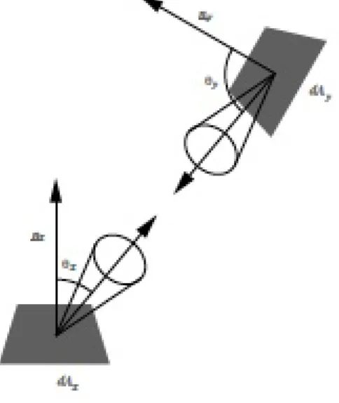
In fig. 2.1, assuming that the medium between point ~x and ~y does not participate in the light transport, we can easily deduce that L(x ← y) = L(y ← x), by computing the energy transport between them, and as a con-sequence the radiance does not attenuate with distance. This accounts also for the fact that an human observer, or a camera, which are sensitive to ra-diance perceive the same colour or brightness independently of the distance of the object. However, this property is not valid if the medium between the points is a participating medium, which will inevitably absorb and scatter light energy.
2.1. Radiometry 11
Figure 2.1: Energy transport between two differential surfaces.
In computer graphics, namely in global illumination, once the incident and exitant radiance is known for all surface points, then it is possible to compute the light energy transport through the all three-dimensional scene to generate the final image representation. Since computer graphics also aims a balance between computational resources and reliable physical models if the medium is non-occluding, such as air, it is approximated to vacuum, meaning that the medium will not be taken into consideration, in any computation.
All the above measures and quantities are also dependent on the wave-length of the light energy under consideration. As stated by Nicodemus et. al. 1976 [Nic76] we can incorporate this dependency by considering that the above quantities are integral functions over the full spectrum of the wave-length. For the radiance with wavelength, also know as spectral radiance can be computed by simply integrating it over the full wavelength spectrum
L(x ← Θ) = Z
spectrum
but usually the dependency of radiometry terms is implicitly expressed. Radiance, due to the presented properties, is the most fundamental quan-tity used in computer graphics to produce a plausible physically based image to present to the user, and the global illumination algorithm compute its value, for each visible point from the user viewpoint.
A more complete radiometry introduction can be found in the book by McCluney [Ros94] and by Nicodemus in [Nic76].
2.2
Light and Material interaction
The material, and specially the interaction between the material and light en-ergy, plays an important role in modelling the scene. Materials have different behaviours under the same lighting conditions, changing the overall appear-ance of the object surface. Some materials will exhibit a diffuse behaviour, other will behave as mirrors or even have a transparent behaviour allowing us to "see" through the object. It is also easy to notice that a wall painted with a flat white color, such as "matte white" paint, will not have the same behaviour as a wall covered with perfect mirrors and that it will produce a different illumination result.
To fully model the light interaction with a surface material as presented in fig. 2.2 we need a twelve dimension function to cope with all the spatial, time and wavelength dependencies.
To explain the Figure 2.2 let us assume the light wave, with wavelength λi, emitted from a light source placed in the direction Θi = (θi, φi) relative
to the tangent plane at point ~xion the object surface, as a continuous source
of photons flowing in a straight line in the direction of ~xi. Considering the
instant t0 as the moment that the photon leaves the light source, it will take
ti to travel the distance between the light source and the surface point ~xi.
The energy of the photon will be scattered through the surface material and eventually leave the surface at point ~xrin an arbitrary direction Θr = (θr, φr).
2.2. Light and Material interaction 13
Figure 2.2: Geometrical properties of the energy transport. (from [MMS+04])
phenomena may occur and are known as phosphorescence and fluorescence. When phosphorescence occurs the material absorbs part of the energy of the photon and releases it slowly over time increasing the time gap between the instance ti and tr, this phenomena is easily observed in materials that seem
to "glow" in the dark. On the other hand, some materials are able to absorb part of the photon wavelength energy converting the absorbed energy to other forms of energy, such as heat or movement, and emitting a new photon with a longer, less energetic, wavelength (λr) exhibiting a fluorescence property.
Nevertheless, this generic 12 dimensional function is impractical to model, compute and specially to capture. Computer graphics light models aim to achieve a balance between the accuracy of the light material interaction model and the computation resources by dropping some of the physical phenomena involved. To reduce the complexity of the general 12D reflectance function, some assumption are made:
• light travels at infinite speed;
• the incident and exitant surface point are the same; • the material does not change the light wavelength;
The simplification reduces the accuracy of the light transport model but simplifies the computation. For instance, to assume that the light travels at infinite speed is not crucial for the human perception, since we are not able to perceive the velocity but it allows the rendering algorithms to use a steady-state approach to the image generation process. These simplification drop 3 dimensional dependencies reducing the function to a 9D function. Ad-ditionally, a 8D function known as bidirectional scattering-surface reflectance distribution function (BSSRDF) described Nicodemus et. al. 1977 [NRH+77] can be obtained by the discretization of the wavelength into three colour bands (RGB).
BSSRDF is one of the most complete material models used in computer graphics, which models all dependencies, except phosphorescence and fluo-rescence. Due to the complexity involved in modelling and capture of the BSSRDF it is not often used and is replaced by simpler formulation.
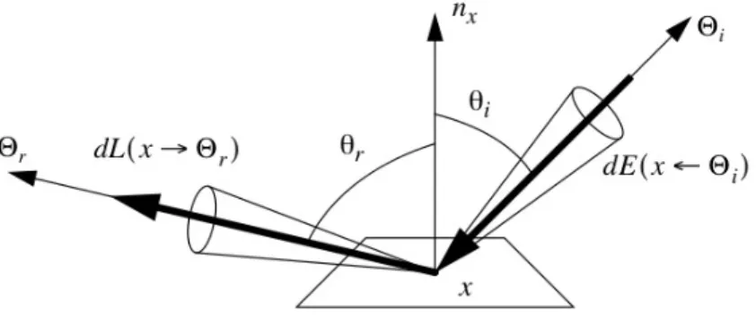
Bi-directional Reflectance Distribution Function (BRDF) is the most gen-eral model of reflectance used in computer graphics, at least at the level of detail that we are considering. The BRDF is defined as the ratio between the differential radiance reflected in an exitant direction, and the incident irradiance through a differential solid angle; or, more precisely, the BRDF is defined as the derivative of reflected radiance to incident irradiance
fr(x, Θi→ Θr) = dL(x → Θr) dE(x ← Θi) = dL(x → Θr) L(x ← Θi)cosθidωi (2.7)
and its values as to be positive and may exhibit different values for different wavelengths.
fr(x, Θi → Θr.λi) ≥ 0, ∀Θ ∈ Ω (2.8)
The basic concept of the BRDF (eq. 2.7) is illustrated in figure 2.3, showing the incoming light ray direction ( ˆΘi), the outgoing light direction
( ˆΘr) towards the observer viewpoint, both defined on the orthogonal axis
system formed by the normal ~n, tangent ~t and by the binormal ~b at point ~x .
2.2. Light and Material interaction 15
Figure 2.3: BRDF - Light reflection on surface material.
from each other. Therefore, the BRDF as defined in equation 2.7 behaves as a linear function in regard to all incident direction, and to compute the total amount of reflected radiance we must compute the sum of all contribut-ing light sources distributed over the hemisphere above the surface point, assuming that the surface is opaque and non-emissive, meaning that we must integrate equation 2.7 over the surrounding positive hemisphere (Ω+)
dL(x → Θr) = fr(x, Θi→ Θr)dE(x ← Θi) (2.9)
L(x → Θr) =
Z
Ω+
dωΘifr(x, Θi↔ Θi)L(x ← Θr)cos( ~nx, Θi) (2.10)
where cos( ~nx, Θi) is the cosine of the angle formed by the surface normal at
point x ( ~nx) and vector ˆΘ.
For a BRDF to be physically plausible it must observe two fundamental physical principles: reciprocity and energy conservation. The reciprocity, also know as the Helmholtz reciprocity, a principle that states that the paths fol-lowed by light rays can be reversed; if the incident and exitant direction are interchanged, and the value of the BRDF will remain constant:
fr(x, , Θi → Θr) = fr(x, , Θr → Θr) (2.11)
where the double arrow notation, in equation 2.12, indicates that the two directions may be freely interchanged. The energy conservation principle states that an object material can not reflect more energy than the received energy, but may absorb, or dissipate in another form of energy, a portion of the received energy
Z
Ω+
fr(x, Θi → Θr)cos( ~nx, Θr)dωΘ≤ 1, ∀Θi∈ Ω+ (2.13)
In general, BRDF’s are considered anisotropic, meaning that if the inci-dent and exitant are rotated about the surface normal at point ~x its value will change. Nevertheless, there are many materials where the value of the BRDF does not depend on a specific orientation of the surface, and are considered as isotropic.
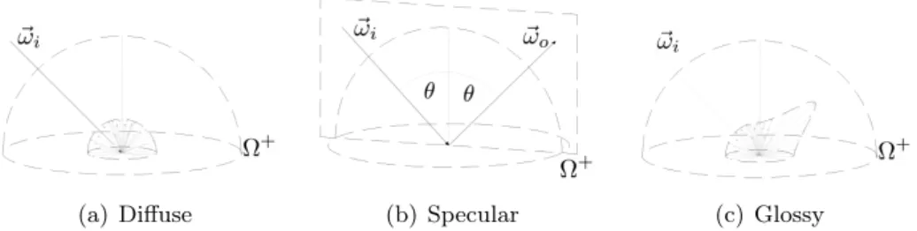
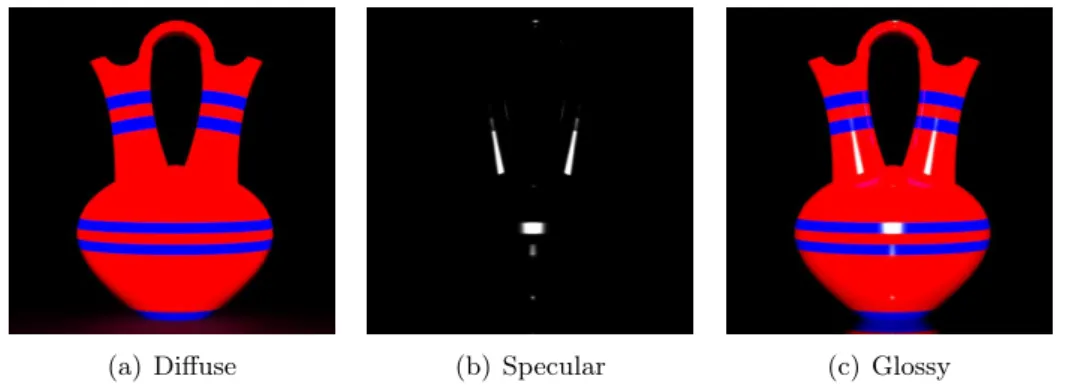
BRDF typically describe opaque materials, and the reflection properties depend on the material the object is composed of (e.g. metal or plastic), surface structure (e.g. rough or polished) and on homogeneity of the material across the surface. Depending on the nature of the BRDF used, the material appearance will be denoted as diffuse (fig. 2.4(a) and 2.5(a)), specular (fig. 2.4(b) and 2.5(b)) or glossy (fig. 2.4(c) and 2.5(c)).
(a) Diffuse (b) Specular (c) Glossy
Figure 2.4: Bidirectional Reflectance Distribution Function albedo
Diffuse reflective materials are characterised for distributing the same por-tion of incident light uniformly in all direcpor-tions. Diffuse or Lambertian reflec-tion are view independent, i.e., the illuminated surface looks the same to the observer independently of the its viewpoint direction (fig. 2.4(a) and 2.5(a)).
2.2. Light and Material interaction 17
(a) Diffuse (b) Specular (c) Glossy
Figure 2.5: Material appearance
Specular surfaces behave as perfect mirrors and they only reflect light in one specific direction, meaning that, according to Snell’s law, the incident and exitant direction make equal angles with the surface’s normal and are both coplanar with the surface normal(fig 2.4(b)). To determine the direction of the light reflection we only need to compute:
R = 2(nx.Θi)N − Θi (2.14)
However, perfect specular surfaces are an ideal mathematical concept, since the surface has only one exitant direction for which the BRDF is different from 0; therefore the value of the BRDF along that direction is infinite. There are no perfect specular materials in the real world, but some can exhibit this behaviour very closely.
Most surfaces are not perfectly diffuse, and it has been already stated that there are no perfect specular surfaces, so they all are a combination of both reflectance behaviours. In literature these surfaces are often called glossy surfaces, and their BRDF is difficult to model with a single analytical formula.
Although we have limited the scope of the work to opaque materials it is important to mention that some surface materials present a "transparency"1 behaviour. Strictly speaking, the BRDF is defined over the entire sphere
1
of directions (4π steradians) around a surface point, and the "transparent" side of the BRDF (in this case called bi-direction transmission distribution function BTDF) also exhibits properties such as diffusion, specularity and glossyness depending on the characteristics of the materials.
Real materials can have complex BRDF models; nevertheless, various analytical models have been proposed to simulate its behaviour. One of the simplest models proposed for diffuse surfaces is the Lambert’s model. Since the amount of exitant radiance is equal in all possible directions over the enclosing hemisphere, the Lambert’s model reduces the BRDF to a constant value
fr(x, Θi → Θr) = kd= ρr/π (2.15)
Another, historical, model was presented by B. Phong in [Pho73] that adds to the lambertine model the specular coefficient to create the appearance of glossy surfaces, becoming popular to the point of being directly supported by GPU hardware,
fr(x, Θi → Θo) = ks
R.Θnr N.Θi
+ kd (2.16)
since the specular surfaces reflect light along a specific direction R computed from equation 2.14. However, this model does not cope with the two physical constrains of BRDF’s, the energy conservation principle and the reciprocity principle. The later proposed modified Blinn-Phong model solves some of these problems, but not all, and is formulated as
fr(x, Θi→ Θo) = ks(N.H)n+ kd (2.17)
where H is the halfway vector between Θi and Θr. However, this model is still not able to capture the realistic BRDF’s behaviours.
Some analytical models present suitable behaviours to model real world surfaces and they will be introduced in an informal way since they are not in the scope of this work.
Cook and Torence in [CT82] assumed that a surface is composed of a collection of randomly distributed micro-facets to create their BRDF model
2.3. Modelling and Acquisition 19
and additionally they also included the Fresnel reflection and refraction terms,
fr(x, Θi → Θr) = F (β) π D(θh)G (N.Θi)(N.Θr) + kd, (2.18)
where F is the Fresnel reflection term, the micro-facet distribution is modelled in D and term G models the geometric shadowing.
Ward et. al. 1992 [War92] presented a BRDF model similar to the Phong model, but replaced the cosine term to a power by an exponential function. This model simulates the surface micro-structure variation, as it appeared in previous optics literature, by averaging the slope of the microscopic surface roughness and using it as a parameter for the exponential term.
Another often used model was presented by Lafortune et. al. [LFTG97] by generalising the original Phong models, but describes specular lobes arround any axis defined with respect to the surface instead of peaks of reflection arround the specular direction; the general formulation can be expressed as
fr(Θi → Θr) = fr(u → v) = ρs(Cxuxvx+ Cyuyxy+ Czuzvz) (2.19)
where u and v are the directions Θi and Θr, in orthogonal axis form by the normal at the incident surface point. The coefficients Cx, Cy and Cz
determine the size and the direction of the lobe while ρsdefines how narrow it is. This model adds also the ability to model retroreflectance property, which is the tendency of some surface materials to reflect the specular component in the direction of the light source.
2.3
Modelling and Acquisition
Generating images that realistically represent materials and object surfaces is one of the most challenging fields of computer graphics. Traditionally, surface geometry models only capture surface details on the triangular meshes up to a certain scale. The microscopic features that influence the reflectance behaviour are simulated through the analytical BRDF models.
This approach is not suitable nor designed to address the modelling of realistic appearance of all real world materials, and due to the lack of corre-spondence with some of the most interesting physical effects that are difficult to parameterize. However, very limited group of materials, such as metal and shinny plastic, can be efficiently approximated by this approach. The diffi-culty of parameterization of the analytical BRDF model is even higher when the material requires the modelling of the meso structures present at most surfaces, which play an important role in the appearance of the surface ma-terial and are between the macro-scale structures captured in the geometry and the micro structures modelled in the analytical BRDF’s.
Some mesoscopic and microscopic structures can be modelled using nor-mal or bump mapping. Nornor-mal maps, or bump maps [Bli77], can be used to transform flat surfaces into curved surfaces by introducing a new per-texel normal to be used in the BRDF evaluation process instead of the surface’s geo-metric normal. Driven by the limitation posed by traditional surface material modelling and the increasing size of memory available in computer graphics cards, image based techniques together with normal mapping are becoming increasingly important, but they fail to accurately represent the surface and material appearance since they are not able to express the light and view dependency of the material.
Some researchers have proposed several distinct approaches to overcome the limitation of the traditional surface material modelling. The most com-plete model used in computer graphics, presented by Nicodemus [NRH+77], is the 8D BSSRDF, which is able to cope with most of the phenomena present at the 12 parameters of the generic function. BSSRDF require the modelling and estimation of 8 different parameters, which are highly demanding in terms of computer resources, acquisition systems and time requirements. To reduce the complexity of the capture, fitting and rendering processes of real world surface material some authors reduce the complexity of the BSSRDF model by dropping some of the physical dependencies, which limits its use to a par-ticular subset of materials. Fig 2.6 presents a taxonomy adpated from [RM] which represents some of the different levels of simplification possible from the generic 12 function. Opaque homogeneous materials do not require the
2.3. Modelling and Acquisition 21
Figure 2.6: A hierarchy of reflectance functions according to taxonomy adapted from [RM]
modelling of a complete BSSRDF. They can be modelled with a simple 4D BRDF, since they do not exhibit a spatial dependency across the surface. Nicodemus [NRH+77] presented a gantry named gonioreflectometer able to place a light sensor, traditionally a spectroreflectometer able to acquire a dense reflectance sample at a single surface point or integrated over a surface area, and a calibrated light source in different angles relatively to the sam-pled surface material in order to obtain a complete set of samples required to estimate the 4D BRDF parameters.
The gonioreflectometer was used by Murray-Colemann et. al. 1990 [MCS90] (fig. 2.7) in his light studies and later adapted to computer graphics by Sing-Choong Foo in his master thesis [Foo97].
Ward et. al. [War92] proposed a similar device in 1992 (fig. 2.8) using image based technology instead of spectrometer to measure the BRDF. The
Figure 2.7: A gonioreflectometer designed by Murray-Coleman and Smith ( from [MCS90])
key elements of Ward approach are a half-silvered plastic hemisphere and a CCD camera with a fish-eye lens. The combination of the hemispherical mirror and the CCD camera accounts for two of the required degrees of free-dom without the mechanical constrains by capturing in a single image a wide number of viewpoints. This approach reduces the time required to capture BRDF samples; however, it requires careful calibration to allow the retrieval of the individual viewpoints. These approaches assume that the material is sampled from a flat surface; however, the approximation can be achieved by using instead a spherical surface, as proposed by Marschner et al.[MWL+99] and later used by Matusik et al.[MPBM03] to measure isotropic BRDFs.
Some authors went further in the acquisition of surface reflection proper-ties by trying to incorporate the spatial dependency into the final represen-tation, using image based approaches, limiting, or dropping, some of the re-quired degrees of freedom of a complete 6D BRDF. Light fields and reflectance fields are two types of techniques that fall into the category of image-based rendering.
2.3. Modelling and Acquisition 23
Figure 2.8: Ward’s silver hemisphere reflectometer (from [War92])
Light fields became popular with the work of Levoy et. al.[LH96] and Grotler [GGSC96], and describe a set of acquisition techniques that capture the spatial dependency using various viewing angles but neglect the light source direction. The light fields [LH96] and in the lumigraphs [GGSC96] the different samples are acquired using a single light source with a fixed position in space and each image sample, captured with a CCD device, represents a different view angle of the material surface.
Reflectance fields, on the other hand, neglect the viewing direction. A reflectance field is captured using a fixed CCD device and each image register the surface reflectance of the material sample under different illumination angles. Reflectance fields where first explored by Debevec et. al. [DHT+00] to capture the appearance of human faces in a device he called light stage where the face of an actor is placed in the centre of a dome while, a light source rotates around him. A reflectance field technique is also the basis of Malzbender et. al. approach [MGW01] presented in the next chapter.
Dana et. al. [DvGNK99] in her studies of computer vision developed a method to capture a complete sample of the 6D BRDF, which is known as Bidirectional Texture Function (BTF). BTF where not developed to address
Figure 2.9: BTF capturing device at Columbia University (from [DvGNK99])
model the Spatial Varying BRDF (SVBRDF) or Apparent BRDF (ABDRF) behaviour of the surface material, but to address problems related to com-puter vision tasks, such as texture recognition, texture segmentation and shape-from-texture.
Several authors proposed different acquisition system for the BTF ap-proach that can be summarised in three catagories: goniorefloctometer-like, which use some sort of mechanical gantry, a parallel version of the latter using an array of cameras and an approach using mirrors.
The gonioreflectometer-like approach is similar to the classic BRDF mea-suring setup, but uses instead a CCD camera to enable the sampling of the spatial dependence of the BTF. Dana et. al. [DvGNK99] was the first to present a proposal based on a goniorefloctometer-like setup (fig. 2.9). They used a setup with a fixed and calibrated light source with fresnell filters to parallelize the light, a 640x480 CCD camera, which could be moved around the sample and a robotic arm to rotate the sample in order to account for the remaining required degrees of freedom. With this approach Dana was able to acquire 205 images for each of the 61 samples of real world isotropic materials publicly available on the CUReT database [CU]. While the coarse nature of the sample acquisition is not suitable for high-quality rendering, the main goal of the measuring work done was the acquisition of texture samples for computer vision related tasks, such as texture recognition, segmentation and shape-from-texture. Although the required time for each sample was not
2.3. Modelling and Acquisition 25
reported, by taking into account the time required to measure a single 4D BRDF with a similar device, it is plausible to assume that it is time consum-ing. A major disadvantage of the samples that are available is that they are not rectified in the acquisition stage, requiring tedious and time consuming steps to address the problem through computer vision strategies to project each image of the sample onto the same plane in order to rectify it.
McAllister et. al. [MLH02] proposed a similar but improved approach. McAllister also proposed the fitting of the acquired data to an analytical BRDF model per pixel, thus obtaining a SVBRDF. A small number of mate-rials were sampled and are available online for research purposes.
Sattler et. al. [SSK03] replaced the low resolution CCD camera used by Dana with a 13.5 Mpx (4500x3000 pixels) camera. The system can also acquire a denser sample of the angular domain by capturing 6561 images per material sample, instead of the original 205 images. This dense sampling takes 14 hours to acquire, but the authors claim to have acquire a wider variety of material samples, which are online at the Bonn BTF database [oB]. As an improvement to the samples available at the CUReT database, the images in the Bonn BTF database are all registered and rectified.
The main disadvantage of the gonioreflectometer-like setup is the required mechanical movement, which takes time to move each individual element and to post-process each image. The solution allows some flexibility in choosing the element that will be allowed to move (light source, image sensor or ma-terial sample) as long as the required degrees of freedom are met. With this premise in mind, a system can be designed to minimize the time required for the acquisition. Sattler et. al. [MMS+04], inspired by the approach followed by Malzbender et. al. [MGW01], proposed a system based on an hemispher-ical array of 151 digital cameras that were mounted on a rigid hemispherhemispher-ical dome, which due to the parallel nature of the system reduce the acquisition time to about an hour, taking advantage of the fact that the required im-age rectification step is trivial since there is prior knowledge of the camera positions.
the BRDF acquisition. Following the same basic idea Han and Perlin [HP03] used an array of mirrors to acquire a BTF. Their system uses a kaleidoscope to obtain in the same image the required different view angles, therefore reducing the amount of time and the required image storage space. A major advantage is that the system has no moving parts and consequently the image registration step is simple; on the other hand, each acquired image is of low quality and requires image colour calibration due to the multiple reflections in the mirrors and to the fact that the mirrors are not perfect.
The acquisition of real-world surfaces using a BTF approach will lead to the generation of huge amounts of data. Dana et. al. [DvGNK99] originally used a tabular representation, and developed an interpolation algorithm to render the material from the collected samples. However, this approach is time consuming and does not cope well with real time rendering requirements. Some of the proposed analytical models, as the ones presented on the previous section, are in some extent available on current GPU cards or they are not difficult to implement.
McAllister et. al. [MLH02] proposed a solution to the compression of the BTF by fitting the data onto Lafortune BRDF model. However, to accom-plish the estimation of the BRDF model parameters he had to assume that the surface meso-structures are nearly flat, although composed of different materials. The final representation of the BTF is described in a tabular form, where each element represents a point in the 2D space (texel), and for each texel a Lafortune model is fitted using a non-linear optimization method, in this case Levenberg-Marquard. Although the storage of the parameters is done on a similar method to traditional 2D texture, the major drawback is that Lafortune lobes fitting is not straight forward, specially when using Levenberg-Marquard optimization, as reported by the authors. Nevertheless due to the assumption of near flat meso-structures, this approach is restrict to materials that do not exhibit masking and shadowing. To overcome this limitation Daubert et. al. [DLHS01] proposed an additional view dependent scaling term to model the occluding effects. The additional parameter is stored in each pixel as a lookup table for each view direction and interpo-lated between measured viewing directions, which allows its computation on
2.3. Modelling and Acquisition 27
graphics card hardware, as successfully used by the authors to render cloth materials.
Meseth et. al. [MMK03] proposed the use of light or reflectance fields to compress the BTF data. They noted that the changes in the light di-rection are smoother that changes in the view didi-rection, which was already observed by Malzbender mainly for diffuse surfaces [MGW01], and therefore the signal in reflectance fields have a lower frequency than the signal in light fields, which makes them a suitable candidate to approximation by a simple analytical function. Since for each view direction the reflectance field is ap-proximated in each texel by a simple analytical model, the authors proposed the interpolation between the measured view points using a weighted set of closes view directions reflectance fields [MMK03, MMK04].
Until now all the presented approaches to BTF compression use some form of analytical or polynomial model, that in many cases is not suitable for high frequency reflectance signals that arises from shadowing and masking. Some authors proposed a different approach based on the fact that the measured BTF data can be considered a multi-dimensional signal, where the signal processing techniques can be applied to find a more suitable basis function for the data. This approach implies the reorganization of the measured data into 2D arrays to allow the use of linear algebra techniques such as principal component analysis (PCA) and singular value decomposition (SVD). The main different between the proposed strategies differ in the way the data is distributed in the array: McCool et. al. [MAA01] applies a per texel linear decomposition on the per texel ABRDF and tries to find a set of lower dimensional factors to approximate them, while Liu et. al. [LHZ+04] reorders the array so that for each texel in the BTF the discrete ABRDF is a column in the array and then applies a PCA to the complete BTF, keeping only the first k components of their BTF approximation. The latter approach lead to a large array size, which makes the PCA approach highly computation demanding. Hauth et. al. [HEE+02] and Sattler et. al. [SSK03] proposed that the PCA approach be applied only on a view dependent basis only, therefore they only apply the PCA approach to a single slice of the BTF with fixed view direction, and consider each fixed view direction independent from
each other.
Describing the full problematic surrounding the BTF approach would be tedious and out of the focus of this work, therefore we suggest the reading of a STAR report by Muller et. al. [MMS+04] at Eurographics, which includes all the related problems with BTF acquisition, compression, decompression and rendering, as well as comparative analyses of all proposed approaches by other authors.
All of the briefly described approach to model the BSSRDF, the SVBRDF or part of it poses problems when the final goal is to create a digital surrogate that must withstand the scrutiny of the scientific method and address prob-lems related with long term digital archive. Some rely on skilled professional to tune the parameters of the analytical models to described the acquired data, others raise problem of defining the level of information that must be represent, while others create a problem by requiring huge amounts of storage spaces that are not compatible with long-term digital preservation.
The RTI approach purposed by Malzbender et. al. [MGW01], is far from being able to represent the full reflectance properties of a surface. However, it is shown in the following chapters provides a solid mathematical background that can be easily validated, adds value to traditional photographic workflows used by CH and NS professionals and the processing workflow can be easily automated to allow repeatability and the automatic gathering of empirical provenance.
Chapter 3
Reflectance Transformation
Imaging
The surface reflectance properties of an opaque material can be modelled us-ing a 4D BRDF associated to an infinitesimal point in the object surface. All contributing factors, such as meso-structures and micro-structures, are in some way modelled in the object geometry, in the BRDF model or through normal maps. These approaches require some user handling, which may im-pair the photorealistic quality of the final rendered image. The user handling do not enable the reproducibility of these type of approaches, which make them incompatible with the digital surrogate philosophy.
Several methods have been developed in the last decade for better mea-sured approximation to 6D BRDF that differ in complexity and accuracy. Image based re-lighting [AS02, DHT+00, DWT+02, MGW01, WAA+00], also known as reflectance fields, only extracts a slice of the complete 6D BRDF since the capture is limited to a set of images taken from a single viewpoint un-der different illumination directions. The processing, and compression, of the acquired information distinguishes the different reflectance field approaches, which range from the most simple tabular format to complex analytical mod-els fitting.
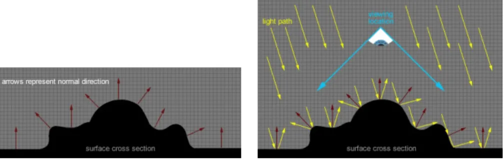
Reflectance Transformation Imaging (RTI) presented by Malzbender et.
al. at HP Labs [MGW01], is one of the reflectance field techniques. The dis-tinctness of the RTI approach lies in the compression. Malzbender proposed the use of Polynomial Texture Maps (PTM) to handle the compression of the acquired data. The PTM approach stores per pixel the fitted coefficients values of a polynomial function. Although the polynomial approach increases the time required to compress the acquired data, it reduces the decompres-sion stage to a single evaluation of the polynomial function for any given light direction (fig. 3.1) and allows the recovery of surface information such as sur-face normals, which enables the development of sursur-face details enhancement techniques.
(a) Surface cross section with normal infor-mation
(b) Sampled light-surface interaction cap-tured in single image
(c) Final surface re-lighting using PTM’s
Figure 3.1: Basic Reflectance Transformation Imaging concepts (kind permis-sion of Mark Mudge)
The Natural Sciences (NS) and Cultural Heritage (CH) professional soon realised the potential of the technique due to the simplicity of the capturing method, the final representation format and to the amount of information that can be recovered from the polynomial function.
3.1. Image acquisition 31
The next section is dedicated to methodology of the acquisition stage of the RTI approach, and the solution proposed for different problems related mainly with the scale of the object surface. Section 3.2 will address the PTM proposed by Malzbender to handle the compression stage of the acquired data and different application of the PTM approach. Section 3.3 targets the surface information recovery from the PTM approach and how it can be handled to enhance selected surface details.
3.1
Image acquisition
The RTI approach is a photometric technique, which requires the acquisition of multiple images of a static object with a fixed camera under varying lighting conditions, similar to the work by other authors such as Debevec in [AS02] and Georghiades in [GBK99]. In the reflectance fields the camera position does not need to be known since the view-dependent phenomena are deprecated in favour of light-dependent phenomena, but the compression stage requires as input the captured image set and the 3D vector that specify the direction of the light source for each image. Several different ways can be used to estimate the light source direction for each image, that vary in complexity, cost and precision.
The original method proposed by Malzbender uses rigid domes where the position of each light source position to the target surface at the centre of the dome, is fixed and known. Depending on the size of the objects the dome approach may have drawbacks that do not allow its use. To cope with these drawbacks, specially with medium to large scale objects, professionals have suggested that the light sources could be manually placed, and their position could be either measured during the shooting session, or could be estimated from highlights in glossy spheres or shadows cast from small sticks near the targeted surface [DHT+00, DCCS06, CDMR04, MMSL06].
The dome style approach establishes a fixed distribution for light sources positions that can be later used by the compression stage. The dome style approach can to decrease the acquisition time and varies in complexity and
(a) Basic icosahedron dome (b) HP labs automated dome (c) CHI automated dome
Figure 3.2: RTI capturing domes ((a) and (b) kind permission of Tom Malzbender, (c) kind permission of Mark Mudge)
cost. The simplest dome is shown in fig. 3.2(a), which requires the photog-rapher to manually reposition the light source to a vertex of the icosahedron after each shot. Fig. 3.2(b) shows a dome, built for the Antikythera Research Project [FBM+06b], with 50 different computer controlled light sources that dramatically reduces the capturing time. The Cultural Heritage Imaging foundation (C.H.I.) took the dome concept even further by introducing con-trolled wavelength light emitting equipment, allowing their dome to be used with artefacts sensitive to specific wavelength such as ultra-violet. The dome style technique was proven suitable for small objects such as coins [MVSL05], small archeological artefatcs [FBM+06b] or small fossils [HBMG02].
Debevec used a dome style approach to capture reflectance fields of human faces, which required a dome with considerable size [DHT+00]. However, cultural heritage and natural sciences are full of examples of medium to large scale object. The dome style approach in these particular cases is at the most impractical, either due to the size of the dome required or to some physical constraint posed by the artefact or the surrounding environment, such as artefact handling restrictions or the existence of physical barriers.
3.1. Image acquisition 33
on a pre-planning of the light source distribution taking into account the size of the artefact to be captured and the surrounding physical constraints. This approach requires careful measuring to position the pre-computed light sources.
Dana et. al. [CDMR04] used instead a small stick to record the light source direction for each photograph. The projected shadow into a white backgrounds, was later used to recover the light direction for each sampled image. Debevec et. al. [TSE+04] introduced glossy spheres to record the highlights on the surface, for each sampled light direction.
Mudge et. al. [MMSL06] extended the idea into the RTI, recovering the light directions from highlights recorded on a black glossy sphere, placed near the object and captured during the shot session, using simple geometry based on the estimated sphere centre and radius and the relative position of the highlight to the centre of the sphere. The technique is known as Highlight based RTI (HRTI).
Mudge also suggested that each image could be analysed to retrieve the sphere centre and radius, along with the relative highlight location using a computer vision approach. This suggestion led to the theme of this thesis and to the development of a software package, the RTIbuilder, that automates the HRTI acquisition pipeline: search the black sphere, find its centre and radius, estimate the centre of the highlights at each sphere image, compute the light directions and generate the final RTI compressed representation.
The combination of the acquisition techniques, dome and highlight based, can address most of the problems posed by the CH and NS communities. The simplicity of both approaches, and specially the freedom to place the light sources in the highlight based approach, eases the acquisition of a fair representation of an artefact. The highlight based approach was able to take the technique from the laboratory to the field and to cope with working restrictions in remote and isolated locations.
Due to this reduced set of requirements, the RTI acquisition approach is also able to offer a low cost alternative to NS and CH professional, as it
Figure 3.3: Same images of the Piscos Man set at Coa Valey Archeologic Park, images taken using highlight based RTI.
Figure 3.4: Combination of Dome and Highlight based techniques in the D. Diogo de Sousa Regional Archeological Museum.
was demonstrated in the dome built for the Regional Archeological Museum D. Diogo de Sousa. This dome was built using a "papier-mâché" technique (fig. 3.4) and the light source directions were estimated using the highlight based approach. This low cost approach demonstrates that as long as the requirements for the RTI compression stage are met, the acquisition is only limited by the imagination.
3.2. RTI compression stage 35
3.2
RTI compression stage
The acquisition stage generates a large set of images. With a 12Mpx digital camera these sets will require large amounts of storage space (several GB). Although a range of different compression techniques can be used [MMS+04], most of them will store the information in a tabular format, where an ar-ray containing the sampled information is stored for each light direction and pixel. The stored information can the be used to interpolate between the sample light directions to compute the colour values for any unsampled light direction. In this approach the computational intensive task is on the decom-pression stage.
Malzbender observed that in the samples stored at each pixel the chro-maticity remained fairly constant across the sampled light directions and that the luminance accounted for most of the apparent colour change. To express this colour dependence on luminance (L(u, v)) at a particular point in the surface (u, v), Malzbender computes the colour of a new light direction using the following equations:
R(u, v) = L(u, v)Rn(u, v)
G(u, v) = L(u, v)Gn(u, v)
B(u, v) = L(u, v)Bn(u, v)
where (Rn(u, v), Gn(u, v), Bn(u, v)) are a computed unscaled colour in RGB
format model. The RGB model was chosen since it is the colour model for most digital cameras, and the conversion to other models, although surveyed, would require additional computation resources.
The second observation that Malzbender made was that for diffuse ob-jects: even with high spatial frequency variation, the dependence of lumi-nance on light directions was very smooth. Combining the two empirical observations, he suggested that the compression of the acquired data could be achieved by approximating per pixel the luminance term to a bi-quadratic
polynomial function:
L(u, v, lu, lv) = a0(u, v)lu2+ a1(u, v)lv2+ a2(u, v)lulv+ a3(u, v)lu
+a4(u, v)lv+ a5(u, v) (3.1)
where u and v are the spatial coordinates on the texture, and the light di-rection dependency is express by (lu, lv) that represent the light direction
projected vector into the tangent plane of the local coordinates system. The bi-quadratic polynomial function expresses the dependence of the luminance term on light direction, which were registered for each captured image during the acquisition stage. The unscaled colour for each pixel can be easly computed for each individual colour channel in RGB format, then the coefficients (a0..a5) from eq. 3.1 can be computed by solving the following
linear system: l2u0 l2v0 lu0lv0 lu0 lv0 1 l2u0 l2v0 lu0lv0 lu0 lv0 1 .. . ... ... ... ... ... l2u0 l2v0 lu0lv0 lu0 lv0 1 . a0 a1 .. . a5 = L0 L1 .. . LN
where N is the number of sampled images. To solve this linear system Malzbender computes the best fit in the L2 norm using a singular value decomposition (SVD) algorithm. The solution is further simplified by assum-ing that the light direction variation across the acquired surface is negligible. The simplification, although introducing inaccuracies, has the advantage of only requiring a single SVD computation for a given light direction config-uration, which can be applied to each individual texel, reducing dramati-cally the required computational time. Once the coefficients for an individual texel are determined, they are stored, along with the chromatic information (Rn, Gn, Bn), in a spatial map known as a Polynomial Texture Map (PTM).
The bi-quadratic polynomial functions will be approximated using only a discrete set of values, and consequently will smooth some light effects such as high specular spikes or hard shadowing. The smoothing effect is visible in
3.2. RTI compression stage 37
the final representation, but only will affect the light space, preserving any spatial dependencies even when the surface exhibits high spatial frequencies. The PTM approach will also convert any point light source into an area light source due to the light direction variation simplification across the surface.
Common sense would expect that by increasing the number of sampled light directions the accuracy of the approximation would increase indefinitely. Scopigno et. al. [DCCS06] did show that computing the difference between normal maps reconstructed from the PTM’s generated from the same im-age set with different number and distribution of light sources, he was able to determine that with a carefully distributed light direction sampling, the threshold was found to be 80 photos. He specifically determined that a set composed of 70 to 80 images would represent the best relation between acqui-sition effort and accuracy.
The described PTM format stores for each individual texel the value of luminance and the computed chromatic RGB values and is known as LRGB PTM. However, for some applications it is preferable to apply the bi-quadratic polynomial to the individual colour channels and on the RGB PTM. The fitting process is applied directly to each colour channel, storing 6 coefficients per colour channel. The RGB PTM enables the use of the PTM approach on surfaces where the chromatic values varies significantly, due to self-shadowing for instance, or when used to encapsulate unidirectional behaviours, such as time-lapse or depth of focus.
Bump maps are required by traditional texture mapping to introduce small perturbations on the surface normal to achieve a more realistic look&feel, and Malzbender provided mathematical tools to convert then into the PTM format [MGW01]. This step is not required for an acquired PTM, since it already encapsulates the behaviour. PTM’s were designed to capture the behaviour of mainly diffuse surfaces and, as seen before, the approach will smooth the specular spikes of the surface, but they can be reconstructed, or ar-tificially recreated, using the recovered surface normal’s techniques described in the next session. The original work in PTM [MGW01] also includes some transformation to allow its use to encapsulate behaviours such as anisotropic,
fresnel and off-specular effects.
3.3
PTM surface enhancement
The bi-quadratic polynomial function stores the BRDF behaviour at a par-ticular point in the surface. The normal at this point can be computed and using the knowledge from radiometry and light surface material. Since the surface is assumed to be mainly diffuse, the surface normal can be computed from eq. 3.2 by determining the maximum luminance value of the function.
L(u, v, lu, lv) = a0(u, v)lu2+ a1(u, v)lv2+ a2(u, v)lulv+ a3(u, v)lu
+a4(u, v)lv+ a5(u, v) (3.2)
The bi-quadratic polynomial function describes a 2 dimensional parabola and the maximum luminance projected vector can be determined by
lu0= a2a4− 2a1a3 4a0a1− a22 , ∀a0,a1,a2 : (4a0a1− a 2 2) > 0) ∧ a0 < 0 (3.3) lv0= a2a3− 2a0a4 4a0a1− a22 , ∀a0,a1,a2 : (4a0a1− a 2 2) > 0) ∧ a0 < 0 (3.4)
where lu0and lv0 are the projected values of the surface normal, then normal can be recovered as ~ N = (lu0, lv0, q 1 − l2 u0− l2v0), ∀lu0,lvo : 0 ≤ (−l 2 u0− l2v0≤ 1) (3.5)
The ability to recover the surface normal field enables the artificial re-construction of the specular information using for instance the Blinn-Phong analytical model. Specular enhancement enables the observer to discover fea-tures that can not be seen with regular light condition, as shown in fig. 3.5 where the inscription on the bottom of the plate can be easily seen and the inscription has a better overall readability when using this enhancement.
The second enhancement method proposed by Malzbender, is to modify the coefficients, by computing new values to increase the directional sensitivity
![Figure 2.2: Geometrical properties of the energy transport. (from [MMS + 04]) phenomena may occur and are known as phosphorescence and fluorescence.](https://thumb-eu.123doks.com/thumbv2/123dok_br/17952880.853858/24.892.200.709.207.496/figure-geometrical-properties-energy-transport-phenomena-phosphorescence-fluorescence.webp)
![Figure 2.6: A hierarchy of reflectance functions according to taxonomy adapted from [RM]](https://thumb-eu.123doks.com/thumbv2/123dok_br/17952880.853858/32.892.289.600.225.597/figure-hierarchy-reflectance-functions-according-taxonomy-adapted-rm.webp)
![Figure 2.7: A gonioreflectometer designed by Murray-Coleman and Smith ( from [MCS90])](https://thumb-eu.123doks.com/thumbv2/123dok_br/17952880.853858/33.892.232.662.227.524/figure-gonioreflectometer-designed-murray-coleman-smith-mcs.webp)
![Figure 2.8: Ward’s silver hemisphere reflectometer (from [War92])](https://thumb-eu.123doks.com/thumbv2/123dok_br/17952880.853858/34.892.233.660.222.499/figure-ward-s-silver-hemisphere-reflectometer-from-war.webp)
![Figure 2.9: BTF capturing device at Columbia University (from [DvGNK99])](https://thumb-eu.123doks.com/thumbv2/123dok_br/17952880.853858/35.892.247.641.223.389/figure-btf-capturing-device-columbia-university-dvgnk.webp)