Influence of Si Coating on Interfacial Microstructure of Laser Joining of Titanium and
Aluminium Alloys
Aline Capella de Oliveiraa*, André Felipe Ribeiro Moreiraa, Carina Barros Mellob, Rudimar Rivac,
Rogério de Moraes Oliveirab
Received: December 20, 2016; Revised: September 01, 2017; Accepted: October 05, 2017
A common phenomenon in the dissimilar joints is the presence of brittle compounds in the joining interface region. The brittle phases can decrease by introduction of interlayers in the joining interface, such as silicon, that inhibits the formation of Al3Ti and AlTi3 phases in joining process between titanium and aluminium alloys. In the present work, the joining of titanium and aluminium alloys
have been carried out using a Yb:fiber laser, considering the prior silicon film deposited on titanium
alloy interface by DC magnetron sputtering. Butt joint conditions were maintained constant: laser average power, process speed and beam positioning along the interface joining toward aluminium alloy (1200 W, 3.0 m/min and 0.3 mm, respectively). Metallographic analyses were carried out on the cross-section joint by optical and electronic microscopies. When the melted aluminium alloy wet the solid-state titanium alloy, a more restrict compound layer was formed in the joining interface. EDS line scanning in the joining interface showed a reduction of compound layer thickness, considering
the silicon as interlayer, reaching the mean value of 3 µm, i.e., up to five times thinner if compared
to joining without silicon during the process.
Keywords: dissimilar metals, joining process, Ti-6Al-4V, AA6013
*e-mail: [email protected]
1. Introduction
The industrial demand for hybrid components has increased the necessity for joining dissimilar metallic materials1,2. Different techniques have been used for joining of
dissimilar metals such as diffusion welding, brazing, friction
stir welding, electron beam welding, and laser welding3,4.
Independently of the process considered, involving liquid or
solid states, brittle intermetallic compounds can be formed in the joining interface. These brittle phases degrade the material mechanical properties, promoting the formation of cracks during static or cyclic loads5. The joining between titanium and aluminium alloys, for example, generates the Al3Ti and AlTi3 intermetallic compounds that decrease the
joint quality6. Luo and Acoff7 analyzed the influence of reaction annealing temperature, time and atmosphere on the multilaminated composites of titanium and aluminium prepared by cold-roll bonding. Their results shown the formation of intermetallic compound Al3Ti in relatively short times at low reaction annealing temperatures, 600° C and 680° C.
Morizono et al.8 also investigated the interfacial reactions in
aluminum and titanium solid states, beside liquid aluminum
and solid titanium states, using explosive energy. According
to the authors, the intermetallic Al3Ti was formed along the aluminum and titanium interface in both conditions, being the layer thickness increased with the process holding time. Kimura et al.9 also suggested the influence of the friction time in the formation of intermetallic compound layer in friction welded joint between Ti-6Al-4V and Al-Mg alloys. In this case, an intermetallic compound, consisting of Ti2Mg3Al18, was observed at welded interface generating fracture of the joint in this region.
In equilibrium conditions, the formation of intermetallic
phases may be related to the system phase diagrams10. However,
in the non-equilibrium experimental conditions the stability
may not be present and knowledge of the parameters related to the formation of intermetallic layers to achieve a stable process is necessary.
In literature, different methods have been applied to inhibit
the formation of brittle intermetallic compounds in the joining interface of dissimilar metals1,11. Researches concerning the laser joining of titanium and aluminium alloys have shown that the thick intermetallic layer can be restricted only when the titanium alloy melts during the process. The high cooling rate inherent to laser processing decreases the interaction time between the melted aluminium alloy and the solid titanium alloy, promoting thinner intermetallic layers12,13.
aInstituto de Ciência e Tecnologia, Universidade Federal de São Paulo, São José dos Campos, SP, Brazil bInstituto Nacional de Pesquisas Espaciais, Av. dos Astronautas, 1.758, Jardim da Granja, São José dos
Campos, SP, Brazil
The brittle phases can be decreased by introducing of
filler metals, or thin sheets, in the joining14,15 interface. Chen et al.3 have introduced Al-12Si filler metal in the aluminium and titanium interface in the laser joining process. According
to the authors, the diffusion of silicon during the process
generates other compounds such as Ti7Al5Si12 and Ti5Si3, inhibiting the formation of the Al3Ti and AlTi3 phases. The
influence of silicon on aluminium and titanium joining interface during the vacuum brazing have been analyzed
by Takemoto et al.16. The authors observed the formation of multiple phases inhibiting the Al3Ti compound, improving the joint mechanical resistance. However, the introduction
of filler metals in the interface joining requires suitable
fasteners to ensure the thermal contact between the alloys to be joined, especially in the laser process. The main drawback refers to laser energy that is absorbed by material surface and conducted to interface region by thermal conduction, being
necessary a good fixation between the dissimilar materials. Different deposition techniques have been used in process
involving titanium substrate to improve its surface characteristics. Researches concerning the silicon deposition as interfacial layer between the alloy and DLC (Diamond Like Carbon)
films have been considered to improve the film adhesion to
the substrate involved17,18. Ti-6Al-4V alloy coated with SiO 2 has been considered for biomedical applications such as prostheses or implants19. Silicon deposition by DC magnetron
sputtering technique has been limited to applications in micro
and macro electronics such as insulator substrates and solar cells20. Combined DC-RF magnetron sputtering has also been carried out to obtain silicon epitaxy on silicon substrates21.
In the present work, the joining between titanium and
aluminium alloys have been performed using a Yb:fiber laser, considering the prior silicon thin film deposited by DC-RF
magnetron sputtering in titanium alloy interface. The main
goal of this research is to evaluate the influence of the control
of laser process parameters and of the introduction of silicon,
as filler material in the joining process, in the reduction of
intermetallic layer thickness formed in the joining interface between the titanium and aluminium alloys.
2. Experimental Details
2.1 Material and experimental setup
Sheets of titanium and aluminium alloys, AA6013-T4 and Ti-6Al-4V, with 1.6 mm and 1.0 thick, respectively, were used. The chemical composition of these sheets is presented in Table 1. All sheets were cut with dimensions of 20 mm x 25 mm, cleaned with abrasive paper (SiC grit 600) and ethanol to remove the residual grease and contaminants.
Prior to the joining process between the dissimilar metals, silicon deposition was carried out on a silicon substrate by magnetron sputtering powered by 300 V, 90 mA DC and 50 W RF sources (combined DC-RF) with 0.6 Pa work pressure and
argon ambient, for 30 min to determine the film thickness and
the deposition rate of the process. For this, the silicon substrate was partially covered with a mask on its surface, preventing
the deposition of the silicon film in this region. Thereafter, the sample was analyzed by using scanning electron microscopy
(SEM, JEOL JSM 6701S) to measure the height between
deposited film and the measurement substrate.
Considering the same experimental conditions (300 V, 90 mA DC and 50 W RF sources with 0.6 Pa work pressure and argon ambient), silicon was deposited on Ti-6Al-4V substrates with deposition time of 1 and 2 hours. In this case,
the silicon film was deposited on the longitudinal section of the substrate, to analyze the formation of possible defects of the film, and on its transverse section, to later junction
between the dissimilar alloys.
Afterwards, Ti-6Al-4V and AA6013-T4 sheets were joined using a laser joining system. Figure 1 shows the schematic diagrams of the laser joining system (Figure 1a) and the beam positioning along the junction interface toward to aluminium alloy (Figure 1b). Dissimilar metal sheets were
tightly champed and fixed on a XYZ CNC moving table. A high-power Yb:fiber laser with a 2 kW maximum power (IPG,
YLS 2000) was used in the experiments. With a lens of 160 mm focal length, the laser beam was focused on the sample with 100 µm estimated diameter22. Butt joint conditions were maintained constant and selected from the previous work23
based on the influence of the experimental parameters on the
formation of joints: laser average power, process speed and beam positioning along the interface joining toward aluminium alloy (1200 W, 3.0 m/min and 0.3 mm, respectively). Helium
with 20 L/min flow rate was used as shielding gas.
2.2 Microstructure analysis
The specimens were ground with abrasive paper (SiC grits of 240, 400, 600 and 1200, respectively), polished to
a mirror finish (1.0 µm Al2O3 solution and colloidal SiO2) and chemically etched using Keller's reagent (2 ml of HF,
1 ml of HNO3 and 88 ml of H2O).
Metallographic analyses were carried out on the joint cross-section and the intermetallic layers by optical
microscopy (OM, Zeiss AxioImager Z2m) and scanning electron microscopy (SEM, JEOL JSM 6701S) equipped with an energy dispersive X-ray spectrometer (EDS). EDS
line scanning evaluated the elemental distribution at the joint interface with and without the introduction of Silicon.
3. Results and Discussion
3.1 Silicon film deposited on the Ti-6Al-4V
substrate
Ti-6Al-4V has coated with silicon by combined DC-RF
Table 1. Chemical composition of Ti-6Al-4V and AA6013-T4 (%).
Alloys Ti Al V Si Cu Fe Mg Mn Others, total
Ti-6Al-4V Balance 6,80 ± 0,02 4,36 ± 0,04 … 0,05 ± 0,04 0,39 ± 0,02 … … 0,08 ± 0,02
AA6013-T4 … Balance … 0,62 ± 0,02 0,82 ± 0,02 0,20 ± 0,02 0,94 ± 0,05 0,27 ± 0,04 0,06 ± 0,01
Figure 1. Schematic diagram of the joining experiment, showing (a) the laser joining system and (b) the variation of beam positioning along of interface joining toward Al alloy
silicon on the microstructure of the joining interface between titanium and aluminium alloys.
Figure 2 shows the optical microscopy of silicon film
deposited on silicon substrate for 30 min. The height between
the film deposited on silicon substrate was measured by
SEM, showing a layer with 200 nm thickness and 7 nm/ min growth rate. Once the silicon layer, deposited on the transverse section of the Ti-6Al-4V, could not be measured, it was estimated that its thickness reached about 400 nm and 800 nm, considering deposition time of 1 and 2 hours, respectively.
Figure 2. Optical microscopy of silicon film deposited on silicon substrate.
Figure 3 shows the optical microscopy of silicon
film deposited on Ti-6Al-4V for 1 hour. Despite of the identification of few defects (holes), a good film adherence
on the surface substrate was observed. Moreover, the defects
observed in the film may be attributed to high roughness of
the substrate surface, associated to scratches present on this
region, promoting an irregular film during the deposition process. The film bluish aspect may be attributed to film
oxidation due to its exposition to ambient atmosphere after the deposition process.
3.2 Metallographic characteristics of the
dissimilar joints
The cross-section of aluminium and titanium joints
performed using a Yb:fiber laser is presented in Figure 4,
considering two laser beam positions (in the interface line
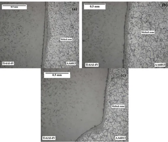
Figure 4. Ti/Al joint cross-sections with different laser positions, (a) interface line and (b) 0.3 mm toward Al alloy.
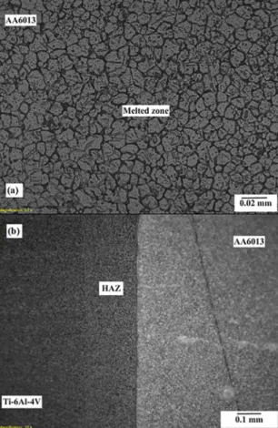
Figure 5. Microstructure of the joint (a) on the side of Al alloy and (b) the heat-affected zone (HAZ) on the side of Ti alloy.
and at 0.3 mm toward aluminium alloy, respectively). With the laser beam positioned in the interface line displaced at 0.3 mm toward aluminium alloy (Figure 4-b), the titanium alloy did not melt. In this case, the melted aluminium alloy wets the joining interface, triggering the joining of dissimilar metals24. The non-fusion of titanium alloy along the process restricts the thickness of brittle phases. On the other hand, when the laser beam was positioned in the interface line (Figure 4-a), both the titanium and aluminium alloy were melted. According to Majumdar et al.11, a mixed fusion
zone composed of TiAl3, TiAl and Ti3Al is generated, which deteriorates the mechanical properties of the junction.
Similarly, to the observed in previous work14, the fusion
zone of aluminium alloy exhibits a fine cellular dendritic solidification structure with many equiaxial grains in the weld centerline (Figure 5-a). Figure 5-b shows the heat-affected zone (HAZ) adjacent to the interface of titanium alloy side.
While the titanium alloy has not been melt, with the laser beam was positioned at 0.3 toward aluminium alloy, the
thermal cycle of the process modifies the microstructure of
the region. Song et al.21 have associated these changes to
an increase in volume fraction of α phase and a decrease in β phase when compared with titanium alloy base metal.
Figure 6 exhibits the interfacial microstructure of three
zones of the joint transverse section. The reaction layer can
be seen with non-uniform thickness along the transverse section. In previous works1,8, this reaction layer has been
characterized as zones with club-shaped and cellular/
serration-shaped morphologies.
3.3 Influence of silicon film on the microstructure
of joining interface
Studies have shown that the formation of brittle phases in the joining interface can be restricted by introducing silicon in this region3,13. In the present study, silicon was introduced in joining interface for its deposition on titanium alloy, by
means of the magnetron sputtering technique.
Figure 7 presents the transverse section of the joining
interface with silicon film on titanium alloy, deposited for 1
and 2 hours (Figures 7-a and 7-b, respectively), comparing with the aluminium and titanium joining without silicon
(Figure 7-c). There was a significant variation on compound layer thickness with the introduction of silicon film in this
region. Though the distribution of the layer thickness varies along the transverse section (Figure 6) the layer is thinner when compared to one formed in the joining without silicon introduction. This aspect may be associated with a lower
diffusion rate of the titanium atoms toward the aluminium
Figure 6. Magnified micrographs of the fusion zone interfacial microstructure, showing the (a) top, (b) middle, and (c) bottom region.
Table 2. Composition and phase of various regions from Fig.8-c. Point in
Fig.5-a Ti/at.% Al/at.% Possible Phase
P1 47.7 52.2 TiAl
P2 27.1 72.9 TiAl3
P3 26.2 73.7 TiAl3
P4 26.7 76.3 TiAl3
Figure 8. Distribution profile of Ti, Al and Si elements in the joining interface, comparing the effect of the silicon film deposited during (a) 1 hour and (b) 2 hours on Ti alloy, comparing with (c) a dissimilar joint without silicon film.
Figure 9. Ti-Al binary phase diagram22.
titanium and aluminium atoms near the joining interface during the process3.
The distribution profiles of the Ti, Al and Si elements at dissimilar joining with silicon film deposited on titanium
alloy for 1 and 2 hours are presented in the Figures 8-a and 8-b, respectively, in comparison with a condition without
silicon introduction (Figure 8-c). A significant decrease of the titanium diffusion width to aluminium alloy is observed
with the introduction silicon in the joining interface. The results are in agreement with the obtained in the microscopy analysis of this region (Figure 7). Moreover, the silicon
deposition time influenced the layer thickness formed
after joint process. A thin layer is formed with the silicon introduction, in the order of 3 µm, if compared to joint
process without silicon, up to five times thicker. Table 2 summarizes the phase compositions in different points of
the curve (Figure 8-c), denoted by P1-P4. Based on the Al-Si binary phase diagram (Figure 925) the possible phases of
each some zones are estimated. It is observed a continuous layer between P2 and P4 zones, near the interface region and
4. Conclusions
The experimental results reported in this work show the
influence of silicon introduction on the dissimilar joining
process as to the extension of the compound layer thickness. It was concluded that:
• When the laser beam was positioned near the interface area (0.3 mm toward aluminium alloy), the melted aluminium wet the titanium alloy, generating the joining interface with the more restricted compound layer.
• A decrease in the compound layer thickness has been observed with the silicon introduction in the joining interface, reaching the mean value of 3 µm,
i.e., up to five times thinner if compared to joining
with no silicon along the joining process. • The main phases observed in the joining interface
were TiAl and TiAl3. Further studies should associate
the influence of compound layer thickness and its
composition in the joint fracture behavior.
5. Acknowledgments
The author ACO thanks for financial support to FAPESP
(process number 2015/18235-0).
6. References
1. Vaidya WV, Horstmann M, Ventzke V, Petrovski B, Koçak M, Kocik R, et al. Improving interfacial properties of a laser beam welded dissimilar joint of aluminium AA6056 and titanium Ti6Al4V for aeronautical applications. Journal of Materials
Science. 2010;45(22):6242-6254.
2. von der Haar C, Engelbrecht L, Meier O, Ostendorf A, Haferkamp H. Tailored hybrid blank production-New joining concepts using different solders. Journal of Laser Applications. 2008;20(4):224-229.
3. Chen S, Li L, Chen Y, Liu D. Si diffusion behavior during laser welding-brazing of Al alloy and Ti alloy with Al-12Si filler wire. Transactions of Nonferrous Metals Society of China. 2010;20(1):64-70.
4. Tušek J, Kampuš Z, Suban M. Welding of tailored blanks of different materials. Journal of Materials Processing Technology. 2001;119(1-3):180-184.
5. Vaidya WV, Horstmann M, Ventzke V, Petrovski B, Koçak M, Tempus G. Structure-property investigations on a laser beam welded dissimilar joint of aluminium AA6056 and titanium Ti6Al4V for aeronautical applications Part I: Local gradients in microstructure, hardness and strength. Materialwissenschaft
und Werkstofftechnik. 2009;40(8):623-633.
6. Liedl G, Kratky A, Mayr M, Saliger A. Laser assisted joining of dissimilar materials. In: Proceedings of
IQCMEA-ICF-Processing, Performance and Failure Analysis of Engineering Materials; 2011 Nov 14-17; Luxor, Egypt. p. 22-31.
7. Luo JG, Acoff VL. Interfacial reactions of titanium and aluminum during diffusion welding. Welding Research. 2000;79(9):239s-243s. 8. Morizono Y, Fukuyama T, Matsuda M, Tsurekawa S. Liquid-Solid Reactions in Aluminum-Coated Titanium Substrate Fabricated by Using Explosive Energy. Materials Transactions. 2011;52(12):2178-2183.
9. Kimura M, Nakamura S, Kusaka M, Seo K, Fuji A. Mechanical properties of friction welded joint between Ti-6Al-4V alloy and Al-Mg alloy (AA5052). Science and Technology of Welding
and Joining. 2005;10(6):666-672.
10. Kattner UR, Lin JC, Chang YA. Thermodynamic Assessment and Calculation of the Ti-Al System. Metallurgical Transactions A. 1992;23(8):2081-2090.
11. Chen Y, Chen S, Li L. Influence of interfacial reaction layer morphologies on crack initiation and propagation in Ti/Al joint by laser welding-brazing. Materials & Design. 2010;31(1):227-233.
12. Naeem M, Jessett R, Withers K. Welding of dissimilar materials with 1kW fiber laser. Available from: < http://www.spilasers.com/ wp-content/uploads/2015/12/WEBSITE_WHITE_PAPER_-_ WELDING_OF_DISSIMILAR_MATERIALS_WITH_1KW_ FIBER_LASER.pdf>. Access in: 19/10/2017.
13. Schubert E, Klassen M, Zerner I, Walz C, Sepold G. Light-weight structures produced by laser beam joining for future applications in automobile and aerospace industry. Journal of
Materials Processing Technology. 2001;115(1):2-8.
14. Majumdar B, Galun R, Weisheit A, Mordike BL. Formation of a crack-free joint between Ti alloy and Al alloy by using a high-power CO2 laser. Journal of Materials Science. 1997;32(23):6191-6200.
15. Sohn HW, Bong HH, Hong SH. Microstructure and bonding mechanism of Al/Ti bonded joint using Al-10Si-1Mg filler metal.
Materials Science and Engineering: A. 2003;355(1-2):231-240.
16. Takemoto T, Okamoto I. Intermetallic compounds formed during brazing of titanium with aluminium filler metals. Journal of Materials Science. 1988;23(4):1301-1308.
17. Kim J, Lee K, Yang S. Wear-corrosion performance of Si-DLC coatings on Ti-6Al-4V substrate. Journal of Biomedical
Materials Research Part A. 2008;86A(1):41-47.
18. Capote G, Bonetti LF, Santos LV, Corat EJ, Trava-Airoldi JV. Influência da intercamada de silício amorfo na tensão total e na aderência de filmes de DLC em substratos de Ti6Al4V. Revista Brasileira de Aplicações de Vácuo. 2006;25(1):5-10.
19. Gomez-Veja JM, Hozumi A, Saiz E, Tomsia AP, Sugimura H, Tokai O. Bioactive glass-mesoporous sílica coatings on Ti6Al4V through enameling and triblock-copolymer-templated sol-gel processing. Journal of Biomedical Materials Research Part A. 2001;56(3):382-389.
20. Ruska WS. Microelectronic Processing: An Introduction to the
Manufacture of Integrated Circuits. New York: McGraw-Hill; 1997.
21. Reinig P, Fenske F, Fuhs W, Selle B. Crystalline silicon films grown by pulsed dc magnetron sputtering. Journal of
22. Oliveira AC, Siqueira RHM, Riva R, Lima MSF. One-sided laser beam welding of autogenous T-joints for 6013-T4 aluminium alloy. Materials & Design. 2015;65:726-736.
23. Oliveira AC, Riva R, Athanazio NMA. Yb:fiber laser joining of Ti-6Al-4V and AA6013 dissimilar metals. In: Proceeding of
Lasers in Manufacturing Conference; 2015 Jun 22-25; Munich, Germany.
24. Song Z, Nakata K, Wu A, Liao J. Interfacial microstructure and mechanical property of Ti6Al4V/A6061 dissimilar joint by direct laser brazing without filler metal and groove. Materials Science and Engineering: A. 2013;560:111-120.