Abstract— Laser Metal Deposition (LMD) is an additive manufacturing technique that produces parts layer by layer directly from the Computer Aided Design (CAD) file. Highly customized parts with complex shapes such as medical implants can well be manufactured using the LMD process. LMD has been used to produce a wide range of patient specific (customized) parts. Porous parts are of particular importance as medical implants because they can potentially aid the healing process and proper integration of the implant with the body tissues. In this research porous samples of titanium alloy (Ti6Al4V) were produced using the LMD process. Spherical shaped Ti6Al4V powder of particle size ranging between 150 to 200 µm was used. The effect of laser power and scanning speed on the shape, size and degree of porosity of the deposited tracks was investigated. The results showed that as the laser power was increased and the scanning speed decreased, the degree of porosity was reduced. The size of the porosity was also found to reduce as the laser power was increased.
Keywords— Laser Metal Deposition, Medical implants, Porosity, Processing parameters, Titanium alloy.
I. INTRODUCTION
aser Metal Deposition (LMD) is an additive m manufacturing technology, also known as solid freeform
fabrication that can be used to manufacture solid components directly from the Computer Aided Design (CAD) file [1, 2]. During the LMD process, powder is fed into the melt pool created by the laser beam on the surface
Manuscript received December 27, 2013; revised January 19, 2014. This work was supported by the Rental Pool Grant of the National Laser Centre -Council of Scientific and Industrial Research (NLC-CSIR), Pretoria, South Africa and The Schlumberger Foundation Faculty for the Future (FFTF).
Ms. Rasheedat M. Mahamood is a doctorate Student in the Department of Mechanical Engineering Science, University of Johannesburg, Auckland Park Campus, Johannesburg, South Africa, 2006. (e-mail: [email protected] or [email protected] )
Dr Esther T. Akinlabi is a Senior Lecturer in the Department of Mechanical Engineering Science, University of Johannesburg, Auckland Park Campus, Johannesburg, South Africa, 2006. (Phone: +2711-559-2137; email: [email protected]).
Prof Mukul Shukla is an Associate Professor in the Department of Mechanical Engineering Science, University of Johannesburg, Auckland Park Campus, Johannesburg, South Africa, 2006. (e-mail: [email protected]).
Prof Sisa Pityana is a Research Scientist in the National Laser Centre of Council for Scientific and Industrial Research (CSIR), Pretoria, South Africa. (E-mail: [email protected].)
of the substrate. The powder is delivered through an integrated powder delivery system. The heat generated by the melt pool as well as the laser beam causes the powder to melt and bound with the substrate. Upon solidification of the melt pool, a solid track of the deposited material is left on the laser path. The process is repeated layer upon layer until the building process is completed.
LMD process has a number of application areas which includes the production of prototypes, functional parts, medical implants and functionally graded materials [3]. It is also used in the repair of high valued components [4]. LMD process is particularly attractive for the fabrication of titanium medical implants because titanium is a difficult to machine material using traditional manufacturing methods such as milling and turning. Titanium and its alloys are more difficult to machine and uneconomical when the part to be made is complex and highly customized as is the case with medical implants [5, 6]. The chemical properties of Titanium make the tool to fail prematurely during cutting operation as a result of galling, which is the tearing of cutting tool as a result of friction and adhesion of the cutting tool to the material being cut. LMD like any additive manufacturing process produces parts by adding materials layer by layer as against material removal in traditional manufacturing processes. This will result in reduced time of production and less material wastage which helps to reduce the buy-to-fly-ratio in the production of aerospace parts [7]. The processing parameters in LMD process are very important, as they influence the properties (such as porosity and microstructure) of the part produced. Porosity in laser metal deposited parts is being seen as a defect in general in most applications [8] but it has been reported to be of great importance in healing process as well as proper integration of medical implants and body tissues in case of implants [9,10]. Ti6Al4V is an important titanium alloy used as medical implants because of its superior corrosion resistance properties and biocompatibility. Despite these exciting properties, the modulus of elasticity of titanium is higher than that of human bone. This higher modulus of elasticity in titanium leads to mismatch in titanium implant and the host bone. The modulus of elasticity of titanium can be reduced and made to be close to human bone by introducing porosity in the bulk material [11-13]. different types of porous titanium alloy have been produced using different methods [14-17]. The advantage of using additive manufacturing method to produce implant cannot be over emphasized because it is complex and highly customized. A number of porous titanium alloys has been produced in the literature using additive manufacturing method [18, 19]. Xiong et al [19] studied the feasibility of using 3d- printing to fabricate porous titanium implant. The study revealed that
Characterizing the Effect of Processing
Parameters on the Porosity of Laser Deposited
Titanium Alloy Powder
Rasheedat M. Mahamood, Esther T. Akinlabi, Mukul Shukla, Sisa Pityana
3d printing can be used to produce a porous implant with property close to those of human bones. Most of the porous medical implants produced in the literature are designed porosity [14-19]. That is, they are produced in such a way the part is porous. For example the way the porous part was produced in d was such that the layers are arranged in such a way that porosity is left on the path of laser. The problems with this type of porous implants are that, the shape of the pore created is of irregular geometry which is of high stress concentration factor [20]. This results in premature failure of the implant [20-23].
Processing parameters in LMD process has been shown to affect properties as well as porosity of deposited part [24]. In this study, the effect of laser power and scanning speed on the percentage porosity and average size of porosity of laser deposited Ti6Al4V was investigated. Lowering the scanning speed, lowers the percentage porosity and the average pore size. Also, it was found that increasing the laser power results in decreased percentage porosity but on the other hand resulted in increased pore size and spherical pores are produced at all process parameters.
II. MATERIALSANDMETHODS
2.1 Materials
The materials used in this study comprise of gas atomized Ti6Al4V powder and 5 mm thick 72 mm x 72 mm hot rolled Ti6Al4V plate. The powder particle size distribution ranged between 150-200µm. Prior to the deposition process, the substrate was sandblasted, washed and degreased using acetone in order to aid the absorption of the laser beam. Argon gas was used as the carrier gas for the powder as well as for shielding of the deposit to prevent oxidation.
2.2 Laser Metal Deposition Process
The LMD process was achieved using a Kuka robot carrying a 4 kW Nd-YAG laser and coaxial powder nozzle available at the Council of Scientific and Industrial Research (CSIR) National Laser Centre (NLC). The laser beam diameter was maintained at a 2 mm at a focal distance of 195 mm. Titanium is highly susceptible to oxidation at high temperature. To prevent oxidation during the deposition process, a shielding mechanism was improvised using plastic wrapping. The glove box (shielding mechanism) was filled with argon gas to maintain the oxygen level below 10 ppm. During the LMD process, the laser beam is focused on a particular spot on the substrate. The heat generated by the beam causes a melt pool to be created on the substrate. The powder is then delivered into the melt pool through the powder delivery system and melted. Upon solidification of the melt pool, a solid track is left on the path of the laser beam. The schematic diagram of the laser metal deposition process is shown in Figure 1. The powder flow rate and the gas flow rate were maintained at constant values of 1.44 g/min and 2 l/min respectively. The laser power of 400 and 800 W were used in this study. The scanning speed was varied between 0.005 and 0.2 m/s. The processing parameters used in this investigation are presented in Table 1. A single track was produced at each processing parameter
Figure 1. Schematic of the laser metal deposition process (adapted from [25])
Table 1. Processing Parameters settings Sample
Designation
Laser Power LP (W)
Scanning speed SS (m/s)
A 400 0.2
B 400 0.1
C 400 0.01
D 400 0.005
E 800 0.2
F 800 0.1
G 800 0.01
H 800 0.005
2.3 Material Characterization
After the deposition process, the samples were sectioned along the transverse direction for porosity analysis and microstructural studies. The cut samples were mounted in resin, ground and polished according to the standard metallographic preparation of titanium alloys [26]. Porosity analysis was performed using the optical microscope equipped with ANALYSIS Docu image processing software to establish the percentage of porosity. The average size of the pores was also measured by measuring the pore sizes at five different areas and the average results are reported.
.
III. RESULTS AND DISCUSSION
Figure 2. The photograph of the laser metal deposited Ti6Al4V
(a)
(b)
Figure 3. (a) Micrograph of Ti6Al4V substrate and (b) morphology of Ti6Al4V powder [27]
The percentage porosity in the deposits was measured at three different points on each sample and the averages of the percentage porosity are reported. Also, the average pore sizes were measured at five different points on each sample and the average pore sizes are reported. Table 2 presents the average percentage porosity and the average pore sizes of the samples. The bar chart of the percentage porosity is shown in Figure 4.
Table 2. Average percentage porosity and pore sizes of different samples
Sample Designation
Average porosity (%)
Average pore size (µm)
A 19.28 12.84
B 11.15 10.05
C 5.14 6.11
D 1.28 1.55
E 8.53 84.11
F 3.98 78.67
G 0.90 7.31
H No porosity -
Figure 4. Variation of average porosity and pore size for different samples.
The micrograph of a typical sample at a laser power of 400 W and the scanning speed of 0.1 m/s showing the porosities is shown in Figure 5a and that of the sample at a laser power of 800 W and scanning speed of 0.1 m/s is shown in Figure 5b.
(b)
Figure 5. Micrograph of samples at (a) 400 W laser power and 0.1 m/s scanning speed (Sample B) and (b) 800 W laser power and 0.1 m/s scanning speed (Sample F)
The porosity in the samples can be produced as a result of unmelted powder particles or as a result of gas entrapment in the melt pool that results in a blow-hole kind of porosity. Porosity resulting from unmelted powder particles is often smaller than those resulting from gas entrapment because the pore size resulting from unmelted powder is limited by the original particle size. The gas entrapment porosity depends on the turbulence in the melt pool during the deposition process and it can become very large as it becomes easy for two or more gasses to marge together during the solidification process. The shapes of the pores are mostly spherical in both cases. It can be observed from Figure 4 and Table 3 that as the laser power was increased from 400 W to 800 W, the average porosity was significantly reduced from about 19 % to 8.5 %. The reason for this behaviour can be attributed to the fact that, at lower laser power (400 W), the available power or energy for melting the surface of the substrate as well as the deposited powder was not sufficient. The available power did not properly melt the deposited powder and the unmelted powder was later removed during sample preparation resulting in porosity as shown in Figure 4a.
It was found that when the laser power was increased to 800 W, the higher power was made available for melting the powder, thereby reducing the unmelted powder particles. On the other hand, the average pore size was found to increase drastically as the laser power was increased. The porosity at higher laser power could be due to gas entrapment in the melt pool. The entrapped gas was not allowed to escape during solidification at high scanning speed because of the rapid solidification process (see Figure 4b). It can be seen that as the scanning speed was decreased, the average porosity and the average pore sizes also decreased. The reason for this is that at lower laser power, as the scanning speed was reduced, the laser material interaction time increased and more powder was melted. The increase in laser material interaction time resulted in a decrease in the degree of porosity. Also, at higher laser power, as the scanning speed was reduced, the solidification process became slow thereby allowing most of the gasses in the melt pool to escape before the solidification process was completed, and thereby reducing the degree of porosity. The porosity at lower laser power is mainly due to insufficient
melting of the powder particles and those at higher laser power was mostly due to gas entrapment which makes the pore sizes more larger at higher laser power.
Typical micrographs of the samples taken during the porosity analysis are shown in Figure 6. The green coloured areas represent the pores. The microstructure of the sample in Figure 6a is characterized by martensitic microstructure especially the microstructure surrounding the pores. This further confirms that the solidification of the sample was rapid and resulted in martensite formation. Comparing Figure 6b to Figure 6a, it can be seen that the pores are smaller in Figure 6b and the smaller pore sizes can be attributed to porosity resulting from the unmelted powder particles.
(a)
(b)
Figure 6 Micrograph of samples at (a) 800 W laser power and 0.1 m/s scanning speed (Sample F) (b) 400 W laser power and 0.1 m/s scanning speed (Sample B)
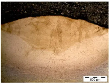
At the higher laser power of 800 W, as the scanning speed was further reduced to 0.005 m/s, no porosity was observed in the sample as shown in Figure 7.
This was because, the laser material interaction time was sufficiently large for all the powder particles to be completely melted and there was sufficient time for all the gasses in the melt pool to escape before solidification was completed. These factors resulted in a fully dense and porosity free deposit.
IV CONCLUSSION
Porosity is seen as a defect in most engineering applications but can be an advantage in medical implants. The effect of laser power and scanning speed on the degree of porosity and size of porosity was investigated in this study. The study revealed that, the lower the scanning speed, the lower is the degree of porosity and smaller are the pore sizes. Also, higher the laser power, lower is the degree of porosity. The pore sizes were found to increase significantly as the laser power was increased which was attributed to gas entrapment in the melt pool. The pore shapes are mostly spherical as against irregular shapes produced using other methods stated earlier. The irregular pore shapes are detrimental to life of the implant. This shows that a better porous implant can be made by controlling the processing parameters in LMD process. This study will help in selecting the proper processing parameters for manufacturing of porous implants depending on the degree of porosity desired as well as the pore sizes desired.
Acknowledgments
This work is supported by the Rental Pool Grant of the National Laser Centre - Council of Scientific and Industrial Research (NLC-CSIR), Pretoria South Africa and The Schlumberger Foundation Faculty for the Future (FFTF).
REFERENCES
[1] Choi, J. (2002). Process and Properties Control in Laser Aided Direct Metal/Materials Deposition Process. Proceedings of IMECE, New Orleans, Louisiana, November 17–22, –9.
[2] Wu, X.H., Jing, L., Mei, J.F., Mitchell, C., Goodwin, P.S. and Voice W. (2004). Microstructures of laser-deposited Ti–6Al–4V. Mater Des, 25, PP. 137–44.
[3] Mahamood, R. M., Akinlabi, E. T., Shukla M. and Pityana, S. (2012). Functionally Graded Material: An overview, Lecture Note in
Engineering, WCE 2012, July 4-6,2012, London, United Kingdom,
3, 1593-1597.
[4] Pinkerton, A. J., Wang W. and Li, L. (2008). Component repair using laser direct metal deposition. Proc. IMechE Vol. 222 Part B: J. Engineering Manufacture, 8270-836.
[5] Watanabe, I., Kiyosue, S., Ohkubo, C., Aoki, T. and Okabe, T. (2002). Machinability of cast commercial titanium alloys. J Biomed Mater Res. 63(6), 760-4.
[6] Arrazola, P. J., Garay, A., Iriarte, L.-M., Armendia, M., Marya, S. and Le Maître, F. (2009). Machinability of titanium alloys (Ti6Al4V and Ti555.3), J. Mater. Process. Technol. 209(5), 2223-2230.
[7] Hillier, C. (2010). Powder-Cored Tubular Wire Development for Electron Beam Freeform Fabrication. Department of Metallurgical and Materials Engineering, Colorado School of Mines, Golden. [8] Ng, G. K. L., Jarfors, A. E. W., Bi, G. and Zheng, H. Y. (2009).
Porosity formation and gas bubble retention in laser metal deposition. Applied Physics A, 97, 641–649.
[9] Naumann, A., Ehrmantraut, S., Willnecker, V., Menger, M. D., Schick, B. and Laschke, M. W. (2011). Ear reconstruction using
porous polyethylene implants. Effect of cortisone on edema reduction and healing process]. HNO. 59(3), 268-73.
[10] Motomiya, M., Ito, M., Takahata, M., Kadoya, K., Irie, K., Abumi, K. and Minami, A. (2007). Effect of Hydroxyapatite porous characteristics on healing outcomes in rabbit poster lateral spinal fusion model, Eur Spine J. , (12), 2215-24.
[11] Schiefer H, Bram M, Buchkremer HP, Stöver D. (2009). Mechanical examinations on dental implants with porous titanium coating. J Mater Sci Mater, 20, 1763-1770.
[12] Krishna, B.V., Bose, S. and Bandyopadhyay, A. (2007). Low stiffness porous Ti structures for load-bearing implants. Acta Biomater, 3, 997-1006.
[13] Chen Y. J., Feng B., Zhu Y. P., Weng J., Wang J. X., Lu X. (2009). Fabrication of porous titanium implants with biomechanical compatibility. Mater Lett., 63, 2659-2661.
[14] Li, J. P., S. H., and Van Blitterswijk, C. A. (2006). Cancellous Bone from Porous TI6Al4V by Multiple Coating Technique. Journal of Materials Science: Materials in Medicine, 17, 179-185.
[15] Krishna, B.V., Xue, W., Bose, S. and Bandyopadhyay, A. (2008). Engineered Porous Metals for Implants, Journal of Materials. TMS Springer Sciences & Business Media, LLC New York, NY 10013. [16] Wen, C.E., Mabuchi, M., Yamada, Y., Shimojima, K., Chino, Y. and
Asahina, T. (2001). Processing of biocompatible porous Ti and Mg. Scripta Materialia, 45, 1147-1153.
[17] Oh, I. H, Nomura, N., Masahashi, N. and Hanada, S. (2003). Mechanical properties of porous titanium compacts prepared by powder sintering. Scripta Materialia, 49, 1197-1202.
[18] Justin, D. F. and Stucker, B. E. (2009). Laser based metal deposition (LBMD) of implant structures, US Patent US7632575 B2.
[19] Xiong, Y., Qian C. and Sun, J. (2012). Fabrication of porous titanium implants by three-dimensional printing and sintering at different temperatures, Dental Materials Journal, 31(5), 815–820.
[20] Yue, S., Pilliar, R. M., and Weatherly, G. C. (1984). The fatigue strength of porous-coated Ti–6% Al–4%V implant alloy. J Biomed Mater Res, 18, 1043–58.
[21] Kohn, D. H. and Ducheyne, P. (1990). A parametric study of the factors affecting the fatigue strength of porous coated Ti–6A1–4V implant alloy. J Biomed Mater Res, 24, 1483–501.
[22] Crowninshield, R. D. (1986). Mechanical properties of porous metal total hip prostheses. Instr Course Lect., 35,144–8.
[23] Manley, M. T., Kotza, G., Stern, L. S. and Wilde, A. (1987). Effects of repetitive loading on the integrity of porous coatings. Clin Orthop Relat Res., 293–302.
[24] Imran, M. K., Masood, S., Brandt, M., Bhattacharya S. and Mazumder, J. (2011). Parametric Investigation of Diode and CO2 Laser in Direct Metal Deposition of H13 Tool Steel on Copper Substrate, World Academy of Science, Engineering and Technology, 55, 437-442
[25] Mahamood, R. M., Akinlabi, E. T., Shukla M. and Pityana, S. (2012). Effect of Laser Power on Material Efficiency, Layer Height and Width of Laser Metal Deposited Ti6Al4V" World Congress of Engineering and Computer Science, San Francisco, 24-26 October 2012. 1433-1438.
[26] Taylor, B. and Weidmann, E. (2008). Metallographic preparation of titanium, Struers 541 application notes,
http://www.struers.com/resources/elements/12/104827/
542Application_Note_Titanium_English.pdf (Accessed 24.04.12). [27] Mahamood, R. M., Akinlabi, E. T., Shukla M. and Pityana, S. (2013).
![Figure 1. Schematic of the laser metal deposition process (adapted from [25])](https://thumb-eu.123doks.com/thumbv2/123dok_br/18341924.352083/2.892.457.821.73.336/figure-schematic-laser-metal-deposition-process-adapted.webp)