497 Adriano Toledo Silva1
Arlene Maria Cunha Sarmanho2
http://orcid.org/0000-0001-6900-8551 Gabriel Vieira Nunes3
https://orcid.org/0000-0002-9222-5308 Daniel José Rocha Pereira4
https://orcid.org/0000-0002-7291-5598 Luiz Henrique de Almeida Neiva5
http://orcid.org/0000-0003-3397-4293
1Engenheiro Civil, MSc, Universidade Federal de Ouro
Preto – UFOP, Escola de Minas, Departamento de Engenharia Civil, Ouro Preto – Minas Gerais - Brasil. [email protected]
2
Professora-Titular, Universidade Federal de Ouro Preto – UFOP, Escola de Minas, Departamento de Engenharia Civil, Ouro Preto – Minas Gerais - Brasil. [email protected]
3Professor, Instituto Federal de Minas Gerais – IFMG,
Departamento de Edificações, Congonhas - Minas Gerais – Brasil.
4Doutorando, Universidade Federal de Ouro
Preto – UFOP, Escola de Minas, Departamento de Engenharia Civil, Ouro Preto – Minas Gerais - Brasil. [email protected]
5Doutorando, Universidade Federal de Ouro
Preto – UFOP, Escola de Minas, Departamento de Engenharia Civil, Ouro Preto – Minas Gerais - Brasil. [email protected]
Cold formed
steel semi rigid joints
Abstract
This article presents a theoretical and numerical study of an innovative joint us-ing cold-formed steel sections. The motivation for the study of this connection is the ease of manufacturing and assembly that it provides. The profiles are made of cold-formed lipped channel sections, which are welded to form closed built-up sections on the columns and open built-up lipped sections to the beams. The beams use endplates connected by bolts (threaded bars) to the columns. The study evaluates the connection’s initial stiffness of 19 models, where the following parameters were varied: the thickness of the profiles and endplates, the height of the column sections and the diameter of the bolts. A theoretical and a numerical study were developed: the numerical study was performed using finite elements through the commercial software ANSYS, whereas the theoretical study was made based on the component method, prescribed by Eu-rocode 3, that does not include the design of the connection analyzed herein. Thus, aiming to enable the design of joints composed of cold-formed lipped channel sections, the analysis results were compared and an adjustment coefficient, proportional to the slenderness of the column’s plates, was proposed. The coefficient was introduced to the stiffness component that represents the column web in compression in the mechanical model. The ratio between the coefficients’ numerical and theoretical values presented a maximum variation of 11%, which was considered satisfactory.
Keywords: cold-formed, numerical analysis, semi-rigid joints.
http://dx.doi.org/10.1590/0370-44672017710121
Civil Engineering
Engenharia Civil
1. Introduction
The beam-column connections of steel profiles are commonly con-sidered as rigid or pinned. According to Eurocode 3 (2010), pinned joints should be capable of transmitting the internal forces, without developing
significant moments, which might adversely affect the members or the structure as a whole. On the other hand, joints classified as rigid may be assumed to have sufficient rotational stiffness to justify analysis based on
498
and have partial transmission capacity of the bending moment and rotation. These joints are called semi-rigid and its use should be an economic solution for structural designs.
The first study analyzing rota-tional stiffness was developed by Wil-son and Moore (1917). Since then, nu-merous works addressed the subject, contributing to the development of normative prescriptions, either using the similarity of the beam-to-column endplate joints with the behavior of T-stub connections, or based on finite elements analysis. Krishnamurthy (1978) recommended a design method for endplate connections, and
Ri-beiro et al. (1998) performed several
experimental tests and analyzed the influence of the endplate thickness and the bolt diameter in these joints, using Krishnamurthy’s
recommenda-tions. Lima et al. (2004) and Silva
et al. (2004) studied the influence
of axial forces on beam-to-column joints, showing that the presence of
axial force on the beam significantly modified the joint response.
Garifullin et al. (2017)
evalu-ated the existing calculation approach for the initial rotational stiffness of welded rectangular hollow sections T joints. Based on experimental results, the authors proposed an improved equation for the component ‘main member flange in bending’. Zhao
et al. (2017) presented a
mechani-cal model based on the component method to predict the initial rotational stiffness of boltless connections in cold-formed steel storage racks. The comparisons between the numerical and experimental results showed that the mechanical model can properly evaluate the initial rotational stiffness of the studied connections.
Further-more, Bučmys et al. (2018) studied
cold-formed steel bolted gusset plate connections based on the component method approach. A three-spring mechanical model and a technique to calculate joint stiffness were
pre-sented. Based on the experimental and numerical results, the authors showed that the stiffness coefficients that are listed in Eurocode 3 part 1-8 could be applied to the studied joints.
Within this context, this ar-ticle analyzes the initial stiffness of an innovative joint composed by cold-formed steel sections, using the component method proposed in Eurocode 3 (2010). This analytical method evaluates the stiffness of some types of predefined connections that allow presenting the known moment-rotation behavior. In this work, the equations proposed by the Eurocode method received an adjustment coef-ficient proportional to the slenderness of the column’s plates to assimilate the difference in geometric characteristics of this new joint. The results of this new formulation were compared with finite element numerical models, developed in software the ANSYS 12.0 (2012). The results were considered satisfactory and will be presented in the next sections.
2. Numerical analysis
2.1 Geometric properties
The profiles used in the numerical and theoretical analyses are made of cold-formed lipped channel sections, which are
welded to form a closed built-up section on the columns and open built-up lipped section to the beams, which have welded
endplates. These plates are connected to the column through six bolts (threaded bars) and nuts, as shown in Figure 1.
Figure 1
Beam-column connection.
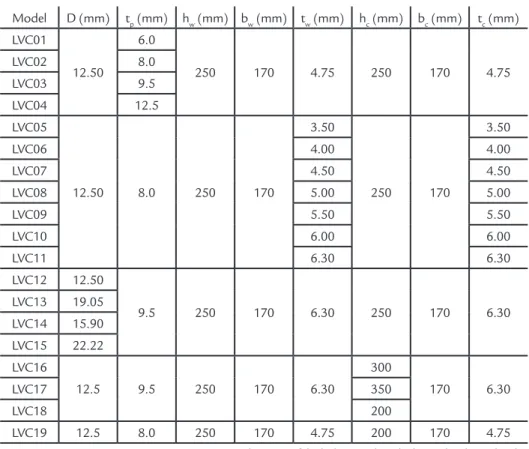
The study of the connection was performed through the variation of the geometry of the components. The mod-els considered are presented in Table 1.
The beam (tw), column (tc) and endplate (tp) thicknesses were varied, along with the height of the tubular columns (hc) and bolt diameters (D). These
499
Model D (mm) tp (mm) hw (mm) bw (mm) tw (mm) hc (mm) bc (mm) tc (mm) LVC01
12.50
6.0
250 170 4.75 250 170 4.75 LVC02 8.0
LVC03 9.5 LVC04 12.5 LVC05
12.50 8.0 250 170
3.50
250 170
3.50
LVC06 4.00 4.00
LVC07 4.50 4.50
LVC08 5.00 5.00
LVC09 5.50 5.50
LVC10 6.00 6.00
LVC11 6.30 6.30
LVC12 12.50
9.5 250 170 6.30 250 170 6.30 LVC13 19.05
LVC14 15.90 LVC15 22.22 LVC16
12.5 9.5 250 170 6.30
300
170 6.30
LVC17 350
LVC18 200
LVC19 12.5 8.0 250 170 4.75 200 170 4.75
D - diameter of the bolts; tp - plate thickness; hw - beam height;
bw - width of beam; tw - beam thickness; hc - column height; bc - width of column; tc - column thickness
Table 1 Connection components geometry.
2.2 Properties of materials
The numerical modeling used materials with the following mechani-cal properties: modulus of elasticity (E) equals to 205 GPa, Poisson
coef-ficient (υ) equals to 0.3, yield strength
equals to 250 MPa, equivalent to steel grade A36, for all elements. As in Maggi (2005), the tangent modulus (Et) used in this study is 10% of the longitudinal modulus of elasticity (E).
The material’s nonlinearity was con-sidered with a bilinear stress-strain diagram, which divides the elastic and plastic behavior into two straight-line segments.
2.3 Modeling method
The numerical models were per-formed through ANSYS (2012), a com-mercial software that uses the Ansys Parametric Design Language (APDL). This language uses text files where com-mands are entered to set the following: parameters that define the geometry, material types and elements, mesh, loads, and boundary conditions.
The shell element "SHELL181" was used on the beams and columns. In plates and bolts, the most suitable was the
volumetric element "SOLID95". Finally, to represent the geometric discontinuities between the components, the elements used were "TARGE170", "CONTA175" and "CONTA174", always used in pairs in the connection. The contact elements are used between:
• Bolt and endplate;
• Endplate and column flange; • Column stiffeners;
• Bolt and column.
The characteristics of the
men-tioned elements are: “SHELL181” – a plan element with four nodes with six degrees of freedom and translations in the x, y and z axes; “SOLID95” – a volumetric element with twenty nodes with translations in the x, y and z axes. The "CONTA174" is used when the base elements ("SOLID95") are volumetric and "CONTA175" are used with surface elements ("SHELL181"), both used with the target element “TARGE170”.
3. Theoretical analysis
3.1 Component method
The theoretical analysis was per-formed according to the component method, proposed by Eurocode 3 (2010). The component method is based on the
plastic distribution of tensile forces in the bolt-rows. This means that the force on any row is determined not only by its distance to the line of rotation of the
con-nection, but also by the geometry of each bolt-row. The coefficients are associated in series in the lines and later associations are performed in parallel between them.
3.2 Connection coeffificients
The coefficients used in the con-nection are presented herein and the calculation procedure proposed by the method of the components are
presented in Figure 2. The component method for the joint analyzed can be applied considering three coefficients:
the column web in compression (k2),
the endplate in bending (k5) and bolts
in tension (k10), as shown in the full
500
Figure 2
Rotational stiffness
calculation procedure.(a) Beam-to-column joint, (b) Mechanical model.
(a) (b)
The effective stiffness of the associated “springs” in series is calculated for each bolt-row by Equation 1:
Where ki,n represents the value of
the i-th coefficient in the n-th
bolt-row. The next step is to calculate the
equivalent stiffness, keq, of the
bolt-row, now associating in parallel, by Equation 2:
Where hn is the distance between the
bolt-row and the compression center; keff,n is the
equivalent stiffness of the associated line
in series and zeq is given by the Equation 3:
Finally, the rotational stiffness is determined by Equation 4:
Sj
E.z2
μ (k1
1+
1 k2+
1 keq)
Where E is the modulus of elasticity
of the steel; k1 and k2 are the stiffness
coefficients of components 1 and 2
respectively; z is the lever arm and μ is
the ratio of rigidities Sj, ini/ Sj obtained
through Equation 5:
if Mj, Sd
≤
23. Mj, Rd μ 1
if 2
3. Mj, Rd
≤
Mj, Sd≤
Mj, Rd μ1.5.Mj, Sd
Mj, Rd
2.7
(
)
=>
=>
Although the method presents 15 components, only 3 interfere in the initial
stiffness of the connection object of this
work: k2 - Column web in compression;
k5 – Endplate in bending and k10 – Bolts
in tension.
3.2.1 Coefficient k
2– Column web in compression
The stiffness coefficient for the non-stiffened column web in compression is given by Equation 6:
k2 0.7. beff,c, wc.tc hc
Where hc is the column height, and
bef f,c,wcis given by the expression beff,c,wc = tw+ 2√2 ap+ 5(tc+s)+ sp; where: tc
is the column web thickness; ; tw is the
beam web thickness; ap is the weld throat
between the flange of the beam and the
endplate; s is the weld throat in welding
profiles; and sp is the length obtained by
diffusion at 45° on the endplate.
3.2.2 Coefficient k
5– Endplate in bending
The stiffness coefficient for the non-stiffened endplate in bending
com-ponent, submitted to bending is similar to the previous coefficient and is given
by the Equation 7:
k5 0.9 .leff .tp
3
m3
(1)
(2)
(3)
(4)
(5)
(6)
(7)
keff,n 1
Σ 1
ki,n
keq Σ keff,n.hn zeq
zeq Σkeff ,n.hn
2
501
Where leff and m are geometric coefficients and tp is the endplate thickness.
3.2.3 Coefficient k
10– Bolts in tension
The stiffness coefficient relative to the bolts in tension is given by the Equation 8:
k10 1.6.
As Lb
Where Lb is the bolt elongation length (Equation 9) and As cross-section area of the bolt.
Lb hc+ 2tp
4. Results
4.1 Numerical results
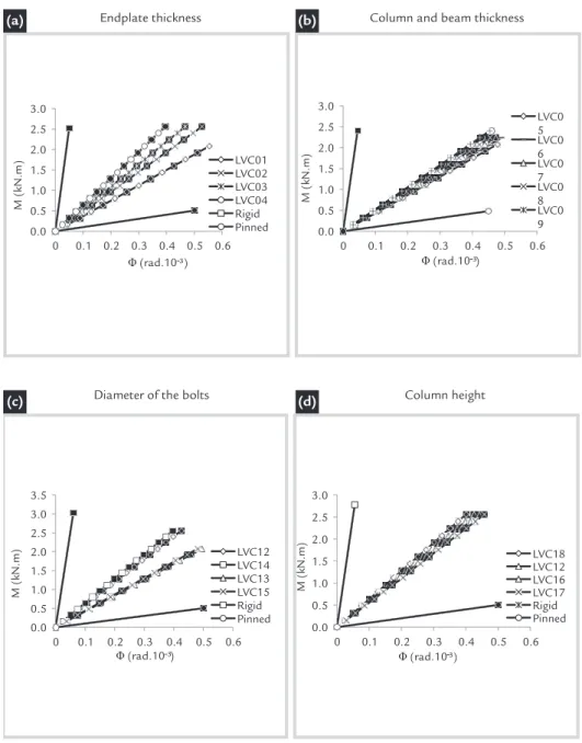
Considering the 19 models de-scribed in Table 1, four comparisons are made in Figure 3, that shows the con-nections’ Moment-Rotation behavior.
In Figure 3 (a), the endplate thickness is varied in the 4 models compared; in Figure 3 (b), the column and beam thicknesses are both varied in the 7
models analyzed, while in Figure 3 (c) the diameter of the bolts and in Figure 3 (d) the column height are the parameter that are altered.
(8) (9)
Figure 3 Variation of the initial stiffness of the models.
(a) (b)
(c) (d)
The deformed shapes of the joint are presented in Table 2, that shows the defor-mation of the 3 components that interfere
in the initial stiffness of the connection; column 1 shows the initial deformation at a stage where the bending moment
502
Table 2
Displacement vector
sum of the connection’s components (mm).
4.2 Coefficient adjustment proposition
Since Equation 6 does not represent
the k2 component, due to different tubular
profile buckling modes of an open built-up lipped section, it was necessary to add
a coefficient “Q”, obtained based on the
numerical analysis data. This coefficient, given by Equation 10, is proportional to the slender profile, which correlates
the profiles presented by the component method used by Eurocode 3 (2010), with formed lipped channel sections used in the present study.
Q 1
25.
c
tc h
√
Thus, the coefficient k2 is replaced by Equation 11, considering two column’s webs (2tc).
(10) (11)
c
tc h
√
k2 1
25. .
0.7. beff,c,wc.2tc hc
4.3 Evaluation of the initial stiffness of the connection
The multiplication of the coefficient
“Q” in the formulation of k2, and the
modi-fications presented, provided an equation very well estimated in the numerical analy-sis. Figure 4 shows the representative curve
of the theoretical and numerical results of LVC01 model, containing the curves with and without the consideration of the
coefficient “Q” and the limits of rigidity
proposed by Eurocode 3 (2010).
Finally, Table 3 shows the initial stiffness value for the theoretical and nu-merical results, the last column presents the ratio between the theoretical
503
Figure 4 Initial stiffness evaluation for the theoretical and numerical LVC01 model.
Model Sj.ini.teo (kN.m/rad) Sj.ini.num (kN.m/rad) Sj.ini.teo / Sj.ini.num LVC01 3.299.26 3.738.07 0.88 LVC02 4.605.94 4.844.72 0.95 LVC03 5.223.11 5.417.06 0.96 LVC04 6.324.99 6.475.70 0.98 LVC05 3.802.25 4.362.16 0.87 LVC06 4.081.14 4.559.29 0.90 LVC07 4.421.57 4.747.35 0.93 LVC08 4.770.02 4.926.91 0.97 LVC09 5.090.01 5.222.91 0.97 LVC10 5.408.68 5.210.87 1.04 LVC11 5.595.88 5.291.29 1.06 LVC12 6.552.11 6.018.20 1.09 LVC13 6.848.62 4.227.06 1.62 LVC14 6.670.88 6.448.29 1.03 LVC15 6.955.04 4.279.17 1.63 LVC16 5.710.66 5.786.66 0.99 LVC17 5.229.30 5.586.04 0.94 LVC18 7.100.68 6.379.74 1.11 LVC19 5.161.45 4.903.92 1.05 Sj.ini.teo - Theoretical Analysis Sj.ini.num- Numerical Analysis
Table 3 Ratio between theoretical and numerical results.
5. Discussion
From the data in Figure 3, it is pos-sible to notice that the endplate thickness is an important factor responsible for the connections’ stiffness behavior, mainly be-cause it can be subjected to the occurrence of bending, as shown in Table 2, that causes displacements in the beam. Likewise, the raise of the column and beam thicknesses increases connection rigidity, as shown in Figure 3 (b), due to higher values for the mo-ment of inertia that prevent greater bending effects in the column webs.
The diameter of the bolts was an-other determinant factor for the analysis,
considering that in two of the bolts lines, they were subjected to tension. In Figure 3 (b), it is observed that there was no direct relationship between the increase of the bolt diameter and the connections’ rigidity; in fact, the cases with higher diameter values presented a lower rigidity behavior, which can be explained by the fact that the higher diameter values provided less bending in the bolts located in the lower region of the connection, making the column web receive all of the load coming from the lower flange of the beam.
Even though the column height
varia-tion did not represent high values of disper-sion in the Moment-Rotation curves, as shown in Figure 3 (d), it is noticed that the raise of the height, that represents a higher value of slenderness (height/thickness), generates a lower value of rigidity, leading to the effect seen in the column web shown in Table 2.
To enable the design of the connection analyzed herein, from the numerical analy-sis data, a coefficient “Q” was proposed, and its incorporation in the component method provided close results to the numeri-cal values, as shown in Figure 4 and Table 3.
6. Conclusions
The general component method is used to calculate the stiffness coefficients of specific components and is limited by some criteria. This article presented
a connection between cold-formed sec-tions, and through the addition of some related coefficients, it was possible to use the mechanical model, used by Eurocode
3 (2010), in a connection outside the es-tablished limits.
The adjustment coefficient “Q”,
504
Received: 19 July 2017 - Accepted: 3 May 2018. column’s plates, was introduced to the
co-efficient k2 (the stiffness component of the
mechanical model for the non-stiffened column web in compression) and provided the ratio between numerical and
theoreti-cal coefficients with a maximum variation of 11%, which was considered satisfactory.
Even though the study herein pre-sented is limited to specific geometries of cold-formed lipped channel sections, the
results showed that the design of this type of connection with the consideration of its initial stiffness can be allowed, using the component method with the adjustment coefficient proposed.
Acknowledgments
The authors would like to thank UFOP, CAPES and CNPq for the financial
support received for the development of this research.
References
ANSYS Version 12.0. Theory Reference, ANSYS, Inc., 2012.
BUČCMYS, Ž., DANIŪNAS, A., JASPART, J., DEMONCEAU, J. A component
me-thod for cold-formed steel beam-to-column bolted gusset plate joints. Thin-Walled
Structures, v. 123, p. 520-527, 2018.
EUROCODE 3: Design of steel structures. Part 1-8: Design of joints, 2010.
GARIFULLIN, M., PAJUNEN, S., MELA, K., HEINISUO, M., HAVULA, J. Initial in-plane rotational stiffness of welded RHST joints with axial force in main
mem-ber. Journal of Constructional Steel Research, v. 139, p. 353-362, 2017.
LIMA, L. R. O. DE, VELLASCO, P. C. G. da S. , SILVA, L. A. P. S. da (.) AN-DRADE, S. A. L. de. Experimental evaluation of extended endplate
beam-to-co-lumn joints subjected to bending and axial force. Engineering Structures, Estados
Unidos, v. 46, n.7, p. 1-15, 2004.
KRISHNAMURTHY, N. A fresh look at bolted end-plate behaviour and design.
AISC Engineering Journal, v.15, 2nd Quarter, p. 39-49, April, 1978.
MAGGI, Y. I., GONÇALVES, R. M., LEON, R. T., RIBEIRO, L. F. L. Parametric
analysis of steel bolted endplate connections using finite element modeling. Journal
of Constructional Steel Research, v. 61, n.5, p. 689-708, 2005.
RIBEIRO, L. F. L., GONÇALVES, R. M., CASTIGLIONI, C. A. Beam-to-column
end plate connections - an experimental analysis. Journal of Constructional Steel
Research, Surrey. London, v. 46, p. 264-266, 1998.
SILVA, L. A. P. S. da, LIMA, L. R. O. DE , DE LIMA, L.R.O. , VELLASCO, P. C. G. da S. , ANDRADE, S. A. L. de (.) Behaviour of flush end-plate beam-to-column
joints under bending and axial force. Steel and Composite Structures. Coréia,
v. 4, n.2, p. 77-94, 2004.
WILSON W. M., MOORE, H. F. Tests to determine the rigidity of riveted joints in
steel structures. University of Illinois, 1917. (Bulletin n.104).
ZHAO, X., DAI, L., WANG, T., SIVAKUMARAN, K. S., CHEN, Y. A theoreti-cal model for the rotational stiffness of storage rack beam-to-upright connections.
Journal of Constructional Steel Research, v. 133, p. 269-281, 2017.