Bachelor of Science in Biomedical Engineering
Establishing a Framework for the development of
Multimodal Virtual Reality Interfaces with
Applicability in Education and Clinical Practice
Dissertation submitted in partial fulfillment of the requirements for the degree of Master inBiomedical Engineering
Adviser: Hugo Alexandre Ferreira, Assistant Professor,
Instituto de Biofísica e Engenharia Biomédica,
Faculdade de Ciências da Universidade de Lisboa
Examination Committee
Interfaces with Applicability in Education and Clinical Practice
Copyright © Filipe Miguel Sobreira Rodrigues, Faculty of Sciences and Technology, NOVA University of Lisbon
The Faculty of Sciences and Technology and the NOVA University of Lisbon have the right, perpetual and without geographical boundaries, to file and publish this dissertation through printed copies reproduced on paper or on digital form, or by any other means known or that may be invented, and to disseminate through scientific repositories and admit its copying and distribution for non-commercial, educational or research purposes, as long as credit is given to the author and editor.
First and foremost, I would like to thank my adviser and mentor Hugo Alexandre Ferreira, for welcoming me intoInstituto de Biofísica e Engenharia Biomédica(IBEB) and tirelessly accompanying me throughout this past academic year. Besides behooving my way of thinking in an almost uncanny way, his somewhat less than orthodox approach towards research and science in general greatly broadened my horizons and incited me to enroll in similar pursuits.
It cannot be left unsaid that this project would not have been the same without the financial aid that ensued from the partnership between IBEB and the Luso-Illyrian Insti-tute for Human Development (iLIDH) in the Museum of Universal Values (MUV) project, for which I am much obliged.
I would also like to take the opportunity to express my gratitude to Professor Hugo Gamboa, who was my co-adviser on all accounts but the official one. His readiness to
help me with both resources and guidance did not go unnoticed.
On the same train of thought, I am also obligated to acknowledge Professors Hugo Silva, Pedro Vieira and Ivo Costa, who collectively lent me their time, expertise and advice. If not for them, my previously virtually non-existent soldering skills would have seeped into this project and undermined it immensely.
My sincere appreciation for Filipe Silvestre, João Melo Costa and Rachel Freire who respectively aided me with all my 3D printing, textile design and pattern cutting needs. A huge thank you goes out to Kip Bunyea, Alex Colgan, Kate Mitchell and the whole of Leap Motion©’s team for all the support and coverage.
Last but definitely not least, I have to end by thanking all my friends and family for putting up with me even as I receded into a thesis-writing hermit. At this point I have pretty much used up all the fancy words in my vocabulary so I will just name you randomly: Mom (sorry about turning the living-room into a cellphone graveyard), Dad, Duarte Folgado, Miguel Aragão, João Valverde, Vasco Valverde, Gonçalo Sousa, José Maria Tanqueiro, Teresa Serradas Duarte, Renato Gomes, Pedro Rodrigues, Tiago Rodrigues, Cátia Cepeda, Marta Telhada, Carolina Ramalho, João Pedro Freitas, José Maria Freire, Francisco Dias Lopes and Nuno Torres.
doing."
The development of Virtual Reality (VR) and Augmented Reality (AR) content with multiple sources of both input and output has led to countless contributions in a great many number of fields, among which medicine and education.
Nevertheless, the actual process of integrating the existing VR/AR media and subse-quently setting it to purpose is yet a highly scattered and esoteric undertaking. Moreover, seldom do the architectures that derive from such ventures comprise haptic feedback in their implementation, which in turn deprives users from relying on one of the paramount aspects of human interaction, their sense of touch.
Determined to circumvent these issues, the present dissertation proposes a centralized albeit modularized framework that thus enables the conception of multimodal VR/AR applications in a novel and straightforward manner.
In order to accomplish this, the aforesaid framework makes use of a stereoscopic VR Head Mounted Display (HMD) from Oculus Rift©, a hand tracking controller from Leap Motion©, a custom-made VR mount that allows for the assemblage of the two preceding peripherals and a wearable device of our own design. The latter is a glove that encom-passes two core modules in its innings, one that is able to convey haptic feedback to its wearer and another that deals with the non-intrusive acquisition, processing and regis-tering of his/her Electrocardiogram (ECG), Electromyogram (EMG) and Electrodermal Activity (EDA). The software elements of the aforementioned features were all interfaced through Unity3D©, a powerful game engine whose popularity in academic and scientific endeavors is evermore increasing.
Upon completion of our system, it was time to substantiate our initial claim with thoroughly developed experiences that would attest to its worth. With this premise in mind, we devised a comprehensive repository of interfaces, amid which three merit special consideration: Brain Connectivity Leap (BCL), Ode to Passive Haptic Learning (PHL) and a Surgical Simulator.
A inclusão de múltiplas fontes de inputeoutput no desenvolvimento de conteúdo para Realidades Virtual (VR) e Aumentada (AR) tem culminado em inúmeras e valorosas contribuições em diversas áreas, entre as quais medicina e educação.
Não obstante, os processos envolvidos tanto no processo de integração dos meios de VR/AR actualmente existentes como no da sua subsequente aplicação, permanece uma tarefa algo dispersa e ainda esotérica. Ademais, a grande maioria das interfaces que resultam destes procedimentos continua a não incorporar uma componente defeedback
háptico na sua arquitectura, impossibilitando por conseguinte que os seus utilizadores possam fazer recurso daquele que é um dos aspectos preponderantes do esquema de interacção humana, o sentido do toque.
Com vista a lograr estas lacunas, a presente dissertação propõe uma plataforma cen-tralizada e ainda assim modularizada que possibilita a concepção de interfaces de VR/AR multimodais, naquela que na nossa óptica é uma abordagem inovadora e focalizada. Para o conseguir, a plataforma supra-referida emprega os óculos de VR Oculus Rift©, ao qual um controlador de captura de movimento da Leap Motion© se associa por intermédio de um suporte personalizado. Complementarmente, um equipamentowearablepor nós concebido está também incluído no sistema idealizado. Este último consiste numa luva que não só é capaz de transmitirfeedbacktáctil ao seu utilizador como ainda está apta a
ad-quirir, processar e registar os seus sinais Electrocardiográficos (ECG), Electromiográficos (EMG) e de Actividade Electrodérmica (EDA) de forma não invasiva. Os elementos ante-riormente referidos foram interfaceados com recurso ao motor de videojogos Unity3D©, cuja utilização em iniciativas académicas e científicas se tem vindo a popularizar.
Aquando da sua finalização, havia chegado a altura de despender a plataforma reu-nida de forma a substanciar a nossa alegação inicial. Decorrente desta predisposição, construímos um repositório considerável de interfaces, no qual se podem destacar:Brain
Connectivity Leap(BCL),Ode to Passive Haptic LearningeSurgical Simulator.
List of Figures xvii
List of Tables xxiii
1 Introduction 1
1.1 Context & Motivation . . . 1
1.2 Objectives . . . 2
1.3 Dissertation Overview . . . 3
2 Theoretical Concepts 5 2.1 Virtual Reality . . . 5
2.2 Augmented Reality . . . 6
2.3 Haptics . . . 7
2.3.1 Haptic Sense . . . 7
2.3.2 Haptic Technology . . . 7
2.3.2.1 Eccentric Rotating Mass Motors . . . 9
2.3.2.2 Linear Resonance Actuators . . . 11
2.3.2.3 Piezoelectric Vibration Actuators . . . 13
2.3.2.4 Shape Memory Alloys . . . 14
2.3.3 Passive Haptic Learning . . . 15
2.4 Electrophysiology . . . 16
2.4.1 Electrocardiography . . . 16
2.4.2 Electromyography . . . 18
2.4.3 Electrodermal Activity . . . 19
2.5 Biofeedback . . . 20
2.6 Motion Tracking . . . 21
2.6.1 Acoustic Systems . . . 22
2.6.2 Mechanical Systems . . . 22
2.6.3 Magnetic Systems . . . 23
2.6.4 Inertial Systems . . . 23
2.6.5 Optical Systems . . . 24
2.7 Game Development . . . 25
2.8.1 3D Medical Imaging . . . 27
2.8.2 3D Printing . . . 27
2.9 Connectomics . . . 28
3 State of the Art 29 3.1 Head Mounted Displays . . . 29
3.1.1 Oculus Rift© . . . 30
3.1.2 Project Morpheus© . . . 31
3.1.3 HTC Vive© . . . 32
3.1.4 Gear VR©. . . 33
3.2 Wearable Haptic Devices . . . 34
3.2.1 Gloveone© . . . 34
3.2.2 HandsOmni . . . 35
3.2.3 InerTouchHand . . . 35
3.2.4 Mobile Music Touch . . . 35
3.3 Microcontroller-based Prototyping Platforms . . . 36
3.3.1 Arduino© . . . 36
3.3.2 Bitalino© . . . 37
3.4 Hand Tracking Devices . . . 38
3.4.1 Leap Motion© . . . 38
3.4.2 Nimble Sense©. . . 39
3.4.3 Myo© . . . 39
3.5 Game Engines . . . 40
3.5.1 Unity3D© . . . 40
3.5.2 Unreal Engine© . . . 41
3.6 Connectome Visualization Tools . . . 42
3.6.1 BRAINtrinsic . . . 42
3.6.2 BRAINX3 . . . 43
4 Methods & Materials 45 4.1 Development Environment . . . 45
4.2 Head Mounted Display . . . 47
4.3 Interaction Controller . . . 48
4.4 VR/AR Mount . . . 49
4.5 Glove Design . . . 50
4.5.1 Textiles . . . 50
4.5.2 Haptic Feedback Module . . . 52
4.5.2.1 Control Unit . . . 52
4.5.2.2 Tactor Units . . . 53
4.5.2.3 Driving Circuit . . . 54
4.6 Connectomics Data . . . 57
4.6.1 MRI Reconstructions . . . 57
4.6.2 Connectivity Matrices . . . 58
4.6.3 Tractography . . . 59
5 Results & Discussion 61 5.1 Framework . . . 61
5.1.1 Leap Rift Mount . . . 62
5.1.1.1 DK1 Mount v1 . . . 62
5.1.1.2 DK2 Mount v1 . . . 63
5.1.1.3 DK2 Mount v2 . . . 64
5.1.2 Haptic Mitt Bit . . . 65
5.1.2.1 Pre-alpha Prototypes . . . 65
5.1.2.2 Alpha Prototype . . . 66
5.1.2.3 Beta Prototype . . . 66
5.2 Applications . . . 70
5.2.1 Brain Connectivity Leap . . . 70
5.2.1.1 Setup . . . 71
5.2.1.2 Connectome Visualization . . . 72
5.2.1.3 Interaction Scheme . . . 75
5.2.2 Ode to PHL . . . 77
5.2.3 Surgery Simulator . . . 79
6 Conclusions 81 6.1 Final Thoughts . . . 81
6.2 Limitations . . . 82
6.3 Future Work . . . 83
6.4 Contributions . . . 84
Bibliography 85
A International Conference on Brain Informatics & Health 2015 93
B II Congresso Internacional da Saúde Gaia-Porto 97
2.1 VeinViewer©is an AR medical application that uses Infrared (IR) reflection to compute patterns of superficial veins. These are then projected them onto the
patient’s skin. . . 6
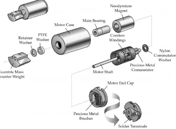
2.2 Exploded cylindrical ERM vibration motor. Coin-shaped ERMs also exist, and are typically more suited for haptic applications since they require no external moving parts. Adapted from [54]. . . 9
2.3 Exploded coin-shaped LRA vibration motor. Adapted from [52]. . . 11
2.4 Abridged representation of a PVA, showing its relaxed and bent states [78]. . 13
2.5 Representation of shape-memory physics. The differences between the cooling and heating transitions are an evidence of hysteresis, meaning that the effect is not without some inherent energy loss [89]. . . 14
2.6 Typical configuration of Passive Haptic Learning (PHL) applied to musical retention [34]. . . 15
2.7 Isolated heart conduction system. Adapted from [18] . . . 16
2.8 Simplified representation of a normal ECG and its typical waveforms. To a trained clinician, these tracings convey a large amount of structural and functional information about the heart and its conduction system. Authored by Hank Diskussion. . . 17
2.9 Pictorial outline of the decomposition of a raw surface EMG recording into its MUAP constituents. Adaptation from [21]. . . 18
2.10 Graphical representation of an ideal SCR. Adapted from [17]. . . 19
2.11 Finger tracking exoskeletons from Dexta Robotics©[69]. . . 22
2.12 Illustrations of typical inertial sensors. Adapted from [25, 86]. . . 23
2.13 Block diagram of a modern 3D game engine. Adapted from [36]. . . 25
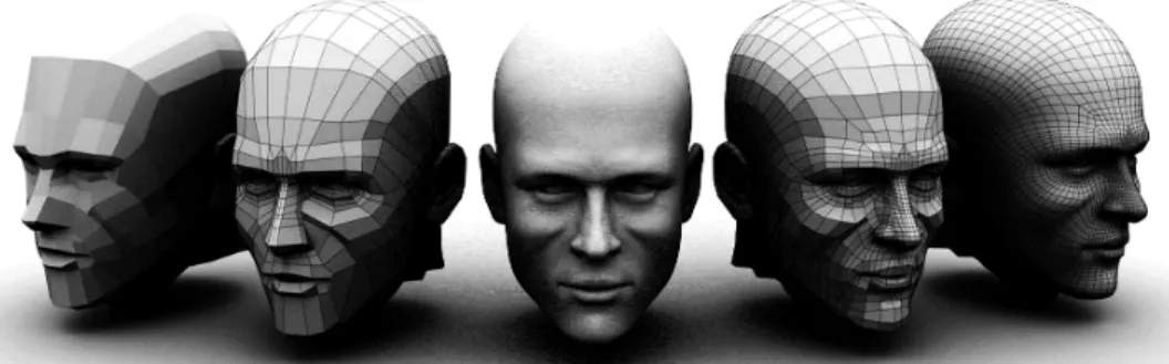
2.14 3D polygonal modeling of a male human head. Poly-count increases from left to right (excluding the middle instance, which illustrates the final outcome). 26 2.15 3D reconstruction of the heart and aorta, based on CT images [7]. . . 27
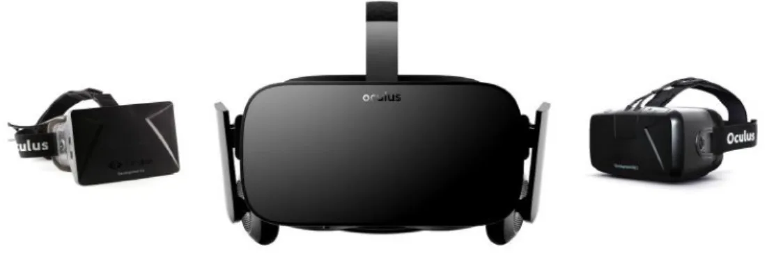
3.1 Evolution of the HMD Oculus Rift©from 2012 to 2016. DK1 on the left, DK2 on the right and the Rift (commercial version) in the middle. Though not depicted, an external IR camera is needed in order for positional tracking to
be enabled (does not apply to the DK1). . . 30
3.2 Sony©’s HMD, Project Morpheus© (in the middle). Much like Oculus’s DK2 and Rift models, it is not a standalone product and requires the PlayStation Eye© (on the left) and PlayStation Move© (on the right) to operate at its full capacity. . . 31
3.3 Developer edition of the HMD HTC©Vive©. . . 32
3.4 Innovator edition of the Gear VR©headset. . . 33
3.5 NeuroDigital©’s tactile feedback device, the Gloveone©. . . 34
3.6 Arduino©’s UNO Rev3 (on the left) and LilyPad (on the right) boards [2, 3]. . 36
3.7 Bitalino©’s hardware modalities: standard credit-sized board on top, plugged version in the middle and freestyle kit in the bottom [60]. . . 37
3.8 Exploded representation of a Leap Motion©controller and its interaction area (results from the intersection of the binocular cameras’ FOVs). Adapted from [56] . . . 38
3.9 Pictorial representation of the Nimble Sense© in its VR mount (on the left) and a schematic of its FOV (on the right). Adaptation form [88] . . . 39
3.10 Myo©expandable armband [83]. . . 39
3.11 Structure of a typical Unity3D© project. As per indicated by self-feeding ar-rows, the game object hierarchy system allows for object parenting. Inspired by [93]. . . 40
3.12 Diagram illustrating Unreal Engine©’s editor as well as its visual scripting functionality (blueprint mechanic). . . 41
3.13 BRAINtrinsic’s UI showcasing the intrinsic geometries of DTI-derived struc-tural and the resting-state fMRI connectomes (middle and right column, re-spectively) as well as their reference in neuroanatomical space (left column). Adapted from [20]. . . 42
3.14 Depiction of the BRAINX3visualizer. The 3D connectome and its overlaying simulations are projected onto the central screen. The one the the right dis-plays regional information referring to the selected areas while the left screen shows 2D axial slices of the brain and highlights regions of activity. Adapted from [4]. . . 43
4.2 Screenshot of the UI of Unity3D©’s editor showcasing just how straightforward the process of creating and adapting content for virtual reality display has become. The checkbox highlighted in cyan in the inspector is the one that controls VR support. . . 47 4.3 Ideal configuration for mounting the Leap Motion onto a HMD [57]. . . 49 4.4 Early sketches showcasing the design intended for the wearable device. The
thick black lines indicate where the wires would pass whereas the flat open surface on the base of the wrist’s topside (on the left) pinpoints the placement site for the haptic module. Male (|) and Female (~) symbols illustrate where their corresponding snap connectors would be sewn. Tactors and their signal-ing LEDs were respectively drawn as big and smaller circles at the fsignal-ingertips and palm of the hand (visible on the palmar view). . . 50 4.5 Different perspectives of the thermal gloves from Artengo©’s tennis collection. 51
4.6 Sketch portraying the pattern design for the glove’s cover. . . 51 4.7 Devised tactor entity. The final prototype (beta) holds 6 of these units (placed
at the tips of the thumb, fingers and palm), while the early one (alpha) has but 5. . . 53 4.8 Schematic showing the circuit configuration used to drive each of the tactor
units (which are also visible). Based on the diagrams suggested in [50]. . . . 54 4.9 Stand-in signals that were fabricated to aid in the calibration of the
imple-mented filters. From top to bottom: EDA (cyan), ECG (green) and EMG (yel-low). For each of these, an event-related threshold that is calculated dynami-cally can be seen (olive). . . 56 4.10 Plots showcasing the outcome of applying the implemented filters as per
spec-ified in table 4.5. In each channel’s tracings, the raw data (at the top) and the end result (at the bottom) are displayed. Additionally, intermediary stages of filtering illustrating the effects of a bandpass filter and a full-length
rectifica-tion can be seen for the ECG and the EMG signals, respectively. All captures pertain to buffers with 20 000 points. . . . 56
4.11 Screenshot of Maya’s UI after optimizing an AAL brain model. The process lowered the mesh’s poly-count from 1.8 M to 0.5 M (72.2 % reduction). . . . 57 4.12 2D representations of an AAL connectivity matrix in its weighted (on the left)
4.13 Sreenshot of TrackVis©’s graphic UI. This particular capture is showing every tract whose length measures more than 20.00 mm and less than 175.28 mm.
N.B., each tract’s voxel is color coded according to how its absolute orienta-tion in a 3D-coordinate system translates into RGB "space" (where right-left corresponds to Red, anterior-posterior to Green and superior-inferior to Blue) - Anisotropic color code. . . 59
5.1 Illustration of our final development framework that emphasizes Unity’s ubiq-uity in the integration of all its software elements. The logo on the far right is a mock-up for our wearable device whereas the leftmost one represents our VR mount. . . 61 5.2 Maya visualizations of the DK1 mount, both in shaded wireframe mode (on
the left) and post-rendering (on the right). Though it it is meant to be used as a single unit, the model was designed as a two-part piece to facilitate the printing process. . . 62 5.3 Photographic composition of the DK1 mount, once printed, assembled (the
picture on the top left corner features the mount’s two constituent pieces) and painted. . . 62 5.4 Maya visualizations of the DK2’s first mount. The fork-like component is
meant to be glued to the one with the Leap-shaped hole, whereas the remain-ing flat one is a cover that snaps onto the rest and secures the controller. . . . 63 5.5 Photographic composition of the first version of the DK2 mount portraying
the various stages it underwent prior to being ready. . . 63 5.6 Maya visualizations of the DK2’s second and final mount, showing its
polyg-onal mesh (on the left) and the result of rendering said mesh (on the right). The trident-shaped sub-piece is to be glued to its Leap-holding counterpart. The latter features two laminae that further add to the overall stability of the model, once it is mounted. . . 64 5.7 Photographic composition of the final version of the DK2 mount illustrating
the various production stages that led to its final outlook. . . 64 5.8 Assortment of photographs that depict some of the tests that were performed
with the early versions of the glove’s haptic module. Using Unity’s physics engine, we were able to detect collisions between the user’s hand and a hapti-cally responsive object (the sphere that is barely visible in the laptop’s screen) with finger specificity. . . 65 5.9 Collection of photographs that show the alpha prototype of our haptic device.
These images display our right thermal glove (reffered in section 4.5.1) worn
5.10 Brief portfolio of photographs that showcase the final electrophysiology mod-ule. The two smaller images on the left focus the plug-in entry points for the ECG, EMG (both on the top left corner) and EDA (bottom left) sensor-blocks while the pair on the right, emphasizes the micro USB port on the power block (top right corner) and the battery’s hookup site (bottom right corner). . . 67 5.11 Photographic composition that exhibits our final haptic module (minus the
tactor units). The two images on the extremities display the custom-made shield with the driving circuitry soldered onto it, whereas the one on the middle portrays it plugged into the Arduino©UNO Rev3 board. . . 67 5.12 Series of photographs that summarize the device’s integration process. The
larger picture on the right portrays its final product, whilst those on the left display the tactor-concealing cover (two at the top) as well as the thermal glove by itself, with the EDA hole cut into it and the tactor units already in place (two at the bottom). . . 68 5.13 Assemblage of photographs that illustrate the constructed wearable device in
use. The two images on the far ends captured the glove while all its tactor units were simultaneously active, whereas the one in the middle shows the proper configuration of the device’s EMG and EDA electrodes. . . 68 5.14 Screenshot of Unity’s editor while running BCL. The variables highlighted
in cyan inside the "Connectome" inspector are the ones we presented in this section. . . 71 5.15 Class diagram that schematizes the connectomic portion of BCL’s structure.
Plus (+) and minus (-) signs refer to public and private members, respectively. Links with solid arrowheads represent the storage of instances of the originat-ing class in the receiver’s, while plain ones denote instantiations (e.g."Graph" instances are created in the "Connectivity" script, and assigned to member variables in the two "Segment" instances they connect as well as in the "Con-nectomeManager"). . . 72 5.16 Instances of the MRI reconstructed brain meshes in Unity. From left to right:
AAL, HOA (cortical), HOA (subcortical), DKCA and DCA parcellated models. 73 5.17 Screen captures of AAL connectivity networks with different color codes
ap-plied onto them. The leftmost one is colored according to the Anisotropic code whereas the one adjacent to it showcases a healthy matrix encoded with Referential colors. As do the two images on the right, though these stemmed from two distinct epileptic matrices. . . 73 5.18 Screenshots of an AAL connectome, after is has been expanded/exploded. . 74 5.19 Comparison between the tractography visualization tool we created in Unity
5.20 Portrayals of each of the One Handed Interaction tools. From left to right: Point & Select, Translate, Rotate and Hover & Select/Deselect. Notice how the pattern on the back of the hand changes to indicate how many extended fingers the Leap is seeing. . . 75 5.21 Representation of BCL’s use of the VR Widgets. From left to right:
Introduc-tion scroller, Adjustment sliders and SelecIntroduc-tions scrollers. Also from left to right, each slider’s function is to: adjust the brain’s opacity, adjust the net-work’s luminosity, control the type of color code being applied (Referential or Anisotropic) and lastly, its amount. . . 76 5.22 Depiction of our recognizable gestures. The images on the extremities
illus-trate the left and right Trigger gestures, while the one in the center shows a double Pinch. Notice that visual cues specific to each gesture and hand appear on the respective corner of the screen when a gesture is properly performed. 76 5.23 Gender-specific hand models included in BCL. The male ones can be seen on
the images to the left while their female cohorts are displayed on the right. Notice how each hand has its own signature color and how it is the negative of its counterpart’s. . . 77 5.24 Ode to Joy’s musical sheet. Arrangement by Lester Bailey. . . 77 5.25 Graphical UI of Ode to PHL. The white circle in the middle of the screen
moves according to the note that is being played. The standard slider adjusts the tempo and the "Restart" button resets the sequence (which is continuously looping otherwise). . . 78 5.26 Maya visualizations of the scalpel model that was created for the Surgery
Simulator, both in shaded wireframe mode and rendered mode. . . 79 5.27 Screenshots of an execution of our Surgery Simulator application. The picture
2.1 Implemented brain parcellation atlases [14, 22, 23, 85]. . . 28
3.1 Technical comparison between Oculus’s HMD versions. Since the Rift has not been released yet, some of its specs remain unknown at this time (marked with a "-") [13]. . . 30 3.2 Technical specs of the Project Morpheus©HMD. Again, uncharted parameters
are marked with a "-" [79]. . . 31 3.3 Technical aspects of the HTC Vive©HMD. Once more, undisclosed
specifica-tions are indicated with a "-" [35]. . . 32 3.4 Technical specifications for Samsung©’s Innovator edition HMD, Gear VR©.
As before, unknown specifications are marked with a "-" [73]. . . 33 3.5 Technical specs of the UNO Rev3 and LilyPad prototyping boards [2, 3]. . . . 36
4.1 Utilized versions of Unity3D©in chronological order. . . 45 4.2 Specifications of the components used to make the final tactor units. . . 53 4.3 Specifications of the parts that where used in the making of the driving circuit. 54 4.4 Specifications of the parts that where used in the assembly of the glove’s
elec-trophysiology module. It is important to note that the prices listed are unitary and that the actual freestyle kit (which includes some additional parts) is quoted at 159€. . . . 55
4.5 Channel-specific filter configuration that was used in any and all interfaces that featured our electrophysiology module. N.B., these are mere recommen-dations reflecting what resulted best for our applications and as such, ought to be adjusted if required. . . 56
.DICOM Digital Imaging and COmmunication in Medicine.
.FBX Filmbox.
.NIFTI Neuroimaging Informatics Technology Initiative.
.OBJ wavefront Object.
.STL Stereolithography.
.trk Track.
.txt Text.
2D Two-Dimensional.
3D Three-Dimensional.
AC Alternating Current.
AI Artificial Intelligence.
API Application Programming Interface.
AR Augmented Reality.
AV Atrioventricular.
BCL Brain Connectivity Leap.
BIH Brain Informatics & Health.
BVP Blood Volume Pulse.
CT Computed Tomography.
DC Direct Current.
DK Development Kit.
DTI Diffusion Tensor Imaging.
ECG Electrocardiogram.
EDA Electrodermal Activity.
EEG Electroencephalography.
EMG Electromyogram.
ERM Eccentric Rotating Mass.
fMRI functional Magnetic Resonance Imaging.
FOV Field Of View.
FPS Frames Per Second.
HCI Human-Computer Interaction.
HMB Haptic Mitt Bit.
HMD Head Mounted Display.
I/O Input/Output.
IBEB Instituto de Biofísica e Engenharia Biomédica.
IDE Integrated Development Environment.
IICISGP II Congresso Internacional da Saúde Gaia-Porto.
iLIDH Luso-Illyrian Institute for Human Development.
IMUs Inertial Measurement Units.
IR Infrared.
LED Light Emitting Diode.
LRA Linear Resonance Actuator.
LxMLS Lisbon Machine Learning School.
MEMSs Micro Electro-Mechanical Systems.
MIBCA Multimodal Imaging Brain Connectivity Analysis.
MRI Magnetic Resonance Imaging.
MU Motor Unit.
MUV Museum of Universal Values.
PCB Printed Circuit Board.
PET Positron Emission Tomography.
PHL Passive Haptic Learning.
PVA Piezoelectric Vibration Actuator.
PWM Pulse Width Modulation.
RAM Random-Access Memory.
RF Radio Frequency.
RGB Red-Green-Blue.
ROIs Regions Of Interest.
RPM Revolutions Per Minute.
SA Sinoatrial.
SCL Skin Conductance Level.
SCRs Skin Conductance Responses.
SDK Software Development Kit.
SI Système Internationaleor International System.
SMA Shape Memory Alloy.
SNR Signal-to-Noise Ratio.
TOF Time of Flight.
UI User Interface.
USB Universal Serial Bus.
C
h
a
p
t
1
I n t r o d u c t i o n
1.1 Context & Motivation
With the exponential growth in technology, connectivity and automation of the late XX and beginning of XXI centuries, a want for interfacing the digital and real worlds emerged and soon matured into a need, leading to the development of Virtual Reality (VR) and Augmented Reality (AR) interfaces - technologies that provide a link between the user and a computer-generated synthetic environment. The more fluid and seamless the transition between the two domains, the less detached the user feels about the interaction and the more intuitive it becomes [57].
With that in mind, one should only stand to gain from an approach with multisensory integration when designing such an interface [95]. Endowing a VR/AR application with a stereoscopic Head Mounted Display (HMD), a stereophonic sound system and the ability to atleast partially exploit the human haptic sense, would only enhance its functionality and benefit the end-user’s state of immersion. The latter sense deserves special considera-tion given that unlike the visual and auditory systems, their haptic counterpart is capable of both perceiving and acting on the environment [95]. A realization that in and of itself opens up a wide array of possibilities for software and hardware developers alike.
Adding a layer of physiological computing to said interface, enables the subject’s Electrocardiogram (ECG), Electromyogram (EMG) and Electrodermal Activity (EDA) to be acquired in a non-invasive fashion and processed at run time. These biosignals and the features they entail, can subsequently be used to dynamically affect and modulate
the constructed landscape, effectively laying down the foundations for biofeedback to be
Couple these features with a reliable hand motion tracking mechanism, and not only is the interactivity of the system taken to new heights but the aforementioned immersion is accentuated even further. This would allow users to rely on their proprioception to control their movements and better understand depth, ideally up to a point where the "mind’s eye" is fooled and true enthrallment is achieved [57].
In few other health related disciplines is attaining such levels of realism and captiva-tion more crucial than it is so in rehabilitacaptiva-tion. However, the branch does not stand alone in such regard. Accurately designing task-driven, engaging and motivational experiences can be determining not only when dealing with the innate lethargy that often ails ther-apy patients but also in educational, diagnostic and surgery settings [42, 90]. Moreover, having access to both real-time and offline electrophysiological data provides overseers
with valuable insights to aid in their clinical and/or evaluation assessments [26].
Thus, the present dissertation was prompted. It proposes an innovative approach towards the development of wholesome VR/AR applications by integrating existing state of the art media and complementing them with a novel wearable device. A glove capable of not only conveying tactile feedback to its wearer but also acquiring electrophysiological data at run time, hence bringing physiology into the VR/AR scene.
1.2 Objectives
The core focuses of this thesis are then to, first and foremost, create the necessary tools for the development of cohesive multimodal VR/AR interfaces with educational and clinical applicability. And last but not least, to employ and showcase them in the conception of a set of applications that fall into the aforesaid categories. In order to reach these marks, the following milestones were set:
• Design and materialization of a physical VR mount with which to attach the hand tracking controller from Leap Motion©onto the HMD from Oculus Rift©;
• Design and confection of the glove’s textile elements;
• Design and assembly of the haptic feedback module using a microcontroller-based prototyping platform from Arduino©;
• Design and soldering of the device’s electrophysiology component resorting to the Bitalino©Freestyle Kit;
• Building the glove’s Software Development Kit (SDK), in which a haptic stimuli library, a signal processing toolkit and gesture recognition algorithms are included;
• Integration of the final wearable device with the HMD from Oculus Rift©and the Leap Motion©controller in Unity3D©(chosen development platform);
1.3 Dissertation Overview
The present chapter consists of a brief preface to the proposed thesis and as such, focuses mainly on its scope, motivations and goals. From this point onward, its structure is organized as follows:
• Chapter 2sheds some light on pertinent, and otherwise unfamiliar to most, theoreti-cal notions that were deemed fundamental to the understanding of this dissertation. These will be addressed in a thorough albeit comprehensive manner;
• Chapter 3 accounts for an exhaustive review of the literature pertaining to the current state of the art in the fields related to this project. To accomplish this, concrete examples of technologies, methodologies and designs of relevance are presented according to the category in which they insert themselves.
• Chapter 4performs a step-by-step chronological scrutiny of the resources and meth-ods that were deployed in order to meet the requirements set by the appointed objectives;
• Chapter 5summarizes this dissertation’s key results by disclosing our final frame-work, its principal constituents along with the applications that derived from them;
C
h
a
p
t
2
T h e o r e t i c a l C o n c e p t s
2.1 Virtual Reality
The termVirtual Realityis credited to Jaron Lanier, who first coined it in the 1980’s to differentiate between traditional computer simulations and those that involved multiple
users in a shared environment. Since then, and given the span of its embrace, its meaning has been continuously tweaked by generations of academics, software developers and researchers who delved into the realm.
In accordance with today’s definition, it can be thought of as a visceral form of digital display, through which one can be transported into an evermore Three-Dimensional (3D) synthetic form of real or imagined worlds [68].
As expected, development in VR frequently goes hand in hand with concepts such as immersion, interactivity and involvement, and more often than not, these end up serving as benchmarks to label the resulting interfaces. Depending on the pondered criteria, VR experiences can then be classified as either passive, exploratory or interactive (or any combination of these) [12, 24].
Given its stature as an emerging medium, VR still stands as a fairly esoteric and specialized discipline. Because of this, certain aspects pertaining the best practices for content creation in the field are yet unstudied to a point where authoritative statements cannot be made. That being said, observational theories do exist as to prevent the devel-opment of poorly conceived interfaces, which once combined with sub-optimal hardware generally increase the odds of triggering Simulation Sickness1[57, 68]. To circumvent this issue, extensive user testing remains an absolute necessity and a crucial step towards designing comfortablein silicoexperiences.
1Combination of symptoms clustered around eyestrain, disorientation, and nausea that arise from
2.2 Augmented Reality
The underlying notion ofAugmented Realitycan be considered as a subcategory of a more encompassing albeit less disseminated concept called Mediated Reality, in which the user’s perception of the physical world is not necessarily augmented, but can conversely be diminished.
AR contrasts with VR mainly in the composition of their simulation spaces. Whereas the latter are entirely computer-fabricated, the former raise the system’s complexity by superimposing a layer of virtual elements on a view of the real world2, ergo, augmenting it. Even the slightest misalignment in the integration process is enough to compromise immersion and incite disengagement, which is why it comes as no surprise that object recognition and other image processing algorithms play a big role in AR [12, 39].
Up until the insurgence of smartphones and tablets, AR was mostly restricted to large-scale scientific or military projects. However, recent developments in mobile technologies have significantly widen its audience and boosted independent research. Thereafter, AR data visualization applications related to navigation, advertising, art, education, tourism, entertainment, medicine (an example can be seen in figure 2.1) and so on are beginning to see the light of day [29].
Figure 2.1: VeinViewer©is an AR medical application that uses IR reflection to compute patterns of superficial veins. These are then projected them onto the patient’s skin.
2.3 Haptics
When debatingHaptics, some ambiguity is bound to arise. One may be referring to the human haptic system or to the technologies that hope to either probe, emulate or interact with it. By elaborating on both of these topics, we hope to clear the veil of confusion that often clouds the definition of haptics.
2.3.1 Haptic Sense
More commonly dubbed as our sense of touch, or tact, theHaptic Senseis a key player in the overall spectrum of human exploratory procedures [37, 92]. As section 2.3.3 will shortly adress, it is closely related to muscle memory and therefore cannot be dissociated from the process by which motor skills are apprehended [75]. Roughly speaking, it can be broken down into two submodalities that differ mainly on the type of sensory information
that is dealt with by them [10, 95].
• Tactile(or cutaneous) information is usually associated with texture, temperature and vibration. That first sense of contact whenever we touch an object’s surface, happens when this kind of information is captured by specialized thermal and mechanical skin receptors which then send it through afferent neural pathways to
be processed by the parietal lobe in the cerebral cortex [11, 84];
• Kinesthetic(or proprioceptive) information on the other hand, has to do with the pressures, forces and motions that we perceive when interacting with the physical world. It is how we can discern the weight of an object just by holding it. Some of the object’s features are not sensed directly though, but rather extrapolated from the relative positions and movements of the intervenient body parts [10, 95];
Notwithstanding their simultaneity and the fact that their separation is far from phys-iologically established, for the purpose of this dissertation, whenever the term "haptic sense" is invoked from this point onward, it shall be referencing its tactile component (unless explicitly saying otherwise) [10].
2.3.2 Haptic Technology
From a technological point of view, haptics tries to entice the supra referred senses of touch and kinesthesia to convey pertinent information - Haptic Feedback.
In fact,Haptic Technologynow stands as a candidate in tackling one of the defining problems of our age: Information Overload, a direct consequence of an unprecedented unrelenting contact with the digital world through electronic devices that bombard us with visual and, to a lesser extent, auditory stimuli. In the words of Professor Karon MacLean, "People are not biologically equipped to handle the assault of information that all comes through one channel" [47].
Nevertheless, high production costs associated with a lack of a standard Application Programming Interface (API) and established User Interface (UI) conventions have some-what limited a widespread market acceptance for haptic appliances [92]. This does not necessarily constitute a deterrent to venturing on the field but can on the contrary, be construed as an opportunity.
Historically speaking, the pioneer haptic devices that fell into the tactile category, were inspired by matrix pin-printers resembling those used in braille systems for the blind [10]. Today however, they have evolved into relying mostly on localized vibration actuators, known as Tactors [92]. These vary with respect to their response times, capacity to generate different waveform patterns, power requirements and functioning principle
[5]. As such, vibrotactile actuators can be divided into different tiers. In light of their
importance to this project and presence in applications of biomedical importance, the following four shall be given special emphasis:
• Eccentric Rotating Mass (ERM);
• Linear Resonance Actuator (LRA);
• Piezoelectric Vibration Actuator (PVA);
• Shape Memory Alloy (SMA);
2.3.2.1 Eccentric Rotating Mass Motors
An ERM vibration actuator is, in its essence, an electromagnetic Direct Current (DC) motor with an off-centered mass attached to a shaft (represented in figure 2.2). As said
asymmetrical mass rotates, it generates a non-null net centripetal force that ensues in the motor’s displacement.
The shaft’s rotation is achieved by applying a current to its armature windings. As these are inside a permanent magnetic field, Lorentz law dictates that a torque be applied on the shaft. To ensure the direction of rotation is maintained, the current in the windings has to be regularly reversed. This can be accomplished through the use of static metal brushes at the ERM’s terminals that intermittently contact the different segments of a
rotating commutator [52].
With a sufficiently high count of Revolutions Per Minute (RPM), the motor is
con-stantly being moved in the plane perpendicular to the shaft’s axis. The resulting rapid and repeated displacement is what is perceived as vibration [54].
Figure 2.2: Exploded cylindrical ERM vibration motor. Coin-shaped ERMs also exist, and are typically more suited for haptic applications since they require no external moving parts. Adapted from [54].
This effect is generally unwanted in engineering pursuits, since it is often associated
To evaluate ERM performance, two metrics of vibration are commonly quoted:
• Vibration Frequencyis the frequency at which the tactor oscillates and is fairly sim-ple to derive since it depends exclusively on the motor’s rotation speed (formalized in expression 2.1);
ν=νRPM
60 (2.1)
ν→vibration frequency [Hz];
νRPM→motor speed [RPM];
• Vibration Amplitudeon the other hand, has a bit more complexity to it. As shown in equation 2.2, the centripetal force generated by the motor depends on the mass of the off-centered load, on the motor’s eccentricity3 and on its angular velocity.
However, this does not tell the whole story. The total vibration amplitude also depends on the mass of the object to which the ERM is attached. If the total mass of the system is known, its acceleration can be calculated by applying Newton’s second law of motion (also represented in equation 2.2). From there, it is a simple matter of multiplying it by the the earth’s gravitational acceleration to obtain the vibration amplitude of the system in its standard unit (notSystème Internationaleor International System (SI)). In order to facilitate comparison among different ERM
models, a typical normalized amplitude of vibration is cataloged. This pragmatic measurement expresses the level of vibration that the ERM in question produces when driven at its rated DC voltage in a system weighting 0.1 kg [54];
Fctp=merω2=Ma= (me+mo)a≡Ag=
Fctp
(me+mo)G
(2.2)
Fctp→centripetal force [N];
me→eccentric load’s mass [Kg];
r→eccentricity radius [m];
ω→angular velocity [rad.s−1];
M →total mass of the system [Kg];
mo→attached object’s mass [Kg];
a→acceleration of the system [m.s−2];
Ag→vibration amplitude [G];
G→earth’s gravitational acceleration [m.s−2];
To sum up, we have established that varying the input DC voltage of a system powered by an ERM, changes the centripetal force produced by it which by extension affects the
system’s frequency as well as its amplitude of oscillation. Thus deeming impossible their independent manipulation.
2.3.2.2 Linear Resonance Actuators
While still in the gamma of electromagnetic tactors and despite operating on a similar basis (where a moving mass creates an unbalanced force that repeatedly displaces the mechanical system), LRAs differ greatly from their ERM counterparts. Unlike the latter,
linear resonance motors use an internal magnetic mass attached to a spring to create mo-tion. An Alternating Current (AC) through the LRA’s coils (visible in figure 2.3) generates a fluctuating magnetic field that drives the inner mass back and forth in its direction, resulting in a force that causes displacement [52, 53].
The described system depicts a basic example of a driven harmonic oscillator, in the sense that when disturbed by an external force, it experiences a restoring one (exacted by the spring) that moves it towards its equilibrium position. This means that the device vibrates with greater amplitude when driven at particular frequencies - Resonance. Con-sidering that the electromagnetic force that is felt by the mass’s permanent magnet only acts in a single axis (perpendicular to the wider surface of the LRA’s casing), it follows that its movement is also restricted to it. This "Linear Resonant" behavior is where the actuator gets its name [53, 54].
Figure 2.3: Exploded coin-shaped LRA vibration motor. Adapted from [52].
Being that they focus on efficiency, these vibrotactile actuators are usually associated
On the other hand, they do offer a couple of pivotal benefits that might render them
the better option for finished products, specially when it comes to implementing haptic feedback. To name a few of these, we can highlight the fact that when compared to ERMs, LRAs have lower response times, meaning they can start to vibrate more quickly and stop equally as fast. This leads to a more realistic haptic response. Furthermore, having no electromechanical commutation and being effectively brushless4translates into less
mechanical wear and thereby, much longer lifespans. Even the driving requirements that might make them less appealing at early stages of development, grant them an additional edge for final applications. This holds true because most LRA driver chips offer a wide range of specialized utility features that optimize overall performance (such
as automatically detecting resonant frequencies and providing waveform libraries) [53, 82]. Lastly, relying on resonance to operate implies that there is no direct correlation between the input’s amplitude and its nearly invariant frequency. This allows for the use of more complex excitation waveforms which in turn, result in a richer haptic experience for the user [51].
2.3.2.3 Piezoelectric Vibration Actuators
These non-magnetic vibrotactile displays function on the premise that when strained, piezoelectric materials store charge. Conversely, when a DC voltage is applied to them, their shape is altered. If an AC input is used instead, multiple and successive deforma-tions occur,i.e., vibration [77] (this effect is portrayed in figure 2.4).
Figure 2.4: Abridged representation of a PVA, showing its relaxed and bent states [78].
This seamless conversion between mechanical and electrical energies award PVAs with a certain duality in regard to their purpose. Provided that the system’s architecture adapts to their circumstantial role, they can be used not only as actuators but also as sensors. Adding to this feature, there are several others to be pointed out, that presumably give these tactors a competitive advantage over their electromagnetic cousins:
• Static Deflection refers to the capability to maintain a static DC driven curva-ture. Besides allowing for the illusion of height in certain UI elements of Two-Dimensional (2D) displays, this can be used to constrain certain movements in wearable applications - Kinesthetic Feedback;
• Independent Frequency, Amplitude and Phasemanipulation adds a layer of cus-tomization to the feedback that is produced. As we have discussed in sections 2.3.2.1 and 2.3.2.2, such level of control simply cannot be attained with ERMs, and only partially can it be so with LRAs;
• High Frequency accredits these actuators with the ability to comply with high paced excitation impulses such as square waves and step functions;
• No Magnetic Signaturemeans that piezo actuators can be used near magnetism-sensitive devices,e.g.compasses, Random-Access Memory (RAM), Radio Frequency (RF) antennas and even Magnetic Resonance Imaging (MRI) machines;
• Low Currentneeds make PVAs an asset in wearable electronics, where low gage,
i.e.thin, fabric-embedded and high-flex wiring is required;
2.3.2.4 Shape Memory Alloys
Smart metals and muscle wires are just a couple of the colloquial aliases given to SMAs. The reason being that when heated above a characteristic threshold, these composites are able revert any existing deformation and return to their predefined original shapes, as if they "remembered" them. This phenomenon can be observed even with unusually large amounts of strain - Superelasticity.
In other words, SMAs can exist in two different phases, Austenite and Martensite.
Transition between the two is diffusionless,i.e.time-independent, and dictated solely by
the material’s temperature and stress. While at its martensitic state, a SMA can be molded into any arbitrary shape. Said deformation is then maintained until the alloy is heated up beyond itsAstemperature (refer to figure 2.5 for this and any other subsequent variable allusions regardind the shape-memory effect), at which point it starts to regress into its
austenitic shape. Once the temperature reaches the value ofAf, the transformation is complete [89, 91]. Analogously, we could enforce the same rationale to explain how the cooling process unfolds.
Figure 2.5: Representation of shape-memory physics. The differences between the
cool-ing and heatcool-ing transitions are an evidence of hysteresis, meancool-ing that the effect is not
without some inherent energy loss [89].
As→start temperature for martensite to austenite transitions;
Af →temperature of completion for martensite to austenite transitions;
Ms→start temperature for austenite to martensite transitions;
Mf →temperature of completion for austenite to martensite transitions;
Since these reversible shifts can be driven by the resistive heating that an electric current flowing through a shape-memory wire creates, adopting this technology to haptic actuation becomes a matter of choosing the appropriate thermo-mechanical configuration [94]. However excellent the power-to-weight ratio and intrinsically high stiffness of SMAs,
2.3.3 Passive Haptic Learning
Krugman and Hartley eloquently define passive learning as "typically effortless,
respon-sive to animated stimuli, amenable to artificial aid to relaxation and characterized by absence of resistance to what is learned" [41]. Passive Haptic Learning (PHL) embod-ies these traits to facilitate the apprehension of motor skills through haptic stimulation while little to no attention is dedicated to the process [75]. In fact, this mechanism has proven its effectiveness even when the subject is actively engaged in distraction tasks (e.g.
completing a standardized test, watching a movie, walking a path) [40].
Most literature on the topic refers to its application in the process of learning and rehearsing relatively simple one-handed piano passages (i.e.sequences of 10-15 notes), through usage of haptic gloves with embedded vibration motors (in a configuration that resembles the one illustrated in figure 2.6) [40, 48]. However, recent studies have also proven its adequacy when it comes to acquiring and honing more challenging skills such as typing and reading Braille or playing two-handed chorded piano melodies [74, 75].
Figure 2.6: Typical configuration of PHL applied to musical retention [34].
Considering the limited amount of free time the typical adult has at his/her disposal, devoting a portion of it to actively learn high maintenance competences like playing an instrument can be a cumbersome and frustrating struggle. Specially considering that learning to play any given song once is insufficient. As soon as it is learned, forgetting
2.4 Electrophysiology
Electrical signaling is one among the fast communication channels of cells and tissues within living organisms.Electrophysiologyis the branch of physiology that concerns itself with the acquisition, processing and analysis of these ionic currents [31, 64].
Its resolution envelops measurements on a wide variety of scales, ranging from single ion channel proteins to whole organs. Given this thesis’s context, we will focus more towards the latter.
2.4.1 Electrocardiography
Heartbeats are triggered by low amplitude electrical impulses, generated by a special-ized aggregate of fibers - the Sinoatrial (SA) node5[61]. These cardiomyocytes have the characteristic ability to spontaneously and periodically depolarize. Considering that in cardiac tissue, neighboring myocites are electrically coupled via low-resistance channels,
i.e.gap junctions, and that these allow for direct ion exchanges between adjacent pairs, it follows that a single action potential can initiate a cascade of intercellular currents [31]. When that is the case, the exciting potential propagates throughout the cardiac conduction system (depicted in figure 2.7) and ultimately leads to a contraction, a beat.
Although they do not stand alone in such regard, meaning that there are other fibers in the heart capable of prompting contractions, the SA cells are normally the ones to set the pace, simply because they have a higher frequency of depolarization. For this reason, the SA node is commonly termed as the heart’s natural pacemaker.
Figure 2.7: Isolated heart conduction system. Adapted from [18]
Electrocardiography(ECG) is the process by which the aforestated electrical activity is
detected, translated into numerical values and then recorded over a period of time [61]. To do this, electrodes are placed in contact with the subject’s skin, where the myocardium’s depolarization potential yet reverberates with a measurable intensity.
The resulting electrocardiogram tracings (exemplified in figure 2.8), greatly depend on the used electrode configuration. In a conventional 12 lead ECG, 4 are distributed over the patient’s limbs and 6 are placed on his/her chest surface. What is then measured, is the heart’s overall electrical potential from 12 different angles, ergo "12 lead ECG".
Although this approach produces valuable information that can help diagnosing and monitoring underlying medical conditions, simpler ones exist for applications with less demanding purposes. Examples of these are a configuration in which 1 electrode is placed at each hand and another where 3 electrodes are placed at the chest [61].
Figure 2.8: Simplified representation of a normal ECG and its typical waveforms. To a trained clinician, these tracings convey a large amount of structural and functional information about the heart and its conduction system. Authored by Hank Diskussion.
P wave→Indicates atrial depolarization, which leads to the contraction of the atria. For reasons listed above, the right atrium depolarizes slightly earlier than the right one;
PR interval→Period between the onsets of atrial and ventricular depolarizations. Correlates to the transmission delay imposed by the Atrioventricular (AV) node;
PR segment→Flat isoelectric section that reflects the depolarized state of the atria;
QRS complex→Announces ventricular depolarization, which coincides with and therefore obscures atrial repolarization. Given its amplitude, it is usually the marker
used for peak detection and heart rate calculations;
QT interval→Period between the depolarization and repolarization of the ventricles;
ST segment→Flat isoelectric section that reflects the depolarized state of the ventricular chambers;
T wave→Marks the repolarization of the ventricles;
U wave→Not always seen due to its low amplitude, this waveform is thought to represent the repolarization of the Purkinje fibers;
It is important to note that intervals differ from segments, in the sense that the former
2.4.2 Electromyography
Electromyography(EMG) is a technique that focuses on acquiring and evaluating the
elec-trical activity that precedes muscular contraction in skeletal muscles. This electromyo-graphic signal (instantiated in figure 2.9) is essentially a collective of superimposed action potentials from bands of neurologically or artificially stimulated muscle fibers - Motor Unit Action Potentials (MUAPs) [19, 21]. These waveforms provide relevant insights about the anatomy and physiology of the Motor Unit (MU), and thereupon about the muscle these insert themselves in.
Figure 2.9: Pictorial outline of the decomposition of a raw surface EMG recording into its MUAP constituents. Adaptation from [21].
Concerning instrumentation, methodology and produced results, two detection ap-proaches can be distinguished:
• Surface EMG assesses muscle function in a non intrusive manner by measuring the potential difference between one or more pairs of surface sensors placed on
the skin above the muscle (as seen in figure 2.9). This bipolar configuration is ideal for high Signal-to-Noise Ratio (SNR) in the acquired data [63]. However, the method is not without its drawbacks. Reliably discriminating between discharges of adjoining muscles is unfeasible. Moreover, these recordings are restricted to superficial muscles and as such, are influenced by the depth of the subcutaneous tissue in the vicinity of the detection sites, which in turn is highly variable both inter- as well as intra-patients;
• Intramuscular EMG is performed either with needle or fine wire sensors placed within the muscle/s of interest [21]. Although it requires skin penetration and can only monitor smaller areas of said muscle, this method attenuates the significance of some of the limitations that affect surface EMG [59];
2.4.3 Electrodermal Activity
Autonomic changes in the electrical properties of the skin are comprised by the notion
ofElectrodermal Activity(EDA). Said variations are modulated by the secretion levels of
eccrine sweat glands, found virtually in all skin albeit with a considerable higher density in the palmar and plantar regions (hands and feet, respectively). Their high susceptibility to psychologically significant stimuli gives EDA its stature as an invaluable index of change in sympathetic alertness and arousal, which in turn is tractable to emotional and cognitive states [17, 62].
The most widely studied property of the EDA complex is skin conductance, which can be quantified by applying a potential difference between two points in the skin surface
and measuring the current that flows between them. The resulting measurements include a background tonic component - Skin Conductance Level (SCL) - as well as rapid phasic events - Skin Conductance Responses (SCRs). An instance of the latter and its typically analyzed features can be seen in figure 2.10 [17].
Figure 2.10: Graphical representation of an ideal SCR. Adapted from [17].
Fluctuations in psychological homeostasis in response to internal or external stimuli are loosely described in terms of "stress" [16]. From an evolutionary point of view, short term stress reactions are beneficial to the organism in the sense that they help it adapt to the stressor, i.e., the stimulus that elicited the response. However, long term expo-sure to stressful situations and environments may lead to adverse effects,e.g.decreased
productivity, distress, illness and mental breakdown [76].
2.5 Biofeedback
Biofeedbackis an emerging yet increasingly credited technology in the field of
alterna-tive medicine. It can be summed up as a method for conscious manipulation of one self’s physiological activity with the finality of improving health, well being and overall performance [1, 6].
Although it is not mandatory, the process can be reinforced through visualization of some of physiology’s signature markers,e.g., heart function, brainwaves, breathing and skin properties (both thermal and electrical). These traits can be quantified by biomedical equipment and then shown, or "fed back", to the user. Through practice and study, the subject can learn how to purposefully alter these signals and in the process, effectively
affect his/her health. Over time, this skill can be mastered, eventually up to a point
wherein continued use of auxiliary instruments is no longer necessary.
This deployable but affordable technique has proven its legitimacy as a
complemen-tary clinical and therapeutic tool in the treatment of over 100 illnesses, producing par-ticularly positive outcomes in those where motivation and progress awareness are key agents of recuperation [1, 6].
As we have hinted in the previous section (2.4), any approach to biofeedback that could potentially stem from the framework assembled in this thesis would have to be centered mostly around the user’s ECG, EMG and EDA signals6. In spite of not having developed any applications that exploit these phenomena ourselves, we reckoned it still merited a mention in the present chapter.
2.6 Motion Tracking
The systematical study of animal locomotion,i.e., gait analysis, has been an active research topic in biomechanics ever since the 1980’s [6]. Interest has not dwindled in recent years, particularly in the case of humanMotion Tracking, a submodality within the field that is given special focus in light of its potential in clinical and commercial applications [96].
Researchers are continuously trying to develop dynamic systems that can provide real-time data that is representative of changes in body poses while minimizing monetary costs and procedural intrusiveness. When evaluating the overall performance of these motion capture systems, several other aspects must be taken into consideration [70]:
• Temporal Resolution is dictated by the system’s sampling rate, which translates the frequency at which information is read;
• Spatial Resolutionindicates the smallest motion that the sensors can register;
• Latencyis the delay between the actual motion and its detection by the sensors;
• Accuracyaccounts for the amount of error in the performed measurements;
• Robustnessreflects adaptability to different environmental settings;
• Rangedelimits the optimal tracking distance between the sensors and the target;
• Degrees of Freedom (DOFs) relate to the number of independent variables that the tracker uses to quantify motion;
• Reference can either be absolute, in the sense that motion is measured against a fixed coordinate system, or relative to previous measurements. It is important to note that the latter frame can lead to cumulative errors - Drift;
• Mobilityrates the system in terms of portability. Logically, this cannot be dissoci-ated from its weight, size and wired/wireless nature;
The parameters listed above can be heavily conditioned by the functioning principle of the sensing technology in focus. Because of this, the impending sections will address each of the presently listed types of existing systems individually:
• Acoustic Systems;
• Mechanical Systems;
• Magnetic Systems;
• Inertial Systems;
2.6.1 Acoustic Systems
Typically,Acoustic Systemsrely on several sound emitters and atleast three receivers to triangulate position. The emitting markers (e.g. microphones) are placed at strategic locations of the body that is being tracked, while the receptors (e.g. loudspeakers) are arranged in an orthogonal configuration at the capture site. Since the traveling speed of sound is known, tri-axial distances can then be extrapolated from the measured time intervals between emissions and receptions - Time of Flight (TOF) method (formalized in equation 2.3). To differentiate tracers from one another, they are can either be activated
in a sequential manner or they can each have their own signature frequency [58].
Although it should not come as a surprise that the roles of emitters and receivers are interchangeable, the described setup is usually favored. Additionally, a fourth receiver can be fixed in order to dynamically measure the speed of sound and therefore minimize errors due to changes in humidity and temperature.
Dij=∆tijvs= (tj−ti)vs (2.3)
Dij→distance between emitteri and receiverj [m];
∆tij→time of flight between emitteriand receiverj [s];
vs→speed of sound [m.s−1];
ti→instant of emission [s];
tj →instant of reception [s];
The fact that this technology uses lightweight, low-cost and high resolution sensors, is often counter-weighted by issues related with robustness, range, wiring and reflections.
2.6.2 Mechanical Systems
Mechanical methods for capturing body motion require some form of rigidly articulated external structures,i.e., exoskeletons (see figure 2.11). Positions of interest in Cartesian space are inferred from the joint angles of these kinematic chains - Forward Kinematics.
Figure 2.11: Finger tracking exoskeletons from Dexta Robotics©[69].
2.6.3 Magnetic Systems
Much like acoustical and the majority of optical setups, Magnetic Systemsuse emitters and receivers to perceive motion, each composed by three perpendicular coils. Applying an AC signal on the source’s coils generates an oscillating magnetic field that in turn flows trough the sensor’s coils, inducing currents. Their relative intensity is what allows for the calculation of each transducer’s position and orientation (six DOFs) [58].
These relatively cheap workstations are characterized by very small sensors with medium-high sampling rates and do not suffer from regular occlusion. In spite of this,
be-ing short-ranged, highly tethered and susceptible to interference caused by ferromagnetic metals and/or electronic devices limits their application [6, 96].
2.6.4 Inertial Systems
Inertial Systemsfuse sensors such as accelerometers and gyroscopes (see figure 2.12) into
Inertial Measurement Units (IMUs). Whereas the former provide information about the proper acceleration of the system,i.e., relative to free-fall, the later exploit the Coriolis effect to sense angular motion. These are examples of Micro Electro-Mechanical Systems
(MEMSs), which are able to translate mechanical phenomena into analog signals, usually by encoding information into the sensing circuit’s capacitance [6, 96].
(a) Accelerometer
z
y’
z’
y x
x’ Frame
Rotor
Outer Ring
Inner Ring
(b) Gyroscope
Figure 2.12: Illustrations of typical inertial sensors. Adapted from [25, 86].
Besides their cost-efficiency and ease of use, high sensitivity, large capture areas and
potentially wireless nature have made inertial sensors a frequent and trending choice in motion tracking, particularly when it comes to monitoring full-body poses and move-ments [6]. However, these systems’ incorrect angle and position determinations due to offset fluctuation and acquisition noise may lead to integration drift, which compounds
2.6.5 Optical Systems
Analogously to what happens with acoustic and electromagnetic motion capture configu-rations, mostOptical Systemsutilize markers, either passive or active, in conjunction with cameras to triangulate positions in 3D space. Nevertheless, modern sensors employing range imaging technology, have proven themselves capable of generating accurate data by dynamically tracking surface features (of the object of interest), hence bypassing the need for markers [6].
• Passive Marker setups rely on the reflective character of their coating material to determine positions. IR light sources surround the lens of each camera and illuminate the markers in an intermittent and sequential fashion. The pulses of reflected light are captured by each non-obscured camera, resulting in that many 2D images. These are subsequently combined by the system to compute each tracer’s 3D position [96]. Despite having large and highly configurable capture volumes and not needing any wiring on the markers’ end, these systems require several cameras (anywhere from 2 to hundreds) to minimize marker slippage, line-of-sight occlusion and bad volume calibration, which adds up to their cost. Even so, they remain the most widely used architectures in today’s large-scale 3D motion analysis;
• Active Markersystems operate on the same basic principle, but replace the array of IR illuminators near each camera’s lens with an embedded IR Light Emitting Diode (LED) on each marker. The fact that these emitters can be activated in a multiplexed, selective and sequential manner constitutes a crucial advantage over their passive counterparts, since this enables the system to discern between different markers
[96]. Resolution- and accuracy-wise, these systems fare similarly to passive marker ones, but are arguably less versatile in terms of mobility and ease of assembly, as they require some sort of instrumentation on the markers’ end;
• Range Imagingmotion capture can be achieved by a variety of different marker-free
![Figure 2.3: Exploded coin-shaped LRA vibration motor. Adapted from [52].](https://thumb-eu.123doks.com/thumbv2/123dok_br/16545676.736920/39.892.169.762.575.950/figure-exploded-coin-shaped-lra-vibration-motor-adapted.webp)
![Figure 2.7: Isolated heart conduction system. Adapted from [18]](https://thumb-eu.123doks.com/thumbv2/123dok_br/16545676.736920/44.892.179.665.716.945/figure-isolated-heart-conduction-adapted.webp)

![Figure 2.12: Illustrations of typical inertial sensors. Adapted from [25, 86].](https://thumb-eu.123doks.com/thumbv2/123dok_br/16545676.736920/51.892.167.755.648.925/figure-illustrations-typical-inertial-sensors-adapted.webp)
![Figure 2.13: Block diagram of a modern 3D game engine. Adapted from [36].](https://thumb-eu.123doks.com/thumbv2/123dok_br/16545676.736920/53.892.179.756.571.935/figure-block-diagram-modern-game-engine-adapted-from.webp)

![Table 3.5: Technical specs of the UNO Rev3 and LilyPad prototyping boards [2, 3].](https://thumb-eu.123doks.com/thumbv2/123dok_br/16545676.736920/64.892.148.711.560.840/table-technical-specs-uno-rev-lilypad-prototyping-boards.webp)
