ASPHALT RUBBER INTERLAYER BENEFITS ON
REFLECTIVE CRACK RETARDATION OF FLEXIBLE
PAVEMENT OVERLAYS
Shakir Shatnawi*, Ph.D., P.E., Jorge Pais**, Ph.D. and Manuel Minhoto***, Ph.D
*President, Shatec Engineering Consultants, LLC 7064 El Dorado Hills, CA 95762
United States of America Phone 916-990-6488
**Department of Civil Engineering, University of Minho, Guimarães, Portugal
***Department of Civil Engineering, Polytechnic Institute of Bragança Bragança, Portugal,
ABSTRACT
This paper provides an overview of the asphalt rubber interlayer benefits on reflective crack retardation in flexible pavement preservation and rehabilitation strategies. These interlayers are known in California as asphalt rubber absorbing membrane interlayers (SAMI-R) or as asphalt rubber aggregate membrane interlayers (ARAM-I) chip seals. These interlayers have been used successfully as part of cape seals and as part of an overlay system. The paper focuses on the performance in terms of field project reviews, laboratory performance tests and finite element analysis. The paper concluded that SAMI-R are effective in minimizing reflective cracking distress and in extending pavement life.
KEY WORDS: Interlayers, SAMI-R, ARAM-I, asphalt rubber, pavement preservation, rehabilitation, overlays, cape seals, reflective cracking.
1. INTRODUCTION
Asphalt rubber chip seals have been used effectively as interlayers over distressed flexible and rigid pavements. These interlayers have been known in California as rubberized stress absorbing membrane interlayers (SAMI-R) or asphalt rubber aggregate membrane interlayers (ARAM-I) (Standard Specifications, 2003), (Greenbook, 2004). These two acronyms will be used interchangeably throughout the paper because they denote the same thing. The excellent performance of SAMI-R is due to the superior aging characteristics and unique elastic properties of the asphalt rubber binder which was found to withstand as much as five times more strain than the unmodified asphalt binder (Green, 1977). Figure 1 shows a visual view of the elasticity of a 10 year old ARAM-I and Figure 2 shows a schematic sketch of ARAM-I.
Figure 1. A Ten-year Old ARAM-I Figure 2. Schematic sketch of ARAM-I
As a result of the excellent performance of the interlayer systems and asphalt rubber hot mixes, the California Department of Transportation (Caltrans) developed design guidelines for thickness equivalencies for asphalt rubber gap graded (in South Africa termed open-graded) mixes and for SAMIs (Shirley, 1992). These guidelines called for a reduced thickness by up to 50 percent when an asphalt rubber gap graded overlay was used in lieu of a conventional dense graded overlay, and called for an additional reduction in thickness when a SAMI is used in the rehabilitation strategy. The guidelines gave SAMI-R, a reflective cracking equivalent thickness of 15 mm of an asphalt rubber gap graded overlay which is equivalent to 30 mm of a conventional dense graded overlay. This was a significant and quantifiable acknowledgement of the positive contribution of the interlayers on pavement performance. This paper provides an overview of asphalt rubber interlayers in terms of field performance and the supporting laboratory and analytical studies.
2. ASPHALT RUBBER INTERLAYERS
2.1 Overview
blended, hot applied asphalt rubber covered with a pre-coated, pre-heated aggregate placed prior to an overlay or slurry seal or microsurfacing. SAMI-R is an asphalt rubber chip seal consists of spraying a 2.29 to 2.71 liters per square meter (0.55 to 0.65 gallons per square yard) of hot asphalt rubber binder over a pavement surface, followed by applying 35 to 45 pounds per square yard (19 to 24 kilogram/square meter) of clean 9.5 mm (3/8 inch) aggregate size chips over the asphalt rubber, followed by rolling with pneumatic tire rollers, followed by sweeping to remove loose chips before placing an overlay over it. It should be noted the spray rate of SAMI-R is higher than that of conventional binders due to its higher viscosity which provides another reason for its high resistance to reflective cracking. The various strategies that utilize SAMI-R have been commonly known in California as the Composite Layering Systems I, II, III and IV. System I consists of ARAM-I Cape Seal. The ARAM-I (9.5 mm) is applied directly on existing hot mix asphalt (HMA) surface followed by a Type II slurry seal. System II consists of ARAM-I Cape Seal with a leveling course. In this system an HMA leveling course (19 mm minimum) is placed on top of existing pavement followed by ARAM-I (9.5mm), then Type II slurry seal.
System III consists of cold milling existing pavement (25 mm minimum), placing an HMA leveling course (19mm), then ARAM-I, then HMA or asphalt rubber hot mix gap graded (ARHM-G) overlay. System IV consist of cold milling existing pavement (25 mm minimum), placing ARAM-I, then placing HMA overlay or ARHM-G.
2.2. Relevant Material Quality Requirements
Asphalt rubber as defined by ASTM is a mixture of at least 15 percent ground tire rubber obtained from waste tires and 80 percent paving grade asphalt (ASTM, 2005). Table 1 shows typical rubber gradation specifications that were used in California. Table 2 shows a typical asphalt rubber binder profile. As can be seen, the viscosity can range between 1500 and 4000 centipoises at 1900C (3750F). The current Caltrans specifications for asphalt rubber binder call for 20 ± 2 percent rubber content by total binder mass. The rubber must include 25 ± 2 percent by mass of high natural rubber and 75 ± 2 percent scrap tire rubber. The extender oil used in the binder is in the range of 2.5 to 6 percent by mass of the asphalt cement. Extender oils and high natural rubber are used to enhance the asphalt rubber interaction. The specifications have been enhanced to prevent potential bleeding or flushing in hot climates.
Table 1. Rubber gradation requirements (Caltrans, 2003)
Sieve Size Scrap Tire CRM (% Passing)
High Natural CRM (% Passing)
2.36mm (#8) 100 100
2.00mm (#10) 98-100 100
1.18mm (#16) 45-75 95-100
600um (#30) 2-20 35-85
300um (#50) 0-6 10-30
150 um (#100)
0-2 0-4
75um (#200) 0 0-1
Table 2. Asphalt-Rubber Binder Properties over Time in a Binder Design Profile
Test Performed Minutes of Reaction Specified Limits
60 90 240 360 1440 Viscosity, Haake at 177°C, Pa-s
Centipoise cP
2.7 2.8 2.8 2.8 2.0 1.5-4.0 2700 2800 2800 2800 2000 1500-4000
Resilience at 25°C, % Rebound (ASTM D3407)
34 36 32 30 Min.
Ring & Ball Softening Point, °F (ASTM D36)
150 150.5 152.5 154.5 145 135 Min.
Needle Penetration at 4°C, 200g, 60 sec., 1/10mm
(ASTM D5)
22 24 26 10 Min.
3. FIELD PERFORMANCE
Field performance of many projects in California and Arizona has shown the significant contribution of SAMI-R in minimizing and retarding reflective cracking. SAMI-Rs have been used successfully used since the 1970s with great performance. The performance of SAMI-R have been well documented (Way, 1979), (Schnormeier, 1985) (de Laubenfels, 1988), (Predoehl, 1990), (Sousa et al, 2002), (Van Kirk, 2003), (Van Kirk 2006). In 1993, Caltrans conducted a well controlled field study by constructing side-by-side tests sections to evaluate various preservation strategies (Shatnawi and Holleran, 2003). The project was placed on Route 116 near the town of Esparto. The length of this project was 9 miles on a two-lane highway, one lane in each direction. This road experiences approximately 6,000 ADTs with truck and farming vehicles. The test road included various asphalt rubber chip seals and SAMI-Rs and
Table 3. Aggregate grading requirements for asphalt rubber chip seals (Caltrans, 2003)
Sieve 9.5mm (% Passing) 12.5mm (% passing)
19mm(3/4inch) 100 100
13.2mm (1/2inch)
100 95-100
9.5mm (3/8inch) 70-85 70-85
4.75mm(#4) 0-15 0-15
2.26mm (#8) 0-5 0-5
75um (#200) 0-1 0-1
4. LABORATORY PERFORMANCE
Bin et al. (2009) conducted a laboratory simulation study using the Hamburg wheel tracking test at a rate of 52 cycles per minute to simulate the development of
reflective cracking under a moving load with a magnitude of 0.7 MPa. This study was conducted to compare the relative reflective cracking performance of various types of interlayers that were placed below a hot mix asphalt overlay over an existing cracked pavement. The test specimens were simply supported and underwent environmental conditions at -20°C for 5 hours, after which they were subjected to 8000 conditioning load cycles to stabilize the deflection. After this phase, the specimens were
conditioned for 3 more hours. The specimens were then subjected to loading cycles until failure. The failure criteria were the number of loading cycles until the
appearance of cracking at the bottom of the surface layer. Table 4 shows the results of the experiment.
Table 4. Average Cycles to Failure Interlayer Type Average Cycles
to Failure
Improvement in Life (Percent)
Improvement in Life (Ratio)
Without an interlayer
13440 0 1.0
SBS modified asphalt sand
19360 44% 1.4
Asphalt rubber sand
21993 63% 1.6
Fiber glass polyester mat
23189 72% 1.7
SAMI-R 26068 94% 1.9
These results indicated that using an interlayer would extend pavement life
study demonstrated the superior performance of SAMI-R in retarding reflective cracking.
5. SELECTED PREVIOUS ANALYTICAL STUDIES
One of the early studies using finite element analysis provided analytical evidence to the positive contribution of the SAMI-R on pavement performance (Coetzee and Monismith, 1978), which was followed by Chen et al (1982) who performed finite element analysis to evaluate the benefits of SAMI-R in resisting reflective cracking. They analyzed a pavement system consisting of a 16 mm open graded layer which was underlain by a SAMI-R over an open graded layer on top of a cracked concrete pavement. The analysis showed the benefits of using a SAMI-R in reducing the primary response and in dissipating the stress concentrations at the crack tip (Figure 3).
Bin et al (2009) conducted finite element analysis to simulate the Hamburg wheel tracking tests (presented elsewhere in this paper) and to simulate a real pavement. The authors used a modulus of 600 MPa for the stress absorbing interlayer. The load was moving from one end to
the other with a magnitude of 0.7 MPa. It was found that the specimens without an interlayer had much higher stress and strain values than the specimens without. The stress and strain ratios between the case of using an interlayer and the case without an interlayer were 0.27 and 0.69, respectively. It should be noted that the finite element analysis showed higher primary response values than those calculated for the real
pavement case. Basically, the Hamburg wheel tracking test exaggerated the force conditions in comparison with the real pavement case.
Figure 3. Effect of SAMI on Shear and Effective Stresses (Chen et al, 1982)
6. CURRENT ANALYTICAL STUDY
center. The analysis was done for the various flexible pavement structures with HMA overlays with or without ARAM-I layer placed directly on top of the cracked HMA surface. The 2-D finite element model used in the analysis represents a dual wheel configuration applying a 80 kN axle load in plain strain mode. The materials were modeled in linear elastic behavior, considering typical values for thickness and stiffness and indicated in Table 5.
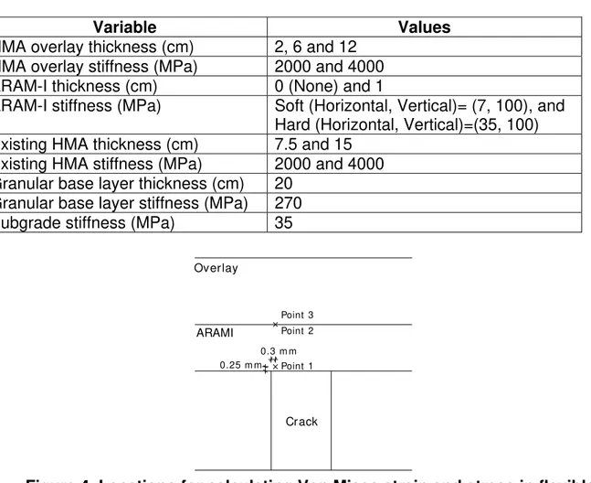
Because the occurrence of reflective cracking is governed by a stress concentration at the crack tip, the mesh size near the crack tip has a great impact on the FEM results, mainly in the vertical direction. As the size of the elements near the crack tip is reduced, both the stress and strain increase dramatically. Thus, to compare the pavement behavior for the different pavement configurations, the Von Mises strain was calculated just above the crack tip at point 1 shown in Figure 4. When an interlayer is used, the Von Mises strain was calculated at points 2 and 3 just at the interface between the ARAM-I and overlay. Von Mises stresses were calculated at the same locations as for the strains.
Table 5. Material properties used in the finite element analysis
Variable Values HMA overlay thickness (cm) 2, 6 and 12
HMA overlay stiffness (MPa) 2000 and 4000
ARAM-I thickness (cm) 0 (None) and 1
ARAM-I stiffness (MPa) Soft (Horizontal, Vertical)= (7, 100), and Hard (Horizontal, Vertical)=(35, 100) Existing HMA thickness (cm) 7.5 and 15
Existing HMA stiffness (MPa) 2000 and 4000 Granular base layer thickness (cm) 20
Granular base layer stiffness (MPa) 270
Subgrade stiffness (MPa) 35
ARAMI
Point 1 0.25 m m
0.3 m m
Crack Overlay
Point 3 Point 2
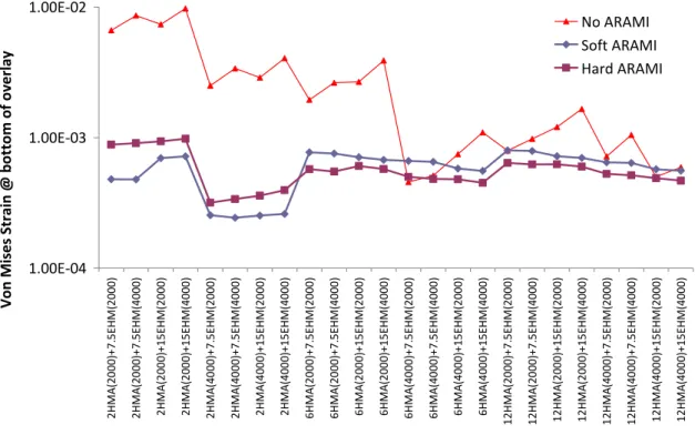
The Von Mises strains obtained with the FEM analysis for the various structures analyzed are shown in Figure 5. The various structures (shown on the x-axis) are indicated by the HMA overlay thickness and its corresponding stiffness, followed by the existing HMA (EHM) thickness and its corresponding stiffness. For example, 2HMA(2000)+7.5EHM(2000) represents the case for the pavement structure with 2 cm of HMA overlay with a stiffness of 2000 MPa, placed over 7.5 cm of existing HMA with a stiffness of 2000 MPa. Figure 5 reveals the following:
• There is a general reduction in Von Mises strain at the bottom of the overlay when ARAM-I is used.
• The reduction in strain level at the bottom of overlay due to ARAM-I is more evident for thin overlays than for thick overlays.
• For thin overlays (2 cm thick), the existing pavement and the stiffness of the overlay do not influence the strain reduction associated with the presence of the ARAM-I.
• For medium thickness overlays (6 cm), the strain reduction is more evident with softer overlays than with stiffer overlays.
• For thick overlays (12 cm), the presence of ARAM-I is beneficial for soft overlays but the benefits are considerably reduced compared to thin overlays. • For thin overlays, the reduction in strain due to the use of ARAM-I can be as
high as 90%, and for medium thick overlays it can reach 80%.
1.00E‐04 1.00E‐03 1.00E‐02
2HMA(20 00)+7 .5 E H M (2 000 ) 2HMA(20 00)+7 .5 E H M (4 000 ) 2 H MA( 2 00 0)+15 E HM(2 000 ) 2 H MA( 2 00 0)+15 E HM(4 000 ) 2HMA(40 00)+7 .5 E H M (2 000 ) 2HMA(40 00)+7 .5 E H M (4 000 ) 2 H MA( 4 00 0)+15 E HM(2 000 ) 2 H MA( 4 00 0)+15 E HM(4 000 ) 6HMA(20 00)+7 .5 E H M (2 000 ) 6HMA(20 00)+7 .5 E H M (4 000 ) 6 H MA( 2 00 0)+15 E HM(2 000 ) 6 H MA( 2 00 0)+15 E HM(4 000 ) 6HMA(40 00)+7 .5 E H M (2 000 ) 6HMA(40 00)+7 .5 E H M (4 000 ) 6 H MA( 4 00 0)+15 E HM(2 000 ) 6 H MA( 4 00 0)+15 E HM(4 000 ) 1 2HMA(20 00)+7 .5 E H M (2 000 ) 1 2HMA(20 00)+7 .5 E H M (4 000 ) 12 HMA( 2 0 0 0 )+15 E H M(2 000 ) 12 HMA( 2 0 0 0 )+15 E H M(4 000 ) 1 2HMA(40 00)+7 .5 E H M (2 000 ) 1 2HMA(40 00)+7 .5 E H M (4 000 ) 12 HMA( 4 0 0 0 )+15 E H M(2 000 ) 12 HMA( 4 0 0 0 )+15 E H M(4 000 ) Pavement Von Mises St ra in @ bo tt o m of over la y
No ARAMI Soft ARAMI Hard ARAMI
Figure 5. Von Mises strain at the bottom of flexible pavement overlay
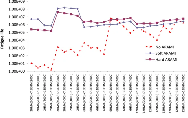
Figure 6. It is obvious that the use of ARAM-I underneath an overlay can extend the life of the overlay significantly.
7. CONCLUSIONS
SAMI-R has consistently been shown to reduce reflective cracking when used as part of preservation and rehabilitation strategies. Field studies as well as accelerated wheel tracking experiments and analytical studies have confirmed the significant contribution of SAMI-Rs in improving pavement life and in minimizing reflective cracking. Finite Element Analysis in this study have validated the outstanding performance of the Composite Layering System with the SAMI-R, and further quantified the benefits of SAMI-R in terms of primary response reduction and in increased pavement life. It was found that, in flexible pavements, generally soft overlays such as asphalt rubber hot mix gap graded (ARHM-G) realize more benefits from interlayers than stiffer overlays such as conventional dense graded hot mixes.
1.00E+00 1.00E+01 1.00E+02 1.00E+03 1.00E+04 1.00E+05 1.00E+06 1.00E+07 1.00E+08 1.00E+09 2HMA(20 00)+7 .5 E H M (2 000 ) 2HMA(20 00)+7 .5 E H M (4 000 ) 2 H MA( 2 00 0)+15 E HM(2 000 ) 2 H MA( 2 00 0)+15 E HM(4 000 ) 2HMA(40 00)+7 .5 E H M (2 000 ) 2HMA(40 00)+7 .5 E H M (4 000 ) 2 H MA( 4 00 0)+15 E HM(2 000 ) 2 H MA( 4 00 0)+15 E HM(4 000 ) 6HMA(20 00)+7 .5 E H M (2 000 ) 6HMA(20 00)+7 .5 E H M (4 000 ) 6 H MA( 2 00 0)+15 E HM(2 000 ) 6 H MA( 2 00 0)+15 E HM(4 000 ) 6HMA(40 00)+7 .5 E H M (2 000 ) 6HMA(40 00)+7 .5 E H M (4 000 ) 6 H MA( 4 00 0)+15 E HM(2 000 ) 6 H MA( 4 00 0)+15 E HM(4 000 ) 1 2HMA(20 00)+7 .5 E H M (2 000 ) 1 2HMA(20 00)+7 .5 E H M (4 000 ) 12 HMA( 2 0 0 0 )+15 E H M(2 000 ) 12 HMA( 2 0 0 0 )+15 E H M(4 000 ) 1 2HMA(40 00)+7 .5 E H M (2 000 ) 1 2HMA(40 00)+7 .5 E H M (4 000 ) 12 HMA( 4 0 0 0 )+15 E H M(2 000 ) 12 HMA( 4 0 0 0 )+15 E H M(4 000 ) Pavement Fatigue li fe
No ARAMI Soft ARAMI Hard ARAMI
8. REFERENCES
ASTM, 2005, ASM International Annual Book of Standards, D 8 Definition, 2005.
Bin, Y., Baigang, C. and Jun, Y., 2009, “Laboratory Simulation of Reflective Cracking by Load,” Proceedings of the AR2009 Conference, Nanjing, China.
Coetzee, N.F. and Monismith, C.L., 1978, “An Analytical Study of the Applicability of a Rubber Asphalt Membrane to Minimize Reflection Cracking in Asphalt Concrete Pavements,” Report to Arizona Refining Company and U.S. Rubber Reclaiming Company, Inc., June.
Chen, N. J., Divito, J. A. and Morris, G. R., 1982, “Finite Element Analysis of Arizona’s Three-Layer Overlay System of Rigid Pavements to Prevent Reflective Cracking”, Association of Asphalt Paving Technologists.
de Laubenfels, L., 1988, “Effectiveness of Rubberized Asphalt in Stopping Reflection Cracking of Asphalt Concrete, “ (Interim Report), California Department of Transportation, FHWA/CA/TL-85/09, January.
Green, E. L. and Tolonen, W. J., 1977, “The Chemical and Physical Properties of Asphalt-Rubber Mixtures”, Report No. ADOT-RS-14 (162) Final.
Greenbook, 2004., Greenbook-Standard Specifications for Public Works Construction, 2004 Edition, Publisher, Building News, Anaheim CA.
MTAG, 2003, “Maintenance Technical Advisor Guide (MTAG),” California Department of Transportation, Sacramento, CA.
Predoehl, Nelson H., 1990, “Performance of Asphalt-Rubber Stress Membranes (SAM) and Stress Absorbing Membrane Interlayers (SAMI) in California.” California Department of Transportation.
Shatnawi, S. and Holleran G., 2003, “Asphalt Rubber Maintenance Treatments in California”, Proceedings, of Asphalt Rubber 2003 Conference, Brasilia, Brazil.
Schnormeier, Russell Howard, 1985, “Fifteen Year Pavement Condition History of Asphalt Rubber Membranes in Phoenix, Arizona.” Published by the Asphalt Rubber Producers Group.
Shirley, E., 1992, “Design Guide for ARHM-GG”, Memorandum, California Department of Transportation, Feb. 28.
Sousa, J. Dr., Pais, J., Way, G., Saim, R. and Stubstad, R. 2002, “A Mechanistic-Empirical Overlay design Method for Reflective Cracking,” Transportation Research Record 1809, TRB National Research Council, Washington D.C., pp. 209-217.
Standard Specifications, 2003, California Department of Transportation, Sacramento, CA.
Van Kirk, Jack, 2003, “Maintenance and Rehabilitation Strategies Using Asphalt Rubber Chip Seals”, Proceedings, Asphalt Rubber 2003 Conference, Brasilia, Brazil, December 2-4.
Van Kirk, Jack, 2006, “Multi-Layer Pavement Strategies Using Asphalt Rubber Binder”, Proceedings, Asphalt Rubber 2006, Palm Springs, California, October 25-27.