*e-mail: [email protected]
Instituto de Química, Universidade Estadual de Campinas, C. P. 6154, 13083-970Universidade Estadual de Campinas, C. P. 6154, 13083-97013083-970 Campinas - SP, Brazil
Effect of Tire Rubber Particles on Crack Propagation in Cement Paste
Nadia Segre*, Claudia Ostertag, Paulo José Melaragno Monteiro
Department of Civil and Environmental Engineering,
University of California at Berkeley, 725 Davis Hall, Berkeley, CA 94720, USA
Received: February 2, 2006; Revised: June 19, 2006
Tire rubber particles (NaOH-treated and untreated) were investigated as possible crack stabilizer and toughness enhancer when added to cement paste through in situ crack propagation measurements using two different types of cement, type I/II and an Interground polypropylene Fiber Cement (IFC). Crack deflection and crack bridging were observed in specimens with untreated rubber in cement type I/II. Crack tip mechanisms associated with crack pinning and crack arrest were present in type I/II cement and IFC with treated rubber particles. Crack tip mechanisms in IFC with treated rubber lead to the increase in CMOD at the ultimate load level. Crack wake mechanisms in IFC with untreated or treated rubber lead to strain hardening and strain softening behavior. Crack wake bridging mechanisms were replaced by multiple cracking mechanisms in the IFC specimens with treated rubber. The IFC specimens with untreated rubber inclusions provided the best results with respect to toughness enhancement.
Keywords: tire rubber, cement composites, crack propagation, toughness
1. Introduction
The ever-increasing volume of used tires in landfills has gener-ated a serious environmental problem. Even after long periods of landfill treatment, tire rubber does not biodegrade, therefore there is a renewed interest in developing alternatives to its disposal. One possible solution is to incorporate tire rubber particles into cement-based materials1-13. Tire rubber particles may have the potential of enhancing the toughness of cement-based materials by interfering with crack propagation processes and activating toughening mecha-nisms commonly observed in brittle matrices reinforced by particles or second-phase inclusions3,7,14-17.
The stress-strain curve of a quasi-brittle material generally con-sists of three regions corresponding to the different mechanisms that control the behavior of the composite. The first region corresponds to the linear elastic response of the composite. The point at which the stress-strain curve becomes nonlinear (bend over point) corresponds to the beginning of cracking extension. The second region, where the strength increases beyond the bend over point up to a maximum, which is the ultimate strength of the composite, is associated with a strain hardening regime and characterizes the ability of the second-phase to stabilize a growing cracking process. The third region, where the composite gradually loses its load carrying capacity, is associated with the strain softening regime. Materials with this type of quasi-brittle behavior exhibit desirable properties such as enhanced flaw tolerance and toughness.
Crack tip and crack wake mechanisms characterize toughening mechanisms in brittle composites. Crack tip mechanisms commonly involve crack-inclusion interactions at the crack tip such as crack pinning, crack bowing between inclusions and crack blunting. Crack wake mechanisms include bridging of crack surfaces by inclusions and in some instances pullout of inclusions from the matrix. The crack wake mechanisms are considered more effective as energy absorbing mechanisms due to their cumulative nature.
Most theoretical and experimental studies on crack propagation and crack/reinforcement interactions consider the reinforcements to
be incorporated into the crack wake by a crack front that has moved in a stable manner passed these reinforcements. The assumption of a stable crack interacting with reinforcements may be valid for compos-ites with high volume fractions of reinforcements. However, at low volume fractions (and hence large spacing between reinforcements) such as in cement-based materials reinforced with rubber particles, the crack may become unstable shortly after initiation before it has interacted with the rubber particles or the interaction being limited to only a few particles. An unstable crack front moving passed rub-ber particles with high crack velocity will require far more bridging ligaments behind the crack tip to slow down its propagation. Special attention has to be given to prevent the crack from becoming unstable before interacting with a certain critical number of inclusions. For toughness enhancement, both crack tip and crack wake mechanisms may play an important role. These mechanisms have to be optimized in order to reduce the crack velocity, allowing rubber particles to be incorporated into the crack wake by a crack front that has moved in a stable manner when passed these particles.
2. Methods
2.1. Specimens preparation
Untreated rubber tire particles of 500 µm maximum size (density: 1.152 ± 0.001 g.cm-3) were supplied by Borcol Industria de Borracha Ltda (Sorocaba/SP, Brazil). The particles were surface treated with saturated NaOH aqueous solution for 20 minutes at room temperature whilst stirring. The mixture was filtered and the rubber was rinsed with water until neutral pH was achieved and allowed to dry at room temperature18. The Interground polypropylene Fiber Cement (IFC) production involves a new technique where polypropylene (PP) fibers (12 mm in maximum length and 18 µm in diameter) are added to the cement clinker during grinding. The intergrinding process allows the fibers to be distributed homogeneously within the cement. The IFC contains 0.3% of polypropylene fibers by weight of cement20. Control specimens and specimens containing 10% (by weight of the paste) of treated or untreated rubber particles were prepared using both the IFC and the ASTM type I/II cement. A water/cement ratio, w/c, of 0.36 was used for all specimens. The polypropylene fiber volume frac-tion in the specimens at the w/c ratio used is only 0.4%. In volume, the amount of rubber in the specimens represents 15%.
The specimens were cast using 50 x 50 x 50 mm steel molds. Two acrylic rods were pre-positioned inside the steel molds in order to obtain the two holes in the specimens necessary to fix the sample in the loading device. The mix was placed in the formwork and compacted on a vibrating table for about 20 seconds. After 28 days of curing at 100% relative humidity, the cubes were cut into compact tension specimens with a width of 50 mm and a thickness of 6 mm. A notch length of 25 mm was cut in all specimens using a saw blade of 0.3 mm thickness. The specimens surface were successively polished with 38 µm SiC powder, 12 µm, 9 µm and 3 µm Al2O3 powder to ensure uniform thickness and smooth surfaces to facilitate the crack propagation observations under the microscope.
2.2. In situ crack propagation measurements
The loading device designed for crack propagation measurements is shown in Figure 1. It uses a piezoelectric transducer for load trans-fer. The piezoelectric transducer is placed between two pivot arms and, after being activated by a high voltage amplifier, delivers opening forces to the compact tension specimen through the loading arms. The input voltage was computer controlled. A load cell is placed in one of the loading arms and monitors the applied load20,21.
The crack mouth opening displacement (CMOD) was monitored through a MTS clip gage mounted on the specimen. The loading de-vice was staged under an optical microscope equipped with a video camera connected to a TV screen and a video recorder.
The loading fixture allows testing to be performed under dis-placement control. A small disdis-placement rate of 1 µm/s was chosen for all specimens to be able to observe the crack tip and crack wake mechanisms while loading. The crack propagation is continuously monitored and recorded on video up to specimen failure.
3. Results
3.1. ASTM Type I/II cement paste containing
tire rubber particles
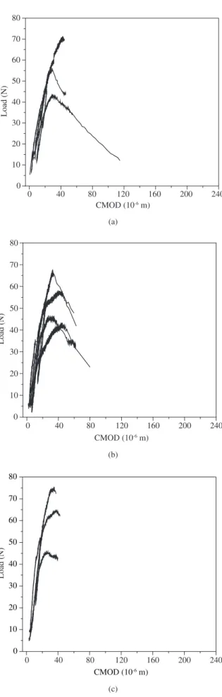
Compact tension tests were performed on Type I/II cement paste specimens containing untreated or treated tire rubber particles to gain information on their crack propagation processes. Load as a function of crack mouth opening displacement (CMOD) for these specimens and the control are shown in Figure 2. Beyond the ultimate load, a
continuous strain softening curve could not be obtained. The deviation from linearity in the load as a function of CMOD curves indicates the extension of the crack from the notch tip. Crack initiation from the notch occurred, in average, at similar load levels for the control and specimens with untreated rubber. For the specimens with treated rubber, known for their better adhesion to the cement matrix18, a more pronounced strain hardening regime was observed in the load vs.
CMOD plots (Figure 2b). The load level at which the crack initiated from the notch tip was on average reduced compared to the control specimens. The cement paste matrix seemed to be weakened by the treated rubber particles.
Box plots were built to gain an overview of data from a statistical perspective. A box plot is an effective visual representation of both central tendency and dispersion. Box shows 50% of the data, the small square indicates the average, the median is shown as a line across the box (or on its horizontal bounds) and the vertical line contains the other 50% of the data and the minimum and maximum data values on its edges. The length of the vertical lines indicates visually how far from the middle of the distribution the extreme values are.
Figure 3 shows box plots of ultimate load and toughness, which is proportional to the area under the entire load-CMOD curves, obtained for the specimens tested. Variability in ultimate load, characterized by the boxes sizes and vertical lines lengths, is common to all sets of specimens, with or without rubber particle. No improvement in strength was observed for the specimens that contain rubber parti-cles, compared to the control. On the other hand, higher toughness is observed for the specimens containing treated rubber particles and a tendency to higher toughness for the specimens with untreated rubber, when compared to the control specimens. Even though no statistical difference, in average, for toughness is observed between the specimens containing rubber, the composites with treated rubber showed less scattered values when compared to the composites with untreated rubber.
Figure 2. Load vs. crack mouth opening displacement curves for ASTM type I/II Portland cement paste specimens. a) untreated rubber particles; b) treated rubber particles; and c) control specimens.
(a)
0 40 80 120 160 200 240
0 10 20 30 40 50 60 70 80
Load (N)
CMOD (10-6 m)
(b)
0 40 80 120 160 200 240
0 10 20 30 40 50 60 70 80
Load (N)
CMOD (10-6 m)
(c)
0 40 80 120 160 200 240
0 10 20 30 40 50 60 70 80
Load (N)
CMOD (10-6 m)
control treated untreated 10
20 30 40 50 60 70 80
Ultimate load (N)
Figure 3. Box plots for ultimate load and toughness for ASTM type I/II Portland cement paste specimens control and containing treated or untreated rubber particles.
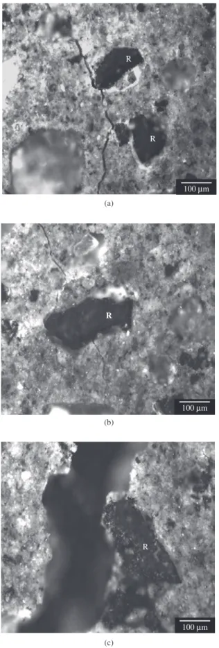
manner without considerable crack deflection and the crack became unstable after small increments of crack extension. Crack/rubber par-ticle interactions shown in Figure 4 were observed in the specimens with untreated tire rubber particles. After encountering the rubber particles, the crack was deflected (i.e., changed in fracture path) by the rubber particles (Figure 4a). Rubber bridging sites as shown in Figure 4b, where rubber particles bridge the crack surfaces, were also observed. The micrographs of the crack/rubber interactions in Figure 4a, b could only be obtained after the crack tip was already located far beyond the rubber particles. Pull-out of a rubber particle is shown in Figure 4c. In–situ crack/rubber interactions could not be observed in these specimens.
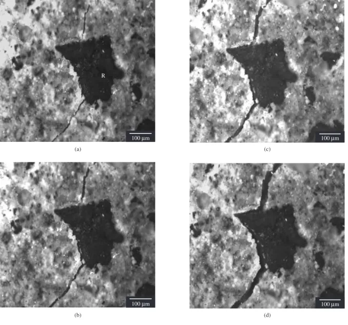
For the specimens with treated rubber, the in-situ crack propaga-tion measurements revealed that the crack was attracted by the rubber particles. The crack deflected from its original path (Figure 5a, b), where original path would have been from the top to the bottom of the micrograph, to interact with the rubber particles. This attraction allowed a more effective crack/rubber interaction compared to the
(a)
control treated untreated 0.000
0.001 0.002 0.003 0.004 0.005 0.006 0.007
T
oughness (N.m)
Figure 4. Crack/rubber interaction in ASTM type I/II Portland cement paste specimens with untreated rubber particles. The crack propagation occurs from top to bottom of the micrographs. a) the crack is deflected by the untreated rub-ber particles; b) the crack is bridged by the rubrub-ber particle; and c) pull-out of a rubber particle, after specimen failure. Letter R indicates a rubber particle.
(a)
R
R
100Mm
(b) R
100Mm
(c)
untreated rubber particles. Tensile stresses in the matrix due to an elastic mismatch between the rubber particles and the matrix may be responsible for the observed load reduction at crack initiation and for attracting the crack towards the rubber particles.The crack after being attracted by the rubber particles incorporates them in its wake. Crack pinning by rubber particles was also observed. The rubber particles eventually debond along both sides of the rubber/matrix interface (Figure 5c, d) and may stretch between the crack surfaces before being pulled out of the matrix. These crack/rubber particle interactions are responsible for the more prominent strain hardening behavior.
3.2. IFC paste containing tire rubber particles
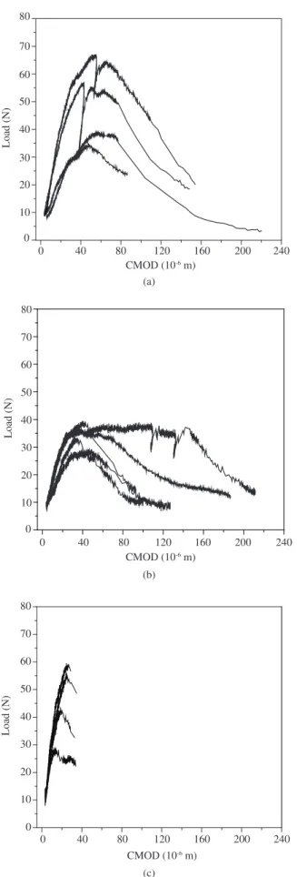
The load vs. CMOD plots for the IFC paste specimens control and containing treated or untreated rubber particles are shown in Figure 6. Strain hardening and pronounced strain softening behavior was observed for the treated and untreated rubber IFC specimens, compared to the control. Similar to the type I/II cement specimens with treated rubber particles the load required for crack initiation from the notch was reduced compared to that of the control and with untreated rubber specimens. However, an increase in CMOD at the ultimate load level was observed. Box plots of ultimate load and toughness obtained for these specimens are shown in Figure 7. Although less scattered, lower values of ultimate load are observed for specimens containing treated rubber, compared to the control and to the specimens with untreated rubber. A prominent toughness enhancement is observed for the specimens with rubber, compared to the control. A tendency to higher toughness is observed for the speci-mens containing untreated rubber, when compared to the specispeci-mens with treated rubber. On the other hand, a higher number of data points are observed in the strain softening region of the curves obtained for the specimens containing treated rubber (Figure 6b) indicating more stable crack propagation.
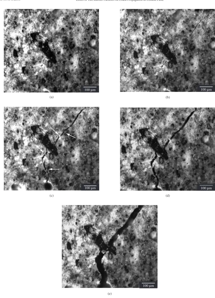
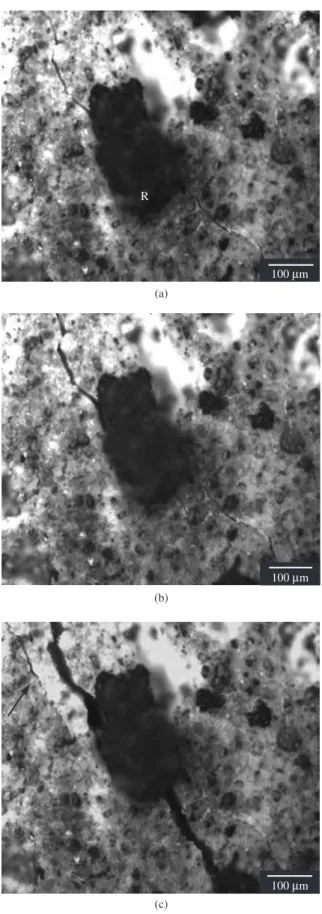
After failure, all specimens remained unbroken. The IFC control specimens revealed intact polypropylene fibers bridging the crack surfaces from the notch tip to the end of the specimen. For the rubber specimens, no cracks could be detected with the naked eye or in the optical microscope unless the specimens were reloaded. The untreated rubber particles constituted bridging sites in the crack wake. A rub-ber-bridging site close to the crack tip and in the wake of the crack is shown in Figure 8 at different applied load levels. Due to stable crack propagation this crack-rubber interaction could be observed from their early stage of development in close proximity to the crack tip until their disintegration at applied displacements close to failure. Figure 8a reveals the bridging site in its early stage with the crack tip just ahead of the rubber particle. With increasing displacements, the crack opens and reveals the polypropylene fibers (indicated by arrows in Figure 8c) bridging the crack surfaces. The micrograph shown in Figure 8e was taken after failure.
Crack pinning by treated rubber particles was also observed, as shown in Figure 9. For treated rubber particles in IFC matrix, the ma-jority of crack/rubber interactions lead to crack detention at the rubber particles. The initial crack did not remain the dominant crack up to failure as shown in Figure 10. Frequently secondary cracks initiated at the bridging sites at higher applied load levels (Figure 10b) and one of these cracks became the dominant crack as shown in Figure 10c, which reveals the bridging site after failure. On the left of the bridg-ing site, an additional microcrack has formed (indicated by arrow in Figure 10c) probably due to stress redistribution.
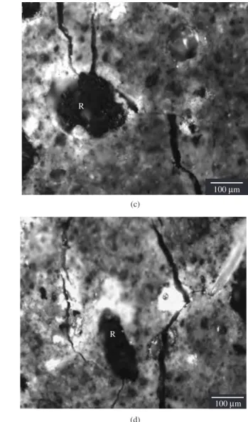
The crack is attracted by the rubber particles (Figure 11a), like in the specimens with treated rubber in cement type I/II. The crack instead of propagating from top to bottom (i.e. perpendicular to the applied tensile stress) it deflects to the left in order to interact with the rubber particle. Various types of secondary cracks that form in
R
R
R R
100Mm
R
R
R R
100Mm
100Mm R
R
R
R
R
100Mm
(a)
(b)
(c)
(d)
Figure 5. Crack/rubber interaction in ASTM type I/II Portland cement paste specimens with treated rubber particles. The crack propagation occurs from top to bottom of the micrographs. In a,b) the crack is attracted by the treated rubber particles and incorporates them in its wake. The crack is deflected from its original path (the original path being from top to bottom of micrograph) in order to interact with the rubber particles; and c,d) rubber particle de-bonded along both sides of the rubber/matrix interface and is being stretched between crack surfaces. Micrographs c and d were taken after failure of the specimen. Letter R indicates a rubber particle.
close proximity to the rubber bridging sites are shown in Figure 11. The crack wake bridging mechanisms were replaced by multiple cracking mechanisms, which lead to a toughness enhancement at the expense of weakening the matrix and reducing the hardness. The multiple secondary microcrack formations are responsible for the increase in CMOD at ultimate load level observed in Figure 6. The multiple cracking mechanisms may also be accountable for the reduced variability in ultimate load values shown in Figure 7. All treated rubber specimens failed in a very narrow range of load levels,
contrary to all other specimens, which revealed a large variability in crack initiation and ultimate loads.
4. Discussion
0 40 80 120 160 200 240 0
10 20 30 40 50 60 70 80
Load (N)
CMOD (10-6 m)
(a)
0 40 80 120 160 200 240
0 10 20 30 40 50 60 70 80
Load (N)
CMOD (10-6 m)
(b)
0 40 80 120 160 200 240
0 10 20 30 40 50 60 70 80
Load (N)
CMOD (10-6 m)
(c)
Figure 6. Load vs. crack mouth opening displacement curves for Interground Fiber Cement (IFC) paste specimens. a) untreated rubber particles; b) treated rubber particles; and c) control specimens.
control treated untreated 10
20 30 40 50 60 70 80
Ultimate load (N)
(a)
control treated untreated 0.000
0.001 0.002 0.003 0.004 0.005 0.006 0.007
T
oughness (N.m)
(b)
Figure 7. Box plots for ultimate load and toughness for Interground Fiber Cement (IFC) paste specimens control and containing treated or untreated rubber particles.
(a) (b)
R
100Mm 100Mm
(c) (d)
100Mm 100Mm
100Mm
(e)
R
100Mm
(a)
100Mm
(c)
100Mm
(b)
100Mm
(d)
Figure 9. Crack/rubber interaction in IFC paste specimens with treated rubber particles at different applied load levels: a) pinning point at 40% of ultimate load; b) pinning point at 50% of ultimate load; c) close to peak load; and d) after peak load. Letter R indicates a rubber particle.
In the absence of effective crack tip mechanisms, stable crack propagation can only be assured, and hence toughness increased, if additional bridging ligaments are incorporated into the wake of the crack. This can be accomplished by either increasing the volume frac-tion of the rubber particles or, as was done in this study, by using IFC as the matrix. The toughness enhancement observed in IFC-rubber specimens, far exceeding the toughness enhancement in type I/II ce-ment-rubber specimens, is attributed to the polypropylene, PP, fibers in IFC. The reduction in crack velocity due to the PP-fibers allows the rubber particles to be incorporated into the crack wake by a crack front that has moved in a stable manner when passed these reinforce-ments, activating the bridging mechanisms at relatively short crack lengths. It is worth noting here, that the IFC control specimens did not exhibit toughness enhancement due to the PP-fibers compared to Type I/II cement control specimens (Figures 3 and 7).
Crack tip mechanisms were present in specimens with treated rubber particles, in type I/II cement and IFC. The crack was attracted
by the treated rubber particles leading to crack pinning and crack arrest. Crack pinning in type I/II cement-treated rubber specimens slowed down the crack velocity even before considerable crack wake mechanisms were activated. The slow down in crack propagation is due to the crack front bowing out between the pinning positions and thereby absorbing energy from the crack tip due to the increase in crack front length and due to the creation of new surfaces14. This in-crease in energy contributes to toughness enhancement. The observed strain hardening behavior enhancement in Figure 2b is associated with crack wake mechanisms such as successive debonding of the rubber/cement paste interface, followed by bridging and stretching of the rubber particles between the crack surfaces.
R
100Mm
(a)
(b)
100Mm
(c)
Figure 10. Crack/rubber interaction in IFC paste specimens with treated rubber particles at different applied load levels. a) rubber particle is bridging the crack surfaces; b) at higher applied load, a secondary crack initiates in close vicin-ity to the rubber particles due to high frictional tractions at the rubber/matrix interface; and c) rubber particle after failure of the specimen; the initial crack did not remain the dominant crack at failure; additional microcracks opened up to the left of the rubber particle. Letter R indicates a rubber particle.
wake of the crack (as was observed for the treated rubber particles in type I/II cement), the pinning lead to crack arrest and stress redis-tribution which caused secondary cracks to form in close vicinity to the crack pinning sites. In this case, crack tip mechanisms prevented crack wake mechanisms such as rubber bridging and pullout from developing. Hence, less prominent strain hardening could be observed in these specimens. The increase in CMOD at the ultimate load level (Figure 6b) is associated with the multiple cracking mechanisms. The reduction in crack velocity due to the polypropylene fibers in IFC may have modified the deformation characteristics of the treated rubber particles.
5. Conclusions
In situ crack propagation measurements were performed on ce-ment paste specimens containing untreated or treated tire rubber to investigate the crack/rubber interactions and the underlying tough-ening mechanisms. The effect of matrix on crack propagation was investigated using two different types of cement, the common type I/II Portland cement and an Interground Fiber Cement (IFC).
The toughness of cement paste with rubber inclusions was influ-enced by both crack tip and crack wake mechanisms. The existence or absence of crack tip and/or crack wake mechanisms depends on the adhesion between the rubber particles and the cement paste and the type of cement used (type I/II or IFC). Crack deflection and crack bridging were observed in specimens with untreated rubber in ce-ment type I/II. These mechanisms however did not lead to significant toughening enhancement due to unstable crack propagation prior and during crack/rubber particle interaction. Crack tip mechanisms were observed for treated rubber-IFC and treated rubber-type I/II cement specimens. Crack tip mechanisms in IFC with treated rubber lead to the increase in CMOD at the ultimate load level. Crack wake mechanisms in IFC with untreated or treated rubber lead to strain hardening and strain softening behavior, compared to the control. The effectiveness of the crack wake mechanisms was dependent on the crack velocity encountered by the rubber particles while interacting with the propagating crack. Crack wake bridging mechanisms were replaced by multiple cracking mechanisms in the IFC specimens with treated rubber. The IFC specimens with treated rubber inclusions showed the most stable crack propagation and the IFC specimens with untreated rubber inclusions provided the best results with respect to toughness enhancement.
Acknowledgments
N. Segre wishes to thank FAPESP-Brazil (grant 99/10022-2) and NSF (Award CMS-9812757) for financial support. Thanks are also due to Prof. Dr. José de Anchieta Rodrigues (DEMa, UFSCar, Brazil) for the valuable suggestions.
References
1. Lee BI, Burnett L, Miller T, Postage B, Cuneo J. Tyre rubber/ce-ment matrix composites. Journal of Materials Science Letters. 1993; 12(13):967-968.
2. Eldin NN, Senouci AB. Observations on rubberized concrete behavior. Cement, Concrete and Aggregates. 1993; 15(1):74-84.
3. Toutanji HA. The use of rubber tire particles in concrete to replace mineral aggregates. Cement and Concrete Composites. 1996; 18(2):135-139.
4. Raghavan D, Huynh H, Ferraris CF. Workability, mechanical proper-ties and chemical stability of a recycled tyre rubber-filled cementitious composite. Journal of Materials Science. 1998; 33(7):1745-1752.
5. Li Z, Li F, Li JSL. Properties of concrete incorporating rubber tyre par-ticles. Magazine of Concrete Research. 1998; 50(4):297-304.
R
R
100Mm
(a)
R
100Mm
(c)
R
100Mm
(b)
R
100Mm
(d)
Figure 11. a) Crack being attracted by the treated rubber particle in IFC paste matrix; b-d) Various types of secondary cracks that form in close vicinity to bridging sites in IFC paste specimens with treated rubber particles. Letter R indicates a rubber particle.
6. Bignozzi MC, Saccani A, Sandrolini F. New polymer mortars contain-ing polymeric wastes. Part 1. Microstructure and mechanical properties. Composites A. 2000; 31(2):97-109.
7. Raghavan D. Study of rubber-filled cementitious composites. Journal of Applied Polymer Science. 2000; 77(4):934-942.
8. Nehdi M, Khan A. Cementitious composites containing recycled tire rubber: An overview of engineering properties and potential applications. Cement, Concrete and Aggregates. 2001; 23(1):3-10.
9. Bignozzi MC, Saccani A, Sandrolini F. New polymer mortars containing polymeric wastes. Part 2. Dynamic mechanical and dielectric behaviour. Composites A. 2002; 33(2):205-211.
10. Hernandez-Olivares F, Barluenga G, Bollati M, Witoszek B. Static and dynamic behaviour of recycled tyre rubber-filled concrete. Cement and Concrete Research. 2002; 32(10):1587-1596.
11. Siddique R, Naik TR. Properties of concrete scrap-tire rubber: an over-view. WasteManagement. 2004; 24(6):563-569.
12. Huang B, Li G, Pang S-S, Eggers J. Investigation into waste tire rub-ber-filled concrete. Journal of Materials in Civil Engineering. 2004; 16(3):187-194.
13. Segre N, Joekes I, Galves AD, Rodrigues JA. Rubber-mortar composites: Effect of composition on properties. Journal of Materials Science. 2004; 39(10):3319-3327.
14. Lange FF. The interaction of a crack front with a second phase dispersion. Philosophical Magazine 1970; 22(179):983-992.
15. Green DJ. Fracture toughness predictions for crack bowing in brittle particulate composites. Journal of the American Ceramic Society. 1983; 66(1):C4-C5.
16. Evans AG. The strength of brittle materials containing second-phase dispersions. Philosophical Magazine. 1972; 26(6):1327-1344.
17. Ostertag CP. In-situ crack propagation in pressureless sintered fiber reinforced composites. Composites Engineering. 1995; 5(10-11):1317-1329.
18. Segre N, Joekes I. Use of tire rubber particles as addition to cement paste. Cement and Concrete Research. 2000; 30(9):1421-1425.
19. Segre N, Monteiro PJM, Sposito G. Surface characterization of recycled tire rubber to be used in cement paste matrix. Journal of Colloid and Interface Science. 2002; 248(2):521-523.
20. Ostertag CP, Yi CK, Vondran G. Tensile strength enhancement in Inter-ground Fiber Cement composites. Cement and Concrete Composites. 2001; 23(4-5):419-425.