Faculdade de Engenharia da Universidade do Porto
Additive manufacturing of custom-fit orthoses for
the upper limb
Ana Sofia Teixeira de Jesus Faria
Dissertation carried out under the
Integrated Master in Bioengineering
Biomedical Engineering
Supervisor: Professor José Domingos Santos, PhD
Co-supervisor: Margarida Machado, PhD
ii
iii
Abstract
Orthoses are medical devices used to support weak or ineffective joints or muscles. Regarding the upper limb, particularly the wrist joint, this is a complex and delicate structure that is prone to several types of injuries, where the use of orthotic devices are commonly prescribed as a complement to therapy. The available orthoses can be considered as pre-fabricated, assuming generic sizes for all patients, or custom-made by a specialized technician. Traditional fabrication methods for custom-made orthoses are time and resource consuming and highly skill dependent, which doesn’t always translate in the best possible fit. Therefore, factors like discomfort, hygiene and aesthetics influence the acceptance and correct wear of the orthosis, which often fails.
It is important to consider an aging global population, and the increased demand that represents to healthcare. In Orthotics, the rise of diagnoses of degenerative joint diseases is expected as one of the consequences of this aging, leading also to a growth on the market for orthoses. New solutions are therefore needed in order to answer this demand, not only in quantity, but also in quality, comfort and design.
This work is intended to explore and validate a digital methodology for the fabrication of custom-fit wrist orthoses. Computer Aided Engineering (CAE) tools are used, starting with the acquisition of the anatomical surface of the upper limb through tridimensional digitalization (3D scanning) to obtain a digital model of the reference arm. The model for the orthosis is then obtained by Computer Aided Design (CAD) using SolidWorks. Structural viability of the design is studied through Finite Element Analysis (FEA) to guarantee the best possible mechanical features, and topological optimization is achieved by mass removal. Finally, Additive Manufacturing (AM) technologies are explored to obtain prototypes, and a comparative study of different processes is performed.
The results of this work support the adoption of such methodology as a potential option to produce customized orthoses. Besides being able to provide a more comfortable, hygienic and aesthetically pleasing solution for wrist orthoses, this methodology is capable of meeting the individual needs of the patient thus providing personalized healthcare.
v
Resumo
As ortóteses são dispositivos médicos usados para suportar articulações ou músculos fracos ou ineficazes. No que toca ao membro superior e particularmente à articulação do pulso, esta é uma estrutura complexa e delicada que está sujeita a vários tipos de lesões, e onde o uso de ortóteses é comumente indicado como um complemento à terapia. As ortóteses disponíveis podem ser consideradas como pré-fabricadas, assumindo tamanhos genéricos para todos os pacientes, ou feitas por medida por um técnico especializado. Os métodos tradicionais para fabricação de ortóteses por medida consomem tempo e recursos, e são altamente dependentes da habilidade do técnico, nem sempre garantindo o melhor ajuste possível. Assim, fatores como o desconforto, higiene e estética influenciam a aceitação e o uso correto da ortótese, o que normalmente falha.
É importante considerar uma população global em envelhecimento e o aumento das exigências que isso representa para os cuidados de saúde. Na Ortopedia, o aumento de diagnósticos de doenças degenerativas das articulações é esperado como uma das consequências deste envelhecimento, levando também a um crescimento no mercado das ortóteses. Novas soluções serão precisas e modo a responder a esta exigências crescentes, não só em quantidade mas também em qualidade, conforto e design.
Este trabalho pretende explorar e validar uma metodologia digital para o fabrico de ortóteses feitas por medida para o pulso. São utilizadas ferramentas de Engenharia Assistida por Computador, começando pela aquisição da superfície anatómica do membro superior através de uma digitalização tridimensional para obter um modelo digital do braço de referência. O modelo da ortótese é então obtido através de Desenho Assistido por Computador, usando o SolidWorks. A viabilidade estrutural do design é estudada usando métodos de Análise de Elementos Finitos de forma a garantir as melhores propriedades mecânicas possíveis, e uma otimização topológica é feita através de remoção de massa. Finalmente, tecnologias de Fabrico Aditivo são exploradas de modo a obter protótipos e um estudo comparativo de diferentes processos é feito.
Os resultados deste trabalho suportam a adoção da metodologia proposta como uma potencial opção para produzir ortóteses por medida. Para além de ser capaz de providenciar uma solução mais confortável, higiénica e esteticamente agradável, esta metodologia é capaz
vi
de ir de encontro às necessidades individuais de cada paciente, fornecendo um cuidado de saúde personalizado.
vii
Acknowledgements
Gostaria de começar por agradecer ao prof. José Domingos Santos por me ter aberto as portas a este tema e por me ter ajudado a orientar este trabalho, partilhando sempre comigo o seu entusiasmo. Este trabalho não seria possível sem a colaboração do INEGI, ao qual agradeço desde já a oportunidade e também ao projeto de investigação que o suportou, a operação NORTE-01-0145-FEDER-000022 – SciTech – Science and Technology for Competitive and
Sustainable Industries, cofinanciada pelo Programa Operacional Regional do Norte
(NORTE2020) através do Fundo Europeu de Desenvolvimento Regional (FEDER).
À Doutora Margarida Machado, por todo o apoio, interesse e horas passadas comigo a procurar fazer mais e melhor. A sua dedicação, sempre incansável, foi sem dúvida uma motivação muito importante que contribuiu para o sucesso deste trabalho.
Agradeço ainda a todos os colaboradores do INEGI que me ajudaram, em especial à Mafalda Couto, ao Tiago Guimarães e ao Isaac Ferreira e também ao prof. Jorge Belinha, à fisioterapeuta Fátima Dória, à Engª. Ana Brandão e à Cristina.
Estes últimos anos não teriam sido os mesmos sem o meu grupo de amigos, ao qual agradeço por todas as histórias, gargalhadas e aventuras que sem dúvida tornaram o meu percurso inesquecível. À Madalena, o meu braço direito desde o início, um obrigado muito especial, e à sua família, por me fazerem sempre sentir em casa.
Quero ainda agradecer à Tuna Feminina de Engenharia, que providenciou a banda sonora dos meus anos de faculdade, pela música, vivências e amizades, e por me ensinar um pouco daquilo que não se aprende nas salas de aula.
Por fim, agradeço à minha família, particularmente ao meu irmão e aos meus pais, que apesar de longe sempre me deram todo o apoio possível e imaginário e que sempre acreditaram em mim, às vezes mais do que eu.
ix
“Adversity introduces a man to himself.”
xi
Contents
Introduction ... 1
1.1 - Context and motivation ... 1
1.2 - Literature review ... 2
1.3 - Objectives ... 6
1.4 - Contributions ... 6
1.5 - Document structure ... 7
Clinical Background ... 9
2.1 - Anatomy and biomechanics of the hand and wrist ... 9
2.2 - Orthotics in rehabilitation ... 16
Digital Tools and Methods ... 27
3.1 - Anatomical data acquisition ... 27
3.2 - Computer Aided Design ... 30
3.3 - Computer Aided Engineering... 31
3.4 - Additive Manufacturing technology ... 32
3.5 - Engineering-based approach for fabrication of orthoses ... 35
Conceptual Design ... 37 4.1 - Concept generation ... 37 4.2 - Designing for AM ... 42 4.3 - Orthosis modelling... 44
Abstract ... iii
Resumo ... v
Acknowledgements ... vii
Contents ... xi
List of Figures ... xiii
List of Tables ...xvii
Abbreviations ... xix
Chapter 1 ... 1
Chapter 2 ... 9
Chapter 3 ... 27
xii
Mechanical Design ... 55
5.1 - Numerical model validation ... 55
5.2 - Structural analysis ... 58 5.3 - Design optimization ... 61 Additive Manufacturing ... 65 6.1 - First prototype ... 65 6.2 - Second prototype ... 67 6.3 - Third prototype ... 69 6.4 - Comparative study ... 71
Conclusions and Future Work ... 73
Chapter 5 ... 55
Chapter 6 ... 65
Chapter 7 ... 73
References ... 75
Appendix A ... 79
Appendix B ... 87
Appendix C ... 89
xiii
List of Figures
Figure 1.1 – Available 3D printed casts and orthoses. A: Osteoid arm cast [17]. B: Cortex arm cast [18]. C: Hashcast [19]. D: Xkelet arm cast [20]. E: moldable wrist orthosis by Zdavprint [27]. F: flat, molded and with added Velcro straps moldable wrist orthosis by Singh [22]. G: Novacast [24]. H: 3D printed thumb orthosis by ActivArmor [25]. I: wrist orthosis by Younext [26]. ... 4 Figure 1.2 – Wrist orthoses developed by Paterson et al. A: wrist orthosis, SL build with
showing support structures [2]. B: different pattern approaches to a wrist orthosis [3]. C: multimaterial construction to allow cushioning of bony prominences [3]. ... 5 Figure 2.1- A: bones of the right hand, dorsal view [32]. B: skeletal arches of the hand [1].
C: carpal tunnel: space between concave carpus and transverse retinacular ligament, enclosing the median nerve and flexor tendons of the fingers [31]. ... 10 Figure 2.2 - Joints of the carpus [31]. ... 11 Figure 2.3 – Palmar view of the ligaments of the left wrist and hand [31]. ... 12 Figure 2.4 - Movements of the hand and forearm. A: forearm pronation and supination. B:
radial and ulnar deviation of the hand. C: wrist flexion and extension. D: flexion, extension and hyper-extension of finger related to MCP joint. E: fingers abduction and adduction (adapted from [37]). ... 13 Figure 2.5 – Carpal tunnel syndrome: the median nerve is compressed at the wrist, resulting
in numbness or pain in the thumb, index, middle and ring fingers [42]. ... 15 Figure 2.6 – Comparison between normal and arthritic wrist and hand. Diseased joints are
inflamed and damaged [44]. ... 16 Figure 2.7 – ASHT’s Splint Classification System (adapted from [49]). ... 18 Figure 2.8 - Proximal interphalangeal (PIP) joint orthoses with different purposes. A: PIP
immobilization orthosis. B: PIP flexion mobilization orthosis. C: PIP extension orthosis [49]. ... 19 Figure 2.9 - Choices of orthotic designs. A: static wrist immobilization orthosis [54]. B:
serial static IP extension mobilization orthosis [49]. ... 20 Figure 2.10 - Choices of orthotic designs. A: dynamic MCP extension orthosis [58]. B: static
progressive PIP extension orthosis [59]. ... 21 Figure 2.11 – Traditional processes for fabrication of orthoses. A: vacuum press for foot
orthoses [60]. B: molding of a polypropylene AFO through a suction cone [61]. C: thermoplastic (Multicast thermoplastic, composed of polycaprolactone and
xiv
polyurethane) sheet heated in water bath. D: molding of the material to the patient’s
arm [62]. ... 22
Figure 2.12 – Workflow of the traditional method for building orthoses (adapted from [2]). . 23
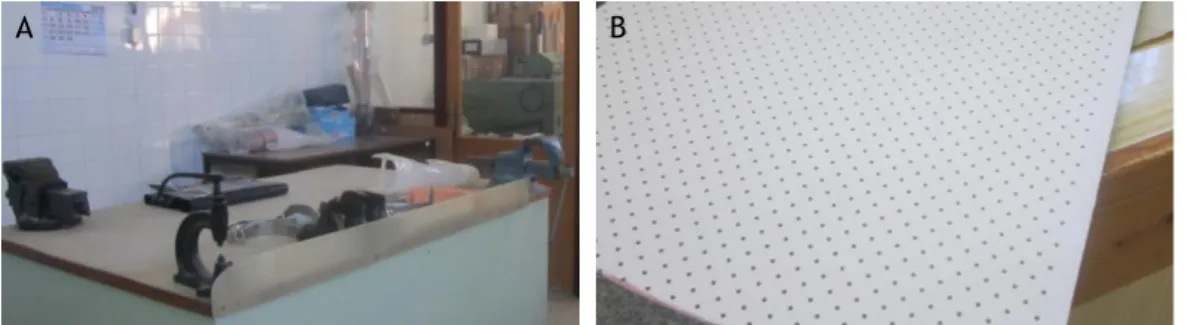
Figure 2.13 – A: workstation for orthosis fabrication with two visible AFOs. B: 3mm thick perforated thermoplastic material used for orthoses. ... 24
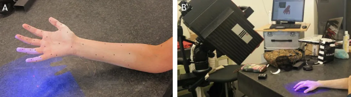
Figure 3.1 – Initial setup for 3D scanning of the reference arm. A: applied powder to the skin and markers. B: setup for initial test. ... 28
Figure 3.2 - 3D Scan of hand and forearm. A C: position of equipment for superior surface data acquisition. D: Real time software reconstruction. ... 29
Figure 3.3 – Obtaining the plaster cast model of the hand. A: Pouring the alginate mix into the plastic container, with the hand in position. B: Pouring the plaster mix into the mold. C: removing the solidified alginate and revealing the solidified plaster. D: Plaster model of the hand, palmar view. E: Plaster model of the hand, dorsal view. ... 30
Figure 3.4 – Model of scanned arm. A: palmar and dorsal views of the imported mesh from 3-matic to MeshMixer; gaps and overlaps are still visible through the faulty edges (blue). B: palmar view of the final model and corresponding dimensions (147.06x54.31x303.65 mm). C: dorsal view of the final reconstructed model ... 31
Figure 3.5 - Liquid/solid/powder based classification of AM processes [80]. ... 33
Figure 3.6 - Illustration of Stereolithography setting [82]. ... 34
Figure 3.7 - Illustration of Fused Deposition Modelling setting [83]. ... 34
Figure 3.8 – Workflow for the followed approach for fabrication of custom-fit orthoses. ... 35
Figure 4.1 – Joints and flexion creases of the hand [88]. ... 38
Figure 4.2 – Dorsal and volar views of the bony prominences of the hand [88]. ... 39
Figure 4.3 – First class lever example on a wrist neutral immobilization splint. A represents the axis at the wrist, R the hand weight or resistance and F the counterforce provided by the forearm [1]. ... 39
Figure 4.4 – Printing results of the “YHT” rule. The “H” and “T” shapes present some drooped filaments due to the lack of support material [89]. ... 42
Figure 4.5 – Automatically generated supports on MeshMixer with a 45º angle threshold for different shapes. ... 43
Figure 4.6 – STL vs CAD format of a doughnut-shaped model. X represents the CAD model surface, and a,b and c represent the edges of the triangular representation of the STL model [93]. ... 45
Figure 4.7 – First approach for CAD modelling. A: intersecting planes with the STL imported model. B: resulting contours. C: resulting surface after loft procedure, with a visible gap near the thumb area. ... 46
Figure 4.8 – Obtaining a shell model for the reference arm. A: selected surface. B: 0.5mm offset surface. C: inferior view of the 0.5mm offset surface. D: inferior view of the second offset surface, 3mm away from the first one. E: inferior view of the connected surfaces/solid model. ... 46
xv
Figure 4.9 – CAD model obtained through the conversion of the STL file using Geomagic for SolidWorks. ... 47 Figure 4.10 – Obtaining the shape of a wrist orthosis. A: reference lines for splitting the
shell. B: resulting body after splitting. ... 47 Figure 4.11 – Designing a two part orthosis model. A: sketched path and profile for the hole
on a section view of the model. B: outline of the resulting holes along the model. C: sketch and respective dimensions used for splitting the body. D: resulting extruded surface, used to split the body in two. ... 48 Figure 4.12 – Fitting part details. A: sketch on cut surface for and elliptical groove/boss.
B: resulting groove in bottom part. C: resulting boss on top part. D: Detail of the fitting of the boss into the groove; fitting of the puzzle-like protuberances is also visible. ... 49 Figure 4.13 – Rendered images of the orthosis model. A, B: Positioning the top and bottom
parts on the arm. C, D: Assembled parts and fitting on the arm. ... 49 Figure 4.14 – Result of the applied Voronoi pattern on the reference arm surface, using
MeshMixer. ... 50 Figure 4.15 – Designing the tear-shaped material removal cells. A: right, middle and left
sketches, manually disposed and with consideration of the border lines. B: performing an extruded cut on the left side, using a guideline (blue) for direction. ... 51 Figure 4.16 – Final mass reduction models. A: rendered image (using SolidWoks) of the
regular distribution lozenge cell on the reference arm. B: top and bottom MeshMixer view of the non-regular distribution lozenge cell. C: top and bottom MeshMixer view of the tear cell. D: top and bottom MeshMixer view of the almond cell. ... 51 Figure 4.17 – Second version of the non-regular distribution lozenge cell. A: new enclosure
method between the fingers, following the same pin and hole approach as the laterals. B: added grooves next to the holes extremities. C: MeshMixer view of the top and bottom parts assembly. D, F: Rendered image (using SolidWorks) of the new orthosis version on the reference arm. ... 52 Figure 4.18 – Increasing the radius in some of the lozenge cells on the third model version.
... 53 Figure 5.1 – Setup for wrist force measurement using a dynamometer. ... 56 Figure 5.2 – Free body diagram of the trial simulation. F represents the applied force of
30N. The green edge represents the fixed restriction of the proximal edge. ... 56 Figure 5.3 –Equivalent von Mises stress distribution for the performed simulation
(normalized from 0 to 4.628 MPa). A: SolidWorks results. B: ANSYS results. ... 57 Figure 5.4 – Free body diagrams for FEA. A: flexion. B: extension. C: radial deviation. D:
ulnar deviation... 58 Figure 5.5 – Mesh convergence study, considering 8, 6, 4 and 3 mm element size. A: flexion
movement. B: extension movement. C: radial deviation. D: ulnar deviation. ... 59 Figure 5.6 – Resulting mesh of 3mm tetrahedral elements. ... 59 Figure 5.7 – Von Mises stress distribution simulation results, from the minimum to the
maximum stress value. A: flexion. B: extension. C: radial deviation. D: ulnar deviation. ... 60
xvi
Figure 5.8 – Normalized von Mises stress distribution, ranged from 0 to 30 MPa. A: flexion. B: extension. C: radial deviation. D: ulnar deviation... 61 Figure 5.9 – Rounded corners of the regular distribution model (as seen from below). It is
possible to see that most corners show higher stress concentrations. ... 62 Figure 5.10 - Von Mises stress distribution simulation results for the regular distribution
model. A: flexion. B: extension. C: radial deviation. D: ulnar deviation. ... 63 Figure 5.11 - Von Mises stress distribution simulation results, for the non-regular
distribution model. A: flexion. B: extension. C: radial deviation. D: ulnar deviation. ... 63 Figure 6.1 – Stereolithography process. A: pre-processing made using PreForm software,
with automatic orientation and generated supports. B: materialized result of the printing on Form 2. C: prominences resulting from support removal. D: green parts at the UV chamber. ... 66 Figure 6.2 - Orthosis prototype obtained by SL. A,B: fitting on the reference arm. C: top
and bottom parts, post-cured. D: Top view of the assembled parts. D: bottom view of the assembled parts. ... 66 Figure 6.3 – Problems found on the first prototype. A: material contraction. B:
ineffectiveness of closing mechanism between near fingers. D: loose gap at the proximal extremity. D: sliding of the metallic wire through the hole. E: ineffective extremity at the medial side junction. F: material placed over the ulnar styloid process, marked with a red circle. ... 67 Figure 6.4 – Fused deposition modelling process. A: pre-processing made at support
software, where supports were added. B: printer head depositing material. C: top and bottom parts after printing; supports and loose filaments are visible. ... 68 Figure 6.5 - Orthosis prototype obtained by FDM. A: fitting on the reference arm, palmar
view. B: fitting on the reference arm, dorsal view; the missing portion is visible. C: top and bottom parts, post-cured. D: top view of the assembled parts. D: bottom view of the assembled parts, where the grooves made to accommodate the metal wire are visible. ... 68 Figure 6.6 – Details and corrected issues. A: medial enclosure portion; the wire is visible
due to cracks on the borders of the hole. B: material removal at the ulnar styloid process. C: missing portion at the between the fingers junction. D: detail on surface quality. ... 69 Figure 6.7 – Pre-processing made at support software, with orientation and application of
supports. ... 70 Figure 6.8 – Third prototype obtained by SL. A: fitting on the reference arm, palmar view.
B: fitting on the reference arm, dorsal view; the mission portion is visible. C: top and bottom parts, post-cured. D: detail on the dorsal junction near the fingers. ... 70
xvii
List of Tables
Table 2.1 – Muscles acting upon the hand: intrinsic and extrinsic [31]. ... 12
Table 2.2 - Average moments generated by wrist flexors, extensors. radial and ulnar deviators in the dominant and non-dominant hand [39]. ... 14
Table 2.3 - Objectives of immobilization, mobilization and restriction orthoses [52]. ... 19
Table 3.1 – Comparison of direct and plaster model scanning. ... 29
Table 3.2 - Utilized AM equipment and characteristics. ... 35
Table 4.1 – Solutions for closing mechanisms for orthoses [2], [4], [17]–[20], [24]. ... 41
Table 4.2 – Design guidelines for stereolitography [91]. ... 44
Table 5.1 – Maximum forces measured by the dynamometer. ... 56
Table 5.2 – Maximum moments and results for maximum von Mises stress and maximum displacement for the performed simulations. ... 60
Table 5.3 – Results for maximum von Mises stresses and displacement of the simulations performed on the regular and non-regular distribution models. ... 62
xix
Abbreviations
3D Tridimensional
3DP 3D Printing
ABS Acrylonitrile Butadiene Styrene AFO Ankle-foot Orthosis
AM Additive Manufacturing
ASHT American Society of Hand Therapists CAD Computer Aided Design
CAE Computer Aided Engineering CFF Composite Filament Fabrication CPP Copolymer Polypropylene
CRPG Centro de Reabilitação Profissional de Gaia
CT Computed Tomography
CTS Carpal Tunnel Syndrome EBM Electron Beam Melting FDM Fused Deposition Modeling FEA Finite Element Analysis
FEF Freeze-form Extrusion Fabrication FEM Finite Element Method
FEUP Faculdade de Engenharia da Universidade do Porto FFF Fused Filament Fabrication
FGM Functionally Graded Material
FO Foot Orthosis
INEGI Instituto de Ciência e Inovação em Engenharia Mecânica e Engenharia Industrial
IP Interphalangeal
ISO International Organization for Standardization LDM Liquid Deposit Modeling
LENS Laser Engineered Net Shaping LOM Laminated Object Manufacturing LTT Low Temperature Thermoplastic
xx MJM MultiJet Modeling
MJP MultiJet Printing
MP Metacarpophalangeal
MRI Magnetic Resonance Imaging
N Newton
PC Polycarbonate
PE Polyethylene
PIP Proximal Interphalangeal
PLA Polyactic Acid
RA Rheumatoid Arthritis
ROM Range of motion
RP Rapid Prototyping
SCS Splint Classification System
SL Stereolithography
SLM Selective Laser Melting SLS Selective Laser Sintering
Chapter 1
Introduction
1.1 - Context and motivation
Orthoses are medical devices designed to support weak or ineffective joints or muscles and are applied in multiple situations and purposes such as to increase function, prevent or correct deformity and restrict motion [1]. They can be acquired as a prefabricated “off-the-shelf” product or they can be custom-made.
Prefabricated orthoses rely on a “one-size-fits-all” strategy, meaning that generic sizes are available and therefore are not tailored to fit a specific individual unless adjusted by the user or by an orthotic technician. On the other hand, traditional custom-made orthoses are dependent of the materials and fabrication processes’ limitations, compromising the fit and function. Due to the fact that the fabrication process is manual and skill dependent, the orthosis may be poorly fitted, resulting in shear stress, directional misalignment and pressure over bony prominences that can result in unwanted pressure sores. Another relevant disadvantage found on both cases comes from the thickness of the material and limited perforation that may induce excessive perspiration, stimulating bacteria growth and leading to an odorous, unhygienic and difficult to keep clean form of treatment [2], [3].
Patient acceptance and wear of an orthotic device often fails, due to several reasons such as not understanding its goal, the orthosis being uncomfortable or impractical, hygiene issues or aesthetics. This might end up compromising the wear schedule and therefore the therapy results. In fact, two-thirds of patients report non-compliance in the wear or their orthotic device [2]–[4]. Aesthetics plays an important role in the willingness to wear the orthosis, since orthoses typically look clinical and unattractive, regardless of its quality [5].
With the increase of an aging population and consequent growing of related diseases and disorders, a rise in the demand and quality of orthotic devices is expected [6]. This leads to the need for the development of new modelling and manufacturing techniques capable of providing a more efficient response.
2 Introduction
AM technologies enable direct fabrication of new objects from 3D model data, layer upon layer, thus eliminating the need for auxiliary resources and allowing greater shape complexities unable to obtain through subtractive manufacturing processes. Over the past years, numerous applications for AM technologies have been developed in several areas, including the biomedical sector [7], [8]. The use of AM technologies in Orthotics is becoming a viable option since it can accomplish the function, aesthetics and user fit requirements for orthotic devices [2]. With AM experiencing a period of growth in the medical industry and with the increasing demand of orthoses, the application of AM technologies for orthotic device production shows a promising future, making it a subject worthwhile exploring [9].
Within this context, it is possible to see that there is room for bringing new technologies into the orthotic sector. In this work, our focus on customized patient care will be relying on digital tools and methodologies to provide for a custom-fit orthosis, produced using AM technologies, an thus improving the current available solutions.
1.2 - Literature review
The use of AM technologies for the development of orthotic devices is becoming a viable option, showing promising results in many studies [2], [10]–[12]. In fact, additive manufacturing is experiencing a period of growth in the medical device industry and, by 2019, the global market for AM medical devices is expected to exceed $965 million [9], [13]. AM has been used in a wide range of disciplines, being the world’s third largest serving industry (15,1%) for medical and dental industry, for the past 11 years [14]. Its application in Orthotics has registered an increase, with many studies taking course and with various types of orthoses.
The first studies were made regarding lower limb orthoses, particularly custom foot orthoses (FO) which are recognized as the gold standard for treatment of foot and lower limb pathologies. They support and align the foot to prevent or correct deformities and evenly distribute the body weight. Due to the innovation in recent years, the technology has allowed the use of 3D foot scanning and CAE, in the fabrication of foot molds and custom foot orthosis components [15]. Many studies have been carried out, showing that FOs fabricated with AM techniques have the same performance as traditional FOs [12], [16]. Mass production of such orthoses is one goal kept in sight, however this will require proven performance, value for money and a good service model. Slowing this process is the fact that currently, many 3D scanning tools, CAD programs and equipment require a high cost of acquisition, making it inaccessible to many professionals [15].
Ankle-foot orthoses (AFO) are also common in such studies and provide support and alignment for weak and paralyzed muscles of the ankle and foot. Selective laser sintering (SLS) has shown to provide good stiffness and damping for fabrication of AFOs [12]. Pallari et al. concluded that AFOs fabricated through AM may show equivalence to traditional ones in terms of clinical performance [10], [16].
Literature review 3
AM in upper limb orthoses has also been subject of research. Orthopedic arm casting is an emerging subject where many proposed solutions are now encountered, based on digital approaches. The main goal is to substitute the traditional fiberglass casts that tend to be uncomfortable and absorb sweat due to the long and continuous use.
Osteoid medical cast, designed by Deniz Karashin, is a custom-fit Acrylonitrile Butadiene
Styrene (ABS) cast obtained through Fused Deposition Modelling (FDM) (figure 1.1-A). To make the orthopedic cast, a scan of the patient's arm is done, then modelling software generates a cast model with holes that is then printed. These ventilation holes are placed along the device and are combined with a low intensity pulsed ultrasound system which will help reduce the healing process of fractures [17].
Along with Osteoid, one of the first concepts created regarding 3D printed orthopedic casts is called Cortex, by designer Jake Evill (figure 1.1-B). A digital process is proposed, starting by an X-ray and 3D scanning of the affected limb. A doctor pinpoints the location of the fracture, and this information is inserted in a software that calculates the pattern for best fit and optimal design through an algorithm thus creating the orthopedic cast model. This model is then 3D printed using nylon material. Cortex provides an anatomically accurate, strong, waterproof, light, hygienic and aesthetically pleasing solution against common fiberglass casting [18].
Hashcast by FATHOM was inspired by the influx of 3D printed arm casts but aims for user
experience through design customization (figure 1.1-C). After the arm is 3D scanned, this cast is produced by SLS using breathable nylon material and allows the patient to select personal messages and words, including them in the design of the orthosis [19].
Xkelet is an award-winning orthosis also intended for replacement of traditional arm casts
(figure 1.1-D). Biomechanics and healing aspects of fractures were studied in order to provide a patient specific product with a breathable and organic design. The orthosis is acquired by SLS using a waterproof and hypoallergenic plastic and takes about eight hours to print. An innovative helical split provides stabilization for the parts that is secured by thick rubber bands. This solutions also focus on a customizable design allowing for different choice combinations, most appealing to the patient [20].
Zdavprint also provides 3D printed orthopedic casts and orthoses. Regarding wrist orthoses,
measurement parameters are converted into a flat 3D model that is then printed. Heat is applied and the orthosis is then molded into the correct shape as seen in figure 1.1-E [21]. A similar solution was designed by Singh, that designed a wrist brace that can be easily manipulated to conform to anyone’s hand for a more comfortable and personalized fit, eliminating worries related to water exposure. Once the design is printed flat using a thermoplastic material, it is then heated and adjusted to the wrist and forearm. This design is available online and is relatively cheap to obtain (figure 1.1-F) [22], [23]. Other solutions like Novacast by MediPrint startup (figure 1.1-G), ActivArmor (figure 1.1-H) and Younext (figure
4 Introduction
1.1-I) also provide upper limb casting and orthotic solutions based on 3D scanning and printing methods [24]–[26].
Figure 1.1 – Available 3D printed casts and orthoses. A: Osteoid arm cast [17]. B: Cortex arm cast [18]. C: Hashcast [19]. D: Xkelet arm cast [20]. E: moldable wrist orthosis by Zdavprint [27]. F: flat, molded and with added Velcro straps moldable wrist orthosis by Singh [22]. G: Novacast [24]. H: 3D printed thumb orthosis by ActivArmor [25]. I: wrist orthosis by Younext [26].
Paterson et al. conducted a series of studies regarding orthoses for wrist pathologies. A
comparison study evaluated four different types of AM processes: SLS, FDM, Stereolithography (SL) and PolyJet material jetting in the context of wrist splinting. SL, SLS and PolyJet showed the most promising results, with good surface quality and reasonably robust materials (figure 1.2-A). Despite of the results, the author raises a few questions that would need further development before adoption in clinical situations such as the development of suitable materials and cost analysis to determine which process can be cost effective in terms of clinical demands. There is the need to take into consideration the materials used, and their exposure to the skin. Clinical trials would be therefore required to prove the safety of the design, materials and manufacturing process. Aesthetically speaking, color choice is also considered as an interesting feature, however color ranges in most AM processes are still somewhat limited. Understanding resistance to tearing and degradation of material, exposure to mechanical/chemical cleaning are also pointed out aspects for future considerations [2].
Paterson et al. further explores other features, such as the possibility to incorporate
different patterns/designs, textile elements and multiple material construction (figure 1.2-B). The usage of materials with different levels of hardness aims to better accommodate bony prominences (figure 1.2-C). Different patterns are created thanks to the development of a prototype software capable of manipulating the orthosis’ design to match the patient’s preferences and making it aesthetically more pleasing. The use of multiple materials was considered by therapists a new and exciting toolbox, unachievable by traditional methods.
A B C
D E F
Literature review 5
A B C
Concerns were also raised regarding the grid patterns, as they could let inflamed regions protrude through the orthosis [3]. Although very complete, this work did not approach the structural integrity of the orthoses.
Figure 1.2 – Wrist orthoses developed by Paterson et al. A: wrist orthosis, SL build with showing support structures [2]. B: different pattern approaches to a wrist orthosis [3]. C: multimaterial construction to allow cushioning of bony prominences [3].
Palousek et al. explores the design process of a wrist orthosis using FDM. In this work, the
mechanical properties of the chosen material, ABS were tested using tensile and bending tests. ABS was compared to high-temperature copolymer polypropylene (CPP) and Aquaplast (material commonly used in traditional methods), with different orientations of the sample. The results suggest that the material properties are sufficient for use in this particular wrist orthosis case [11].
Kim and Jeong propose a hybrid manufacturing methodology that uses 3D printing and
injection molding technology to create a wrist orthosis that solves problems brought by plaster casts. This model consists of an inner frame obtained by 3D printing after the 3D scanning of fractured anatomic surfaces, and an outer cover obtained by injection molding. Such strategy is followed in order to reduce the manufacturing time, as well as providing a strong enough orthosis to resist external impact and internal distortion, guarantee ventilation and decrease weight. Concerns regarding impact and external forces are mentioned, and it is estimated that the maximum energy delivered by an external force is about 200N, determining an adequate outer cover wall thickness using ANSYS software. Although the result is achieved, relevant questions are raised such as the manufacturing time, since it takes longer than a traditional plaster cast or the need to establish guidelines for the right position of the hand/arm during the 3D scanning [28].
The use of AM to fabricate designs for several types of orthoses has therefore been successfully demonstrated, with initial findings suggesting that these devices can show equivalence in terms of clinical performance [10]. However, many aspects are yet to be overcome. Cost analysis still requires further research, since cost effective orthosis in terms of
6 Introduction
clinical demands have not yet been achieved [2]. SLS and SL materials present better results, but are more expensive than those used by FDM machines, although a gradual reduction in prices can be assumed for the future [10], [11]. The manufacturing time needs to be reduced, in order to be able to compete with traditional methods such as plaster casting [28]. The use of faster AM technologies and software automation are two possible ways to improve time related issues [11]. Also, most 3D scanning tools, CAD programs and AM machines are inaccessible to many professionals due to the high cost of acquisition. The creation of a model using an easily accessible and affordable system would have great clinical applicability if proven valid [15].
1.3 - Objectives
The main goal for this work is to develop a new design for an orthotic device for the upper limb. A wrist orthosis is chosen since they provide multi-faceted treatment outcomes to patients and may be used in different pathologies [2].
Therefore, regarding current issues with orthoses that need resolving, and after understanding the current state of the art, the following set of goals have been outlined:
i. create a custom-fit orthosis, unique for each individual subject, improving patient comfort;
ii. provide a light weight design and reduce overall bulkiness; iii. stop excessive perspiration thanks to a more breathable design; iv. increase design aesthetics;
v. use tridimensional scanning technologies;
vi. guarantee structural viability and optimize mass removal through FEA; vii. use AM technologies in order to obtain a prototype.
1.4 - Contributions
This work contributes to the study of the use of AM technologies for the production of orthotic devices. It provides coverage on the several components implied on orthosis fabrication, from the clinical aspects, 3D modelling, structural analysis and AM. The proposed methodology relies on digital and engineering based methods only, contributing to prove the viability of such methods for the production of orthoses. Alongside with only the work developed by Paterson et al., it provides a comparative study on AM processes regarding wrist orthoses. However, this work adds the study of structural mechanics and topological optimization of the orthosis through FEA. It is therefore a complete and valuable contribute for the scientific community and Orthotics.
This work was presented and published at the 7th Portuguese Congress on Biomechanics
Document structure 7
limb”. The proposed engineering based methodology is exposed and two resulting prototypes are presented. The scientific merit and contribution of this work have been distinguished by the Portuguese Society of Biomechanics with an honorable mention award at the end of CNB 2017 (appendix 1 and 2).
1.5 - Document structure
This dissertation is organized in seven different chapters. This first chapter introduced the topic of this dissertation and carried out a literature review on the subject. The succeeding chapters are organized following a product development logic.
Chapter 2 provides the clinical background needed to develop an orthotic device exposing the anatomical, biomechanical and pathological aspects of the wrist and hand as well as the technical concepts and designations regarding orthoses.
Chapter 3 refers the digital tools and methods used in the course of this work. The tridimensional scanning, CAD and CAE methods are explained as well as the studied AM technologies. Finally, an engineering-based methodology for the fabrication of orthoses is proposed.
Chapter 4 describes the principles and concerns considered during concept generation for the orthosis model and the steps followed during CAD modelling are presented.
Chapter 5 describes the mechanical project associated with the modelled orthosis. A structural analysis is performed and results are used in order to optimize the design of the model through mass removal.
Chapter 6 discusses the obtained prototypes for the orthosis and provides a comparative study of the different used processes.
Finally, chapter 7 presents the main achievements and conclusions of this work, as well as suggestions for future work that could be implemented.
Chapter 2
Clinical Background
When exposed to physical discomfort, our first instinct has always been to immobilize the painful part by using extrinsic devices. An orthotic device or orthosis is “designed for the
support of weak or ineffective joints or muscles”, and derives from the Greek orthosis,
meaning “straightening” [1]. Often referred to as splint or brace, all three designations share a close relationship and are currently interpreted as the same, since they are all meant to provide support and have similar characteristics [1], [29]. Orthotics is the branch of medical science dealing with the support or bracing of weak or ineffective joints or muscles [29]. Orthoses are applied in multiple scenarios and purposes, may it be to increase function, prevent or correct deformity, protect healing structures, restrict motion and allow tissue growth or remodeling [1].
To adequately participate in the treatment of injuries and disorders of the hand, a thorough understanding of the anatomic and biomechanical characteristics of the upper extremity is needed. The design and preparation of an externally applied orthotic device for the hand, wrist and forearm must take into consideration and respect these anatomic structures to guarantee the best possible outcome [1].
This chapter aims at providing a better understanding of the underlying principles of an orthotic device, covering the anatomy, biomechanics and pathologies of the wrist and hand, as well as the designations and fabrication methods of orthotic devices.
2.1 - Anatomy and biomechanics of the hand and wrist
The hand is a complex structure composed of bones, joints, muscles, ligaments, tendons, vessels and nerves. Together, they provide the body with support and flexibility to manipulate objects with great range and precision of motion [30].
The wrist and hand skeleton are composed by 27 bones, as seen in figure 2.1-A. These bones are commonly classified into units known as phalanges, metacarpus and carpus [31].
10 Clinical Background
The 8 bones of the carpus are arranged in two rows: the proximal row articulates with the distal radius and ulna and the distal row articulates with the five metacarpals. Together they make up the wrist and root of the hand. The digits are composed of the metacarpal and phalangeal segments where the anatomical design is essentially the same, with exception of the thumb. Two phalanges complete the first ray, or thumb unit and three phalanges each comprise the index, long, ring and small fingers [1], [4], [31].
These bones are arranged so that three arches emerge to enhance prehensile function. The longitudinal arch runs the hand lengthwise, and two lateral arches, at the level of metacarpal heads (distal) and ate the carpus (proximal) run the hand transversely (figure 2.2-B). The arch formed by the carpus provides the floor of the carpal tunnel for the support and protection of the finger flexor tendons and median nerve (figure 2.2-C) [31].
Figure 2.1- A: bones of the right hand, dorsal view [32]. B: skeletal arches of the hand [1]. C: carpal tunnel: space between concave carpus and transverse retinacular ligament, enclosing the median nerve and flexor tendons of the fingers [31].
The multiple complex articulations between the distal radius and ulna, the eight carpal bones, and the metacarpal bases comprise the wrist joint, whose proximal position makes it the functional key to the motion at the most distal hand joints [1].
The carpal bones are firmly bound together on the dorsal and palmar surfaces by short intercarpal ligaments and attached to each other individually by deeper interosseous ligaments. They articulate through synovial joints and can be moved in relation to each other, providing the wrist with mobility (figure 2.2). The joint capsules and interosseous ligaments divide the synovial cavity into separate joints: radiocarpal joint, midcarpal joint, carpometacarpal joint, trapezio-metacarpal joint, pisiform-triquetral joint and ulno-menisco-triquetral joint. Movements are restricted by collateral, palmar and dorsal ligaments [31], [33].
A B
Anatomy and biomechanics of the hand and wrist 11
Figure 2.2 - Joints of the carpus [31].
The metacarpophalangeal (MP) joints formed by metacarpals 2 to 5 and respective proximal phalanges are “ball-and-socket” type (biaxial) joints. The joint capsules are reinforced volarly by the volar plates, whose distal portion is cartilaginous and fixed to the phalanx, whereas the proximal portion is membranous and loosely attached to the metacarpal. On their palmar surface, the plates are grooved to receive the flexor tendons of the finger. Laterally, the joints are supported by the collateral ligaments and are connected to one another by superficial and deep transversal metacarpal ligaments that offer indirect support for the joints [31]. The articulation between the first metacarpal (thumb) and phalanx is a hinge joint, allowing only flexion movement (and extension in some individuals). Interphalangeal (IP) joints are also hinges that allow flexion without extension (except in some individuals with hypermobility) and are reinforced by palmar and collateral ligaments. [33] Figure 2.3 illustrates the ligaments of the hand.
The skeletal muscles acting on the hand are responsible for the movement of the hand and fingers. They can be grouped as extrinsic or intrinsic. Extrinsic muscles are the long flexors and extensors and have their origin outside the hand. They are attached through a network of tendons. Intrinsic muscles are smaller and originating within the hand [31].
Innervation of the hand is guaranteed by the radial, median and ulnar nerves which originate in the brachial plexus. The radial nerve innervates the finger extensors and the thumb abductor. The median nerve innervates the flexors of the wrist and digits, the opponens of the thumb and the first and second lumbricals. The ulnar nerve innervates the remaining intrinsic muscles of the hand [34]. Table 2.1 lists the muscles and respective innervation.
12 Clinical Background
Figure 2.3 – Palmar view of the ligaments of the left wrist and hand [31].
Table 2.1 – Muscles acting upon the hand: intrinsic and extrinsic [31].
A series of anatomical terms of movement are used to describe the actions of muscles on the skeleton. Muscles contract to produce movement at joints, and the subsequent movements can be precisely described using the standard terminology.
Supination of the hand brings the palm to face forward in the anatomical position while pronation of the hand brings the palm to face posteriorly in the anatomical position (figure 2.4– A). Abduction refers to a movement away from the midline while adduction is a movement
Extrinsic muscles Peripheral nerve Intrinsic muscles Peripheral nerve
Extensor carpi radialis
longus and brevis Radial Lumbricals Median, Ulnar Extensor carpi ulnaris Radial Dorsal and palmar interossei Ulnar
Flexor carpi radialis Median Adductor pollicis Ulnar Flexor carpi ulnaris Ulnar Flexor pollicis brevis Median, Ulnar
Palmaris longus Median Abductor pollicis brevis Median Extensor pollicis longus
and brevis Radial Opponens pollicis Median Abductor pollici longus Radial Flexor digiti minimi Ulnar
Extensor indicis Radial Abductor digiti minimi Ulnar Extensor digiti minimi Radial Opponens digiti minimi Ulnar
Extensor digitorum
communis Radial Palmaris brevis Ulnar
Flexor digitorum
superficialis Median Flexor digitorum
profundus Median, Ulnar Flexor pollicis longus Median
Anatomy and biomechanics of the hand and wrist 13
towards the midline. When referring to the fingers, the midline is that of the hand, thus abducting the fingers spreads them out (figure 2.4–E) [35], [36].
The wrist joint moves along two axes: anteroposterior for ulnar and radial deviation, and transverse for flexion and extension (figure 2.4–C,D). The range of motion for radial deviation is 15-20◦, whereas ulnar deviation has an amplitude of 30-40◦. Range of motion for flexion is of 75-85◦ and extension 70-80◦. The wrist is in a neutral position between flexion and extension, and radial and ulnar deviation [31].
Figure 2.4 - Movements of the hand and forearm. A: forearm pronation and supination. B: radial and ulnar deviation of the hand. C: wrist flexion and extension. D: flexion, extension and hyper-extension of finger related to MCP joint. E: fingers abduction and adduction (adapted from [37]).
A biomechanical description of the generated moments of the wrist and surrounding muscles, regarding the flexion, extension, radial and ulnar deviation movements is listed in table 2.2. Understanding these characteristics is useful for several purposes such a design tendon transfer surgeries and analyze neurologic and musculoskeletal disorders like carpal tunnel syndrome and osteoarthritis [38].
A
C
D
B
14 Clinical Background
Table 2.2 - Average moments generated by wrist flexors, extensors. radial and ulnar deviators in the dominant and non-dominant hand [39].
2.1.1 - Hand and wrist disorders
Orthopedic disorders of the hand and wrist could be acquired through many years of strain on certain areas of the hand or possibly brought about by an occurrence through daily life. These include disorders of the muscles, tendons and tendon sheaths, nerve entrapment syndromes, joint disorders and neurovascular disorders. Some of the most frequent disorders include carpal tunnel syndrome, arthritis and tendinopathies, where the use of orthoses is common practice [40].
Carpal Tunnel Syndrome (CTS) is one of the most common nerve disorder and is usually very treatable. It affects mostly middle-aged to older individuals and is more frequent in females. When the median nerve, that passes through the carpal tunnel together with nine flexor tendons, is squeezed (by swollen tissues, for example), it slows or blocks nerve impulses from travelling through the nerve [31], [41]. CTS may occur in patients who are pregnant, overweight or have various medical conditions such as thyroid disease, diabetes, arthritis, injuries such as wrist fractures or nerve diseases located from the neck to the wrist.
Because the median nerve provides muscle function and feeling in the hand, this causes symptoms from occasional numbness to hand weakness, loss of feeling and loss of hand function (figure 2.5). It affects mostly the thumb, index, middle, and ring fingers. Patients with CTS may also experience tingling, a pins and needle sensation or burning of the hand occasionally extending up to the forearm. Symptoms can occur with certain activities such as driving, holding a book or other repetitive activity with the hands, especially those that require a person to grasp something for long periods of time or bend their wrist.
Treatment includes pain medications and cortisone injections for symptom relief. Placing an orthosis on the affected wrist, especially at night, is also common practice, as it helps keeping the wrist straight and decrease the pressure on the median nerve. In worst cases, a surgery may be needed to open the carpal tunnel and relieve the pressure on the median nerve [4], [41]. Moment ( Nm) Dominant Non-dominant Wrist flexors 14.81 14.72 Wrist extensors 8.32 7.61 Radial deviators 11.33 10.62 Ulnar deviators 9.83 9.40
Anatomy and biomechanics of the hand and wrist 15
Figure 2.5 – Carpal tunnel syndrome: the median nerve is compressed at the wrist, resulting in numbness or pain in the thumb, index, middle and ring fingers [42].
Rheumatoid arthritis (RA) is the most common type of autoimmune arthritis. It is affect mostly older age groups, where about 75% are women. RA is a chronic autoimmune disease that causes inflammation primarily in synovial tissue, often leading to tendon, ligament and bone involvement. It usually affects multiple joints, especially the small joints of the hands and feet (figure 2.6). Being an immune disease, it means that certain cells of the immune system are dysfunctional and attack healthy tissues, creating inflammation in the synovium, the tissues that line the joints [1], [43].
Predominant signs and symptoms include pain, stiffness, inflammation, swelling, destruction of cartilage and bone, and limited motion and function of many joints. The characteristic stiffness in RA is most often worst in the morning that may last from one to two hours to the whole day [3], [43].
There is no cure for RA, thus the goal for treatment is relieving symptoms, reducing inflammation, controlling joint damage and maintaining or improving functional ability. The course of the disease is unpredictable, but it is usually one of aggravations and remissions. Several treatments and therapies are applied, although no single treatment works for all patients and changing in treatment often happens. Treatments include medication, physical exercises, joint protection strategies and application of orthoses and assistive devices. [1], [5], [43]. Orthosis prescription may offer several benefits such as: pain relief through immobilization and protection of affected joints; protection of painful contractures from impacts, scarring and excessive movement; promote movement of stiff joint through immobilization of more mobile joints; resting of affected joints; providing support [3].
Tendon injuries of the wrist are common conditions characterized by irritation and inflammation of the tendons around the wrist joint. Tendinopathy refers to tendon injury, which can be a tendonitis (inflammation of a tendon) or tendinosis (chronic degeneration of a tendon without inflammation) while tenosynovitis means inflammation of the sheath that surrounds a tendon. These terms are usually related, as small injuries or tears in the tendon
16 Clinical Background
Figure 2.6 – Comparison between normal and arthritic wrist and hand. Diseased joints are inflamed and damaged [44].
can cause some inflammation and, in a longer term and due to overuse, it can lead to tendon damage [45]. Tendinopathies are more common in middle-aged adults, and particularly those who practice sports. These injuries typically occur when tendons are overused, for example, after practicing sports or due to repetitive movements often found in the workplace like writing or typing, therefore being considered a work-related disease [40]. Other causes for tendinopathy and tenosynovitis are arthritis (causing tendon inflammation) and infection.
The tendons surrounding the wrist are divided by those of the back of the wrist (extensors) and those in front of the wrist (flexors). Any tendon can become symptomatic, but tendonitis occurs more commonly in a few specific tendons as a result of the anatomy and specific activities. One example is DeQuervain’s tenosynovitis, which occurs due to the inflammation of the tendon at the base of the thumb [46].
Symptoms include pain, swelling around the wrist, warmth of the corresponding area and grinding sensations with movement of the tendons. Treatment includes immobilization of the affected area, application of ice, medication, physiotherapy and surgery. The use of an orthotic device, a firm bandage or a brace may be used to guarantee that the wrist and hand stay in the same position for some time to allow the rest of the affected tendon and decrease inflammation [45], [46].
2.2 - Orthotics in rehabilitation
2.2.1 - Classification of orthoses in hand dysfunction
There are many ways to classify orthoses, following different types of classification systems. However, there is not a consensus in terminology, leading to the use of different
Orthotics in rehabilitation 17
systems according to region, country or preferences. In Portugal, the terminology is not consensual as well [47]. In an effort to normalize the nomenclature for orthotic devices, four main classification systems were proposed, and generally accepted and utilized. They are: eponym, acronym, descriptive classification system, and the classification system proposed by the American Society of Hand Therapists (ASHT). These systems include the use of routine memory or logical deduction in grouping of orthoses, although there isn’t a clear best one [48]. Eponym classification is based on the author’s name, for example Capener splint. It implies a clear and descriptive knowledge of each name, making the introduction of alterations into the model difficult. The acronym classification system, adopted by ISO (International Organization for Standardization) and used in most countries, consists in the combination of the first letters of the involved joints or segments, for example “WHO”: wrist-hand orthosis [47].
Descriptive classification system describes orthoses based on the following criteria: types of forces applied and respective spatial plane, anatomic site and primary kinematic purpose of the orthosis. Although, more detailed, it is not straightforward enough, leading to communication difficulties [47]. In an effort to reduce the discrepancies in terminology the ASHT developed the Splint Classification System (SCS). Based on splint function rather than splint form, the SCS describes upper limb splints through a series of predefined divisions that define orthoses’ technical names [47], [49]. Since this system provides a more complete and objective description, its components will be more thoroughly examined.
The SCS (figure 2.7) includes identification of articular/nonarticular, location, direction, purpose and type of orthoses. This description provides clinicians a clear concept of the looks and function of the orthosis [49].
Articular and nonarticular orthoses are two definitions that separate orthoses in two groups, according to the way they interact with joints. Articular orthoses, are the most common type of orthosis, and are the ones that cross a joint or series of joints, and use a three-point pressure system to affect the joint/joints through restriction, immobilization, mobilization, or transmission of torque. As most splints are articular, the term “articular” is not included in the technical name, since it is assumed. Examples are the wrist immobilization orthosis and elbow flexion restriction orthosis. Nonarticular orthoses apply two-point pressure forces to stabilize or immobilize isolated body segments. The term “nonarticular” is included in the designation of the orthosis. The nonarticular humerus orthosis, nonarticular metacarpal orthosis and fracture othoses are some examples [1], [49].
Location relates to the specific body part or joint where the orthosis is applied, whereas the primary joint is the target joint and the secondary joints are added for protection, stabilization or comfort [49]. In an articular orthosis context, location points to the joints that are the main focus of the orthosis, for example shoulder or thumb. Regarding nonarticular splints, location identifies a bone, such as humerus or phalanx, or soft tissue structures such
18 Clinical Background
as digital pulleys. The remaining aspects are only applied to articular orthoses, as nonarticular orthosis definition ends with location.
Direction is related to the direction of the force applied when wearing the orthosis, telling the clinician the desired joint positioning and being a key aspect to achieve the aim of the joint mobility. It uses kinematic terminology to define the primary kinematic function of orthoses, including flexion, extension, radial or ulnar deviation, compression, abduction, adduction, etc. [1], [49]. Examples of this terminology are an index-small finger MP extension orthosis, or and index-small finger MP extension and radial deviation orthosis, in case it includes both extension and radial deviation as its main kinematics function [1].
Purpose of orthosis is the most important aspect when considering orthoses, and it can be to immobilize a structure, mobilize a tissue, restrict an aspect of joint motion or transmit torque [1], [49]. Immobilization orthoses immobilize the joints they cross, in order to place a structure in its anatomical or most comfortable resting position [49]. Mobilization aims to move or stretch specific soft tissues or joints to create change.
Orthotics in rehabilitation 19
When steady tension is applied through the orthosis over time, the living cells of the contracted tissues are stimulated to grow oriented in the direction of tension [49]–[51]. Restriction orthoses restrict or limit an aspect of joint motion. Figure 2.8 shows examples of orthoses with different purposes.
Figure 2.8 - Proximal interphalangeal (PIP) joint orthoses with different purposes. A: PIP immobilization orthosis. B: PIP flexion mobilization orthosis. C: PIP extension orthosis [49].
With purpose being the core of orthosis application, it is important to understand the results that it implies. Table 2.3 shows the many objectives that each purpose-related type of orthosis is able to achieve.
Table 2.3 - Objectives of immobilization, mobilization and restriction orthoses [52].
Type refers to the number of secondary joints included in the splint [53]. Secondary joints are the joints incorporated in splints that provide biomechanical control of joint proximal, distal, and/or adjacent to the primary joints. Controlling those leads to an optimization and focus of the orthosis’ forces on the primary joints, preventing unwanted force dissipation in
A B C
Immobilization Mobilization Restriction
Provide symptom relief Remodel long-standing, dense, mature scar Limit motion after nerve injury or repair Protect and position edematous
structures
Elongate soft tissue contractures, adhesions, and musculo-tendinous tightness
Limit motion after tendon injury or repair
Aid in maximizing functional use Increase passive joint range of motion (ROM) Limit motion after bone or ligament injury or repair Maintain tissue length Realign or maintain joint and ligament profile Provide and improve joint stability and alignment Protect healing structures and
surgical procedures Substitute for weak or absent motion Assist in functional use of the hand Provide support and protection
for soft tissue healing
Maintain reduction of an intraarticular fracture with preservation of joint mobility Maintain and protect reduction
of fracture Provide resistance for exercise Block and transfer muscle and
tendon forces
Influence a spastic muscle Prevent possible contracture development
20 Clinical Background
joints that are not primary. Type is diagnosis specific, often separating similar orthoses according to the diagnosis requirements [1].
When designing an orthotic device, another common terminology, non-SCS nomenclature, is frequently used for immobilizing/mobilizing orthoses: static, serial static, dynamic and static progressive [49]. These terms regard the biomechanical principles of orthoses, since the design of an orthosis must take into consideration the mechanical laws of force application [47].
Static orthoses (figure 2.9-A) have a rigid base, and therefore don’t include mobile junctions in their structure, allowing them to provide movement in one direction but prevent it in another. They are meant to support, align, immobilize (promoting scaring or articular protection) or stabilize structures such as the wrist or finger [47], [49].
Serial static orthoses (figure 2.9-B), applied on the segments they cross (joints, soft tissue, musculotendinous units) in a maximum length position. They are meant to be used during extended periods of time, leading to the stretching and accommodation of the tissue into the desired direction of correction [49]. Serial static orthoses can be either a plaster cast, which is used continuously until its removal by a therapist, or a molded plastic splint that can be removed or applied by the patient itself. These orthoses are often removed for therapy and exercise purposes [53].
Figure 2.9 - Choices of orthotic designs. A: static wrist immobilization orthosis [54]. B: serial static IP extension mobilization orthosis [49].
Dynamic orthoses (figure 2.10-A) promote the employment of an elastic-type force to assist the mobilization of specific tissues, in order to attain increases in ROM of a certain movement [49], [55]. Generally, such orthoses have a base, usually made of plastic material, held to the hand and/or forearm. The force can be generated by a rubber band, spring or wrapped elastic cord [49], [53]. Dynamic orthoses are removed periodically, making the force applied intermittent [53].
Static progressive orthoses (figure 2.10-B) aim to achieve tissue mobilization as well, but by applying a low-load force to the tissue’s end range in one direction and over a long period of time, leading to the accommodation of the tissue to the desired position. The force applied is nonelastic or static, and can be generated through several materials such as inelastic lines/tapes (e.g. Velcro), nonelastic strapping materials, hinges or turnbuckles. Although the
Orthotics in rehabilitation 21
force applied is smaller, the amount of tension is variable and adjustable by the patient or therapist, allowing the tissue to accommodate gradually to the tension [49], [53], [56], [57].
Figure 2.10 - Choices of orthotic designs. A: dynamic MCP extension orthosis [58]. B: static progressive PIP extension orthosis [59].
Regarding wrist dysfunction, particularly CTS and RA, one of the required orthosis can be referred as a wrist neutral immobilization orthosis of type 0, according to SCS, and considered as a static orthosis [1].
2.2.2 - Conventional methods for fabrication of orthoses
Orthotic devices can be prefabricated or custom-made. Prefabricated “off-the-shelf” orthoses can be bought from a variety of establishments such as pharmacies, and are prescribed by orthotic therapists. These devices come in a range of pre-established sizes, therefore assuming a “one-size-fits-all” strategy. Although easier to obtain, this strategy does not necessarily fit for each individual’s unique features, unless adjusted by the user or orthotic professionals. On the other hand, custom-made orthoses are produced and distributed by orthotic practitioners to fit each patient’s lifestyle and specific anatomical demands, thus resulting in a superior fit and comfort. They are also suitable for extreme size or uncommon deformities, that aren’t addressed by prefabricated orthoses [2].
Numerous companies market and distribute supplies for orthotic fabrication, including many types of thermoplastic material, strapping, component systems, and equipment [47], [49]. Since extreme or uncommon conditions will always exist, there will always be the need for custom-made orthoses [1], [2], [47], [49].
Custom-made orthoses are typically handmade [2]. Low-temperature thermoplastics (LTT) are the most commonly used materials to fabricate custom orthoses and are sold in sheets or precut designs [49].
There are two main approaches for obtaining custom orthoses. The first one implies the manufacturing of a negative plaster cast that is filled with plaster to produce a model that is a copy of the original part. This plaster copy is used for the formation of thermoplastic material like polyethylene (PE) or CPP, manually or by vacuum (figure 2.11-A,B). The formed plastic shell is then cut to the desired shape and finished with padding and fastening straps [11].
![Figure 1.2 – Wrist orthoses developed by Paterson et al. A: wrist orthosis, SL build with showing support structures [2]](https://thumb-eu.123doks.com/thumbv2/123dok_br/18896003.934609/25.892.198.736.221.476/figure-orthoses-developed-paterson-orthosis-showing-support-structures.webp)
![Figure 2.2 - Joints of the carpus [31].](https://thumb-eu.123doks.com/thumbv2/123dok_br/18896003.934609/31.892.227.709.149.392/figure-joints-carpus.webp)
![Figure 2.3 – Palmar view of the ligaments of the left wrist and hand [31].](https://thumb-eu.123doks.com/thumbv2/123dok_br/18896003.934609/32.892.195.662.110.504/figure-palmar-view-ligaments-left-wrist-hand.webp)
![Figure 2.6 – Comparison between normal and arthritic wrist and hand. Diseased joints are inflamed and damaged [44]](https://thumb-eu.123doks.com/thumbv2/123dok_br/18896003.934609/36.892.244.651.144.446/figure-comparison-normal-arthritic-diseased-joints-inflamed-damaged.webp)
![Figure 2.7 – ASHT’s Splint Classification System (adapted from [49]).](https://thumb-eu.123doks.com/thumbv2/123dok_br/18896003.934609/38.892.186.668.505.1113/figure-asht-s-splint-classification-adapted.webp)
![Figure 2.11 – Traditional processes for fabrication of orthoses. A: vacuum press for foot orthoses [60]](https://thumb-eu.123doks.com/thumbv2/123dok_br/18896003.934609/42.892.151.705.213.533/figure-traditional-processes-fabrication-orthoses-vacuum-press-orthoses.webp)
![Figure 2.12 – Workflow of the traditional method for building orthoses (adapted from [2])](https://thumb-eu.123doks.com/thumbv2/123dok_br/18896003.934609/43.892.218.721.113.1107/figure-workflow-traditional-method-building-orthoses-adapted.webp)