18 artigo 297
tEchNicAl NOtE
a simplified Way Of determining the directiOn Of a
single-cut OsteOtOmy tO cOrrect cOmbined rOtatiOnal and
angular defOrmities Of lOng bOnes
Cleber Antonio Jansen Paccola1
The authors declare that there was no conflict of interest in conducting this work
1 - Titular Professor in the Ribeirão Preto School of Medicine, University of São Paulo
Work performed in the Department of Biomechanics, Medicine and Rehabilitation of the Locomotor Apparatus, Ribeirão Preto School of Medicine, University of São Paulo. Correspondence: Rua Marechal Deodoro, 988, apto. 81 – 14010-190 – Ribeirão Preto, SP. E-mail: [email protected]
Work received for publication: February 3, 2010; accepted for publication: March 3, 2010.
iNtrOdUctiON
Correction of combined rotational and angular deformities can be done very elegantly by means of single-cut osteotomy, performed at the apex and in the plane of the deformity, through simply sliding the cut surfaces across each other. In this manner, maintenance of extensive contact between the osteotomy is achieved, which facilitates fixation and consolidation(1-4).
The first report and the theoretical basis for this
technique were presented by D’Aubigné and Des
-champs(1), for proximal osteotomy of the femur, with
the aim of making angular corrections together with rotational corrections.
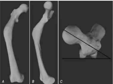
Figure 1 shows an example simulating angular and rotational deformity of the femur in a plastic bone, which can be corrected by means of single-cut oste-otomy (Figure 2).
Sangeorzan et al(5) determined the correct obliquity
AbStrAct
The direction of the obliquity of the cut for performing single-cut osteotomy to correct combined angular and rotational deformities is difficult to determine. The ap-propriate obliquity, i.e. whether clockwise or anticlo-ckwise in relation to the perpendicular to the bone axis, is usually determined through trials using plastic bone models to imitate the deformity, or on bananas, on which diffe-rent simulations can be made. This is very confusing and
difficult. In this study, we propose a table, with entries for angular and rotational deformities and the affected side. The correct obliquity of the cut in relation to the perpen-dicular to the diaphyseal axis is directly indicated in the table. A step-by-step review of the preoperative planning of the single-cut osteotomy is also presented, with emphasis on the proposed contribution.
Keywords - Osteotomy; Bone and Bone. Bone Deformity.
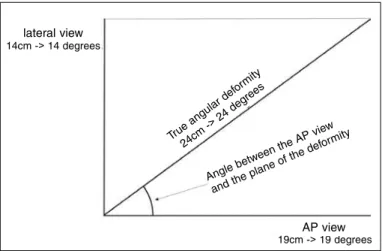
of the cut that would be required to enable simulta-neous exact correction of the angular and rotational deformities, through simple alignment of the bone and sliding the osteotomy surfaces across each other. Through developing a mathematical formula and inputting different magnitudes of angular deformity and rotational deformity to be corrected, these authors constructed a diagram (Figure 3).
Consequently, the closer to transversal to the diaphy-seal axis that the cut is made, the greater the rotational correction and the smaller the angular correction ob-tained will be, through sliding the cut surfaces across each other. The greater the inclination of the cut in re-lation to the plane transversal to the diaphyseal axis is, the greater the angular correction and the smaller the rotational correction will be. Therefore, there should be an ideal obliquity for the osteotomy cut, which would make it possible to simultaneously correct the two errors existing in a given patient, through simply Figure 1- plastic bone imitating an angular deformity (A: varus; and b: antecurvatum) and a rotational deformity (c: increased anteversion and internal rotational error) in a right femur.
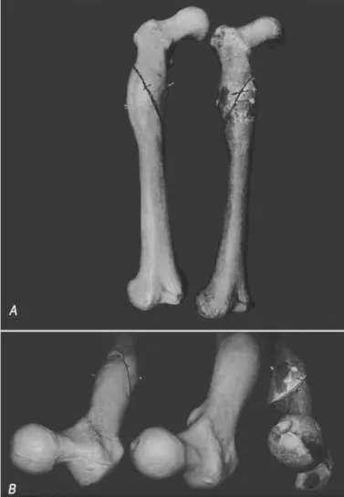
Figure 2 – the same model as in figure 1, after correction using a single cut and sliding the cut surfaces across each other, with a cut performed using the correct obliquity. It can be seen that both deformities (angular and rotational) were corrected at the same time.
Figure 3 – Sangeorzan’s diagram (from Sangeorzan et al.5). The true angular deformity (x axis) and the rotational deformity to be corrected (y axis) are plotted, thus obtaining curves corres-ponding to different cut obliquities. the curve that comes closest to the patient’s coordinates indicates the cut obliquity to be used.
sliding the osteotomy surfaces across each other and thereby rectifying the bone deformity.
However, the diagram described by Sangeorzan does not include one important parameter: the di-rection of the obliquity of the cut, i.e. whether it is clockwise or anticlockwise in relation to the perpen-dicular to the diaphyseal axis, at the osteotomy site. If a wrong decision were made in this respect, thus inverting the obliquity, this would imply not only fai-lure to correct the rotational error, but also in reality increasing it, even though it would still be possible to correct the angular deformity (Figure 4).
In the example shown in Figure 4, two models with the same deformity were cut using the same degree of
obliquity, as indicated in Sangeorzan’s diagram(5), but
in opposite directions. In both models, angular correc-tion was possible. In the model in which the direccorrec-tion of the obliquity was right, the excessive anteversion was also corrected. On the other hand, in the model in which the obliquity was erroneously inverted, the anteversion was inadvertently increased.
The method generally recommended for determi-ning the direction of the obliquity is to use bananas as
models for the patient’s deformed bone. The natural
angular deformity of the banana is positioned such
that it is similar to the patient’s deformity, paying at -tention to the cardinal points (proximal/distal; medial/
lateral)(6). A process of making clockwise and
anticlo-ckwise oblique cuts in relation to the long axis of the torsional deformity
+/-t (degrees)
banana is then begun, with careful observation of the direction in which the distal segment rotates when the curvature of the banana is corrected by sliding the cut surfaces across each other. The correct inclination is selected, i.e. the one that produces the correct direction
of rotation needed to correct the patient’s erroneous
rotation (internal or external, according to the case).
More recently, Meyer et al(7) developed a very
complex instrument for determining the inclination of the cut. According to these authors, the reason why they developed their apparatus was that the “problem with calculated angles is to understand the orientation
of the osteotomy plane, as the correct plane may be angulated either proximally or distally to the transverse plane and be oriented either clockwise or counterclockwise. This may be confusing and may promote errors since there is no uniform or standardized way for the look-up tables to address the sense of rotation or angulation”. Even with their geometrical instrument, it seems to be difficult to determine the direction of the cut, because the instrument needs to be sterilized and cannot be positioned close to the bone because of the soft tissues.
Christian(8) proposed that a three-dimensional
mo-del of the deformity should be created to simulate the two different possibilities, and to test the correction achieved through the calculated angles. This method implies that plastic bone models need to be available: these are previously sectioned at the level of the de-formity, and a deformity similar to that of the patient is created in the process of joining the segments to-gether with epoxy resin. An additional limiting factor is the difficulty in understanding the deformity pre-sented by the patient in question and in reproducing this in the model.
The issue that we wanted to address in the present study was therefore: how can the correct direction for the obliquity of the single cut be determined? In other words, whether it should be made clockwise or anticlockwise in relation to the diaphyseal axis.
We also present a step-by-step guide to planning and carrying out this difficult osteotomy procedure, because we judge that the literature is insufficient in this respect. We believe that this systematized appro-ach will greatly facilitate performing the osteotomy.
Preoperative planning for single-cut osteotomy The preoperative planning for performing single-cut osteotomy includes six important steps.
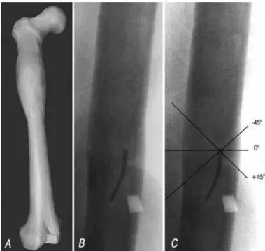
The first step is to determine the true angular de-formity and the plane of the dede-formity. For this, the rectangle rule is used(4) .
The radiographic views generally used for asses-sing the deforming (i.e. anteroposterior (AP) and la-teral views) correspond to projections in orthogonal planes of the true deformity. Thus, what is seen on radiographs is not the true deformity but, rather, pro-jections of the deformity in orthogonal planes.
The sides of a rectangle can be regarded as pro-Figure 4 – Two plastic models with the same deformity as in the
jections of the diagonal onto orthogonal planes. By analogy, if a rectangle were constructed with sides of lengths proportional to the angles measured on the AP and lateral radiographs, the length of the dia-gonal would be proportional to the true deformity. Hence, a rectangle is constructed in which the sides are represented in units of length (cm, mm or inches), proportionally to the angles measured (in degrees) on the AP and lateral radiographic views. The length of the diagonal of the rectangle thus constructed is then measured, and this measurement of length is trans-formed into degrees, using the same conversion rule used for the sides of the rectangle. In this manner, the magnitude in degrees of the true angular deformity is obtained. In addition, the angles that the diagonal forms with the sides of rectangle thus constructed are measured: these are the angles that the plane of the deformity makes with the AP and lateral planes (Figure 5). These reference points are of great impor-tance for correctly locating the plane of the deformity during the operation, given that the osteotomy has to be made along this plane.
The second step is to estimate the rotational error that is to be corrected. This is usually done from tomo-graphic slices through the proximal and distal regions of the bone. The measurements thus obtained are com-pared with the opposite side, or with population-based angle data when the opposite side is also abnormal.
The third step is to determine the angle of obliquity
of the osteotomy cut. For this, Sangeorzan’s diagram
is used(5) (Figure 1). The rotation to be corrected and
the true angular deformity are plotted on the diagram and the curve that comes closest to the intersection of the coordinates is ascertained. The curve thus se-lected indicates the obliquity of the cut in relation to the perpendicular to the diaphyseal axis, in the plane and at the apex of the deformity.
The fourth step is to determine the plane and apex of the deformity during the operation.
The plane of the deformity can be determined in two ways during the operation:
1) From the rectangle (Figure 5), as mentioned earlier, using the angles that the diagonal forms with each “plane” (AP and lateral). The plane of the deformity is then established during the operation, based on the angles measured in the rectangle;
2) It can be done much more easily, when possible, by
observing the deformity on an image intensifier screen when the limb or the radius is rotated. There will be one position within this rotation, at which the deformity disappears from the screen. At this position, the radius is exactly in the plane of the deformity (Figure 6A).
The apex is the vertex of the deformity (the most salient point of the convexity) in the plane of the de-formity. It is the center of the dede-formity. The osteo-tomy should be performed in the plane and at the apex of the deformity.
Also in the fourth step, a Kirschner wire is inserted at the apex and in the plane of the deformity (Figures 6 A and B). It is used as a reference point for tracing out the osteotomy (Figure 6C) and also serves as a support for the saw blade at the time of performing the osteotomy.
The fifth step is to establish the direction of the obliquity of the cut, i.e. whether it is clockwise or anticlockwise in relation to the perpendicular to the diaphyseal axis, at the apex of the deformity. This is the point at which the table that we have devised comes into action.
Figure 5 – Example of estimation of the true angular deformity and the position of the plane of the deformity, using the rectangle rule. In this example, the angles measured on radiographs were 19° in Ap view and 14° in lateral view. A rectangle was construc-ted such that one side represenconstruc-ted the Ap plane and the other, the lateral plane. The angles measured on radiographs were transformed into units of length (in this example, one degree cor-responded to 1 cm). the diagonal was measured with a ruler (in this case, 24 cm) and this measurement was transformed into degrees, using the same conversion rule (24 cm corresponded to 24°). this angle was the true angular deformity, which when projected in the Ap plane was 19° and in the lateral plane, 14°. By measuring the angles formed between the diagonal and the AL and lateral planes (43° with the Ap plane and 47° with the lateral plane), the position of the plane of the deformity relative to the AP and lateral planes was obtained.
14cm -> 14 degrees
True ang
ular d eformi
ty
24cm -> 24
degre es
Angle b
etween
the AP view
and the plane
of the deformi
ty
Table 1 was developed to answer the question of whether the osteotomy should be performed with its obliquity inclined in the clockwise or anticlockwise direction. This table was developed and validated by trial and error, using banana models, plastic models of bone deformities and cases operated previously.
Through inputting the side affected and the rota-tional error to be corrected, Table 1 directly indicates the direction of the inclination that the path of the osteotomy should have, starting from the zero
posi-tion (perpendicular to the axis of the bone, seen at the apex and in the plane of the deformity; Figure 6B). If the clockwise direction is indicated, the path should be inclined in the clockwise direction from the zero position.
The approach taken towards the deformity is gene-rally through its convexity. Exceptionally, when the apex is in a difficult-to-access position, the approach taken may be through the concavity of the deformity. In the latter situation, the K wire is inserted in the plane of the deformity and at the center of the defor-mity, but through the concavity and seeking the apex, which is at the opposite side. The difference in this case is that the direction of the inclination (clockwise or anticlockwise) should evidently be the opposite of what is indicated in our table.
The sixth step is to trace out the path of the osteo-tomy during the operation. The perpendicular to the diaphyseal axis in the plane of the deformity and at the apex of the deformity is the zero reference point for determining the obliquity of the cut indicated in
Sangeorzan’s diagram(5).
In the plane of the deformity (i.e. when the de-formity disappears from the screen), a line is traced out on the bone, going along the K wire and incli-ned in relation to the perpendicular to the diaphyseal
axis, at the angle indicated by Sangeorzan’s diagram.
Clockwise inclinations will be paths inclined in the clockwise direction in relation to the zero position (Figure 6C).
The osteotomy is then performed along the path traced out, using the K wire as the support for the saw blade.
The bone is aligned through alignment maneuvers and by sliding the cut surfaces across each other. Fixa-tion is then performed using the method that is most appropriate for the case (intramedullary nail or plate).
diScUSSiON
The novel feature of the present study is the proposal for a table to determine the obliquity of the single cut.
The decision regarding the angle of obliquity de-rived from estimates in accordance with the proposal
of Sangeorzan(5) is straightforward. The difficulty is
in deciding whether the obliquity should be clockwise or anticlockwise, in relation to the perpendicular to Figure 6 – By rotating the limb or the radius and observing this
on the image intensifier screen, it was seen that there was one position at which the angular deformity was rectified (A and B). this occurred when the X-ray beam was exactly in the plane of the deformity. In (b), a kirschner wire was inserted at the apex and in the plane of the deformity. In (c), the possible paths for the osteotomy are demonstrated, for an inclination of 45°, obtained from Sangeorzan’s diagram5,6. the zero position is perpendicular to the diaphyseal axis of the bone, viewed in the plane of the deformity.
table 1- Table indicating the direction in which the cut should be inclined from the zero position (perpendicular to the longitudinal axis of the bone, viewed in the plane of the deformity). clockwise means an inclination of the cut in the clockwise direction, from the zero position.
Side torsional error to be corrected inclination of the cutdirection of the
Right Internal Clockwise
Right External Anticlockwise
Left Internal Anticlockwise
the diaphyseal axis, as seen at the apex and in the plane of the deformity. A wrong decision in this res-pect implies increasing the rotational error, instead of correcting it.
Meyer et al7 developed a complex geometrical
tool with this purpose. However, they admitted that the “problem with calculated angles is to understand the orientation of the osteotomy plane, as the correct plane may be angulated either proximally or distally to the transverse plane and be oriented either clo-ckwise or countercloclo-ckwise. This may be confusing and may promote errors since there is no uniform or standardized way for the look-up tables to address the sense of rotation or angulation”. The difficulty in acquiring the tool, the difficulty in understanding and using it, the sterilization process that is required and the difficulty in bringing it close to the bone at the time of the surgery are points of concern.
The ideal solution would be to have plastic mo-dels available for reproducing the deformity
(proto-types constructed according to each patient’s defor -mity). Such models would be used to test different osteotomy procedures based on angles obtained from
Sangeorzan’s diagram, with the aim of checking the
correct direction for the obliquity. However, using these models is extremely costly and is inaccessible for the vast majority of surgeons.
The exercise using bananas requires great expe-rience and a high level of spatial intelligence on the part of the surgeon, and has the potential to cause great confusion.
These are the reasons why we are proposing a table from which the information can be obtained easily and securely.
The table presented was validated by testing it on plastic models of deformed bone, on bananas and on cases operated previously, and also on cases operated more recently.
The possibility that the approach taken towards the deformity might have to be through the concavity, and consequent consideration of the side to be operated and its repercussions with regard to determining the direction of the obliquity of the cut, were not previously dealt with in the literature.
We believe that the table described here (Table 1) provides a simple and secure means of determining the small detail of whether the obliquity should be clockwise or anticlockwise in relation to the perpen-dicular to the diaphyseal axis, as seen at the apex and in the plane of the deformity. Nevertheless, this detail is of crucial importance for carrying out sin-gle-cut osteotomy to correct combined angular and rotational deformities.
cONclUSiON
We also believe that the step-by-step description of single-cut osteotomy, as described here, which has not been available in the literature, will simplify the planning and execution of this difficult procedure for those who wish to make use of this elegant and effi-cient manner of correcting mixed angular and rota-tional deformities.
rEFErENcES
1. D’Aubigné RM, Descamps L. L’osteotomie plane oblique dans la correction des deformations des members. Bull Mem Arch Chirurg. 1961;8:271-6.
2. Johnson EE. Multiplane correctional osteotomy of the tibia for diaphyseal ma-lunion. Clin. Orthop Relat Res. 1987;(215):223-32.
3. Kruse RW, Bowen JR, Heihoff S. Oblique tibial osteotomy in the correction of tibial deformity in children. J Pediatr Orthop. 1989;9(4):476-82.
4. Payley D. Angulation rotation deformities. In: Principles of deformity correction. Berlin, Heidelberg: Springer Verlag; 2002. p. 252-66.
5. Sangeorzan BJ, Sangeorzan BP, Hansen ST, Judd RP. Mathematically directed single-
cut osteotomy for correction of tibial malunion. J Orthop Trauma. 1989;3(4):267-75.
6. Paccola CAJ. Como planejar osteotomias corretivas com desvios angular e rotacional com um único corte de serra. Rev Bras Ortop. 1997;32(6):413-7.
7. Meyer DC, Siebenrock KA, Schiele B, Gerber C. A new methodology for the planning of single-cut corrective osteotomies of mal-aligned long bones. Clin Biomech (Bristol, Avon). 2005;20(2):223-7.