ORIGINAL ARTICLE
1 – Orthopedist, Hospital Felício Rocho, Belo Horizonte, MG, Brazil.
2 – Mechanical Engineer and MSc in Mechanical Engineering with emphasis on Biomechanics, SCiTec, Florianópolis, SC, Brazil.
3 – Mechanical Engineer and PhD in Mechanical Engineering with emphasis on Biomechanics, Department of Metal Mechanics, Federal Institute of Education, Science and Technology of Santa Catarina (IF-SC), Florianópolis, SC, Brazil.
4 – Orthopedist and MSc in Medical Sciences, University Hospital of the Federal University of Santa Catarina (UFSC), Florianópolis, SC, Brazil.
Work performed in the Department of Metal Mechanics, Federal Institute of Education, Science and Technology of Santa Catarina (IF-SC), Florianópolis, SC, Brazil.
Correspondence: Rua Patagônia 55/1101, 30320-080 Belo Horizonte, MG. E-mail: [email protected]
Work received for publication: September 21, 2011; accepted for publication: February 9, 2012.
RELATIONSHIP BETWEEN RIGIDITY OF EXTERNAL FIXATOR
AND NUMBER OF PINS: COMPUTER ANALYSIS
USING FINITE ELEMENTS
Marcelo Back Sternick1, Darlan Dallacosta2, Daniela Águida Bento3, Marcelo Lemos do Reis4
ABSTRACT
Objective:To analyze the rigidity of a platform-type
ex-ternal fixator assembly, according to different numbers of pins on each clamp. Methods: Computer simulation on a large-sized Cromus dynamic external fixator (Bau-mer SA) was performed using a finite element method, in accordance with the standard ASTM F1541. The models were generated with approximately 450,000 quadratic te-trahedral elements. Assemblies with two, three and four Schanz pins of 5.5 mm in diameter in each clamp were compared. Every model was subjected to a maximum force of 200 N, divided into 10 sub-steps. For the components, the behavior of the material was assumed to be linear,
16 artigo 594
INTRODUCTION
The use of external fixators goes back to the times of Hippocrates. Over the years, a variety of modifica-tions have been made, both in relation to the materials used and in the design of their components, so that their stability could be increased and the complica-tions inherent to the apparatus could be minimized(1).
After the Second World War, great advances were made until reaching the modern external fixator in the 1970s. Biomechanical laboratory tests started to be done, until the study by Huiskes and Chao, who were the first to standardize these analyses for different types of external fixator(2).
The first study using finite elements involving ex-ternal fixators was conducted in 1979. Since then,
this technique has been widely used to simulate the various situations relating to setting up an external fixator, by means of computational models.
In the present study, a computational simulation of an external fixator system was conducted in order to supply reference values that could subsequently be validated ex-perimentally. The finite elements method was used so as to establish a relationship between the stiffness of the as-sembly and the number of Schanz pins used in the system.
MATERIALS AND METHODS
A computational simulation was conducted on the large-size Cromus dynamic external fixator (Baumer S.A.). The models were analyzed taking into con-sideration the assembly requirements of the ASTM
The authors declare that there was no conflict of interest in conducting this work
This article is available online in Portuguese and English at the websites: www.rbo.org.br and www.scielo.br/rbort
elastic, isotropic and homogeneous. For each model, the rigidity of the assembly and the Von Mises stress distri-bution were evaluated. Results: The rigidity of the system was 307.6 N/mm for two pins, 369.0 N/mm for three and 437.9 N/mm for four. Conclusion: The results showed that four Schanz pins in each clamp promoted rigidity that was 19% greater than in the configuration with three pins and 42% greater than with two pins. Higher tension occurred in configurations with fewer pins. In the models analyzed, the maximum tension occurred on the surface of the pin, close to the fixation area.
(American Society for Testing and Materials) tech-nical standard F1541 – Standard Specification and Test Methods for External Skeletal Fixation Devices (Figure 1 and Table 1).
The distance Po, located close to the focus of the fracture could not be met due to the geometrical cha-racteristics of the fixator. The models were analyzed using the NX Nastran commercial package, and were generated with approximately 450,000 quadratic te-trahedral elements. The mesh can be seen in Figure 2. During the analyses, three assembly configurations were evaluated:
With two bone pins in each of the platforms (upper and lower), in the positions AA-DD;
With three bone pins in each of the platforms (upper and lower), in the positions AA-CC-DD;
Figure 1 – Assembly characteristics in accordance with ASTM F1541.
Table 1 – Assembly parameters.
OS 90 mm
Fo 50 mm
G 20 mm
D 30 mm
Po 20 mm
Go 167 mm
Figure 2 – Finite-element mesh.
Frontal view
Top view
With four bone pins in each of the platforms (upper and lower), in the positions AA-BB-CC-DD.
Schanz pins of diameter 5.5 mm were used. The pin positions can be seen in Figure 3.
Each fixator model was subjected to a maximum force of 200 N, which was equivalent to the maxi-mum axial force supported by these devices during the patient’s recovery phase(3).
The force was applied perpendicularly to the upper face of bone substitute 1; while this was being done, bone substitute 2 remained embedded on the lower face.
For all the components of the system, it was assu-med that the behavior of the material was homogenous, linear, elastic and isotropic, defined using the modulus of elasticity E and Poisson’s coefficient υ (Table 2).
Figure 3 – Assembly configurations.
Position D Position C
Position B Position A
Position A Position B
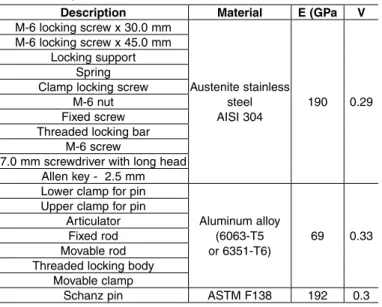
Table 2 – Properties of the materials.
Description Material E (GPa V
M-6 locking screw x 30.0 mm
Austenite stainless
steel
AISI 304 190 0.29 M-6 locking screw x 45.0 mm
Locking support Spring Clamp locking screw
M-6 nut Fixed screw Threaded locking bar
M-6 screw
7.0 mm screwdriver with long head Allen key - 2.5 mm Lower clamp for pin
Aluminum alloy (6063-T5
or 6351-T6) 69 0.33 Upper clamp for pin
Articulator Fixed rod Movable rod Threaded locking body
Movable clamp
Schanz pin ASTM F138 192 0.3
RESULTS
For each of the models analyzed, the rigidity re-lating to the system was evaluated. The results are presented in Table 3.
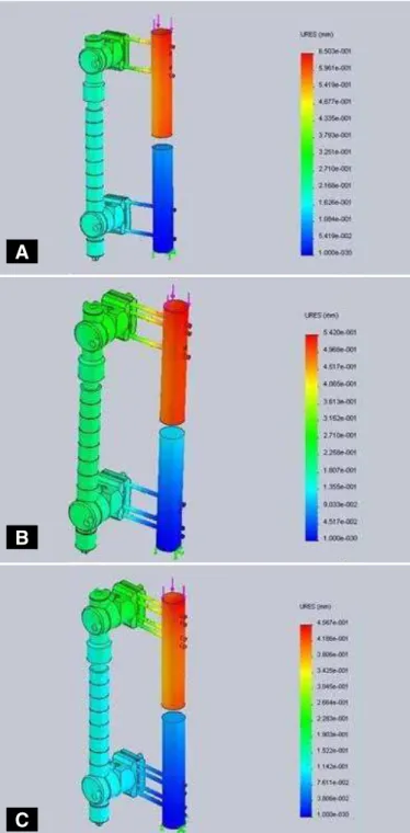
Figure 4 (A, B and C) presents the von Mises maxi-mum tension results for the three assembly proposals evaluated. For the force of 200 N, the field of resultant displacements for the assemblies can be seen (Figure 5 – A, B and C). On the deformed image, the scale was artificially increased so as to facilitate viewing.
Table 3 – Stiffness of the system.
Configuration Stiffness (N/mm)
With 2 bone pins 307.6 With 3 bone pins 369 With 4 bone pins 437.9
Figure 4 – Von Mises tension: (A) for configuration with four pins; (B) for configuration with three pins; (C) for configuration with four pins.
DISCUSSION
Over recent decades, there have been enormous advances in external fixation. Several types of appa-ratus have been introduced, always seeking the best in terms of components and design. Biomechanical studies are increasingly necessary in order to attest to the stability of the system. In 1986, Huiskes and Chao were the first to standardize these studies by issuing guidelines for biomechanical evaluations(2).
Today, the technical standard most used for eva-luating external fixators and their components is the ASTM standard, and the main reference is ASTM F 1541 – 02 (2011) – Standard Specification and Test Methods for External Skeletal Fixation Devices, whi-ch was used in the present study(4).
The first study using finite elements in relation to external fixation was published in 1979, seven ye-ars after the first study using this method in ortho-pedics(5). Since then, several other studies have been
conducted(6-11). Studies using this technique have also
been published in the Brazilian literature, but not with simulation of an external fixator(12-14).
The commercial finite-element packages available are very versatile tools for evaluating the influence of
A
B
assembly parameters in relation to the axial stiffness of a particular external fixator, because of the ease of modifying the geometrical characteristics of the assembly and outline conditions of the model. The advantages of computational finite-element models are the possibilities of modifying various parameters easily and systematically(7), evaluating the stiffness without the need for experimental tests(11) and
dis-pensing with studies on animals, which are becoming
Figure 5 – Resultant displacement: (A) for configuration with four pins; (B) for configuration with three pins; (C) for configuration with four pins.
increasingly difficult to undertake nowadays.
Stability is the main characteristic of an external fixator. However, the stiffness of the system needs to allow micromovements, which are necessary for the bone consolidation process(11). It is known from
stu-dies on animals that movements between fragments should remain within the range of 0.2 to 1.0 mm(15).
The stability of a system depends both on the appa-ratus and its components (pins, bars and clamps) and on the patient (type of fractures, presence of systemic diseases, bone quality, acquired infection at the pin sites, etc), as well as on the technique used for place-ment and length of use. Among these, the number of pins used on the bone fragments is one of the most important parameters and if used improperly, this may lead to significant changes in fixator use(8).
For this reason, comparative evaluations are con-ducted on the fixator with different quantities of pins in each clamp, knowing from the outset that the grea-ter the quantity of pins is, the greagrea-ter the stability will be. This therefore enables quantitative assessment of the stability of the system, insofar as it depends on this variable. In the present study, a platform-type dynamic external fixator was used, composed of a bar and two multiplanar clamps, which made it possible to place up to four pins in each segment.
The distance Po could not be met because of the construction characteristics of the Cromus fixator. This distance is taken into account only for fixator models that possess smooth bars and allow pin dis-tribution to any point along its length. Increasing the distance Po tends to increase the flexibility of the system, but there is no variation in the flexor moment. The system was tested in accordance with the indications for its use, which tends to repro-duce the behavior of the fixator more faithfully. The technical standard serves as a guiding docu-ment and thus, it allows changes in configuration to be made, provided that these are properly related and considered. It should be emphasized that the remaining parameters were maintained as establi-shed by ASTM F1541.
The von Mises tension criterion is based on the Mises-Hencky theory, also known as the theory of maximum distortion energy. The theory says that a ductile material starts to fail at a site at which the equivalent von Mises tension reaches the yield point of the material.
A
B
The aim of the present study was to analyze the sti-ffness of the assembly and not to determine the likely failure sites. In assessing the stiffness, the system was subjected to a state of tension that would not result in plastic deformation of components. This was proved, because all the results relating to the equivalent von Mises tension were below the yield tension of the materials used in manufacturing the components.
The mechanical properties were obtained from the respective technical standards for the raw materials. Thus, variations below the minimum limits establi-shed by the standards were disregarded. Issues rela-ting to surface finishing are irrelevant in this type of analysis, since they are controlled during the manu-facturing process of the components. The real model has characteristics that from a structural point of view are identical to the numerical model.
The model was not subjected to tensions greater than the yield point of the materials and therefore did not start to present plastic deformation. The stiffness of the system is determined within the elastic regime. In design terms, the components are designed to func-tion only within the elastic regime, i.e. occurrences of plastic deformation tend to provoke functional failure.
CONCLUSION
The results demonstrated that four Schanz pins per clamp promoted stiffness that was 19% greater than in the configuration with three pins and 42% greater than in the configuration with two pins.
The greatest von Mises tension occurred with the configuration with the smallest number of pins, because in this case, the reactions must be supported by a smal-ler number of elements. For all the models analyzed, the maximum tension occurred on the surface of the Schanz pins, close to the fixation, since this was the site with the largest flexor moment and least section. The main parameters that influenced axial stiffness and tension distribution in the assembly were the number of pins and the distance Fo. For this condition, the smaller the distance Fo was, the greater the stiffness and the smal-ler the flexor moment would be, which would tend to diminish the von Mises tensions in the assembly.
ACKNOWLEDGEMENTS
Our thanks to Baumer S.A., for making available the 3D geometrical fixator models used and for pro-viding technical support for accomplishing this work.
REFERENCES
1. Sternick MB. A história da fixação externa. In: Andrade MAP, Silva WN, edi-tores. Clínica ortopédica da SBOT. Avanços em alongamento e reconstrução óssea. Rio de Janeiro: Guanabara Koogan; 2010. p. 98-103.
2. Huiskes R, Chao EY. Guidelines for external fixation frame rigidity and stresses. J Orthop Res. 1986;4(1):68-75.
3. Vijayakumar V, Marks L, Bremmer-Smith A, Hardy J, Gardner T. Load transmission through a healing tibial fracture. Clin Biomech (Bristol, Avon). 2006;21(1):49-53. 4. ASTM Comitee F04 on Medical and Surgical Materials and Devices. Designa-tion F 1541-02. Standard SpecificaDesigna-tion and Test Methods for External Skeletal Fixation Devices, 2002.
5. Huiskes R, Chao EY. A survey of finite element analysis in orthopedic biome-chanics: the first decade. J Biomech. 1983;16(6):385-409.
6. Huiskes R, Chao EY, Crippen TE. Parametric analyses of pin-bone stresses in external fracture fixation devices. J Orthop Res. 1985;3(3):341-9.
7. Drijber FL, Finlay JB, Dempsey AJ. Evaluation of linear finite-element analysis models’ assumptions for external fixation devices. J Biomech. 1992;25(8):849-55. 8. Juan JA, Prat J, Vera P, Hoyos JV, Sánchez-Lacuesta J, Peris JL, et al.
Biome-chanical consequences of callus development in Hoffmann, Wagner, Orthofix and Ilizarov external fixators. J Biomech. 1992;25(9):995-1006.
9. Koo TK, Chao EY, Mak AF. Fixation stiffness of Dynafix unilateral external fixator
in neutral and non-neutral configurations. Biomed Mater Eng. 2005;15(6):433-44. 10. Radke H, Aron DN, Applewhite A, Zhang G. Biomechanical analysis of unila-teral external skeletal fixators combined with IM-Pin and without IM-Pin using finite-element method. Vet Surg. 2006;35(1):15-23.
11. Watson M, Mathias KJ, Maffulli N, Hukins DW, Shepherd DE. Finite element modelling of the Ilizarov external fixation system. Proc Inst Mech Eng H. 2007;221(8):863-71. 12. Queiroz RD, Lima RG, Del Pino GG, Mestriner LA, Takata ET. Análise do
desgaste do polietileno do componente acetabular da prótese total do quadril, utilizando o método de elementos finitos de simulação computadorizada. Rev Bras Ortop. 2001;36(5):149-54.
13. Soni JF, Santili C, Lancelotti CLP, Hecke MB, Almeida FR, Karam LZ. Análise comparativa em modelo computadorizado bidimensional em simulação do emprego de hastes flexíveis de aço e titânio, na fratura do fêmur na criança, utilizando o método de elementos finitos. Rev Bras Ortop. 2008;43(5):183-92. 14. Gabrieli APT, Lemos RR, Henrich CH. Ferramenta computacional para estudo da