Model for Predicting Damage Evolution in
Heterogeneous Viscoelastic Asphaltic Mixtures
Article in Transportation Research Record Journal of the Transportation Research Board · January 2004
DOI: 10.3141/1891-16
CITATIONS
31
READS
115
4 authors, including:
Some of the authors of this publication are also working on these related projects:
Recycling, skid resistance, noise reduction, pavement design, railway ballastView project
Mechanical characterization of asphalt mixturesView project J. B. Soares
Universidade Federal do Ceará
149PUBLICATIONS 497CITATIONS
SEE PROFILE
David Allen
Texas A&M University
177PUBLICATIONS 2,853CITATIONS
SEE PROFILE
All content following this page was uploaded by J. B. Soares on 28 January 2014.
Asphaltic Mixtures
Submission date: 11/15/2003 Word count: 7,269
Flávio Vasconcelos de Souza Universidade Federal do Ceará Campus do Pici, s/n – Bloco 703
Zip code: 60.455-760 - Fortaleza, CE – Brazil (55)(85) 288.9572 – R 242
Jorge Barbosa Soares Universidade Federal do Ceará Campus do Pici, s/n – Bloco 703
Zip code: 60.455-760 - Fortaleza, CE – Brazil (55)(85) 288.9572 – R 244
David H. Allen
University of Nebraska – Lincoln College of Engineering
Zip code: 68588 - Lincoln, Nebraska (402) 472-3181
Francisco Evangelista Jr. Universidade Federal do Ceará Campus do Pici, s/n – Bloco 703
Zip code: 60.455-760 - Fortaleza, CE – Brazil (55)(85) 288.9572 – R 242
ABSTRACT
Cracking in the asphaltic layer of pavements has been shown to be a major source of distress in roadways. Previous studies in asphaltic mixture cracking have typically not considered the material heterogeneity. This paper presents the sequel of a study in which the binder and the aggregates were treated as distinct materials. In this paper, besides the consideration of the viscoelastic behavior of the bulk asphalt binder, a micromechanical viscoelastic cohesive zone model that introduces ductility at the crack tip has also been considered. The simulations performed are verified and calibrated from simple and conventional laboratory tests. The study investigates crack evolution under monotonic loading, even though the method outlined can be further developed for the investigation of asphalt mixture fatigue.
1. INTRODUCTION
Cracking in the asphaltic layer of pavements has been considered to be a major source of distress in roadways. Many researches have studied progressive fracture in asphaltic mixtures mainly through experimental investigations (1,2). Some authors have used the Theory of Fracture Mechanics (TFM) as the basis for predicting crack growth in asphaltic mixtures, considering the material as homogeneous (3,4,5,6). The focus has typically been on the macro-scale with no consideration given to the mixture heterogeneity (7,8,9,10,11). Recently, the effect of heterogeneity has been studied in an attempt to separate the effect of each constituent on the mixture damage (12,13,14,15). Despite the improvement in the way the cracking problem in mixtures has been undertaken, the viscoelastic nature of the asphaltic material has not been considered (13,14,15,16) even though it is well recognized in the literature (9,10,11,17,18,19,20). Recent works by Kim and associates have shown the importance of considering the viscoelastic behavior of asphalt mixtures in fatigue and crack modeling (9,10,11,18,21,22). It is shown that the use of the theory of viscoelasticity produces more accurate results than an elastic approach. The work by Souza and Soares (23) shows a comparison of the pavement response when considering the viscoelastic behavior of the asphalt surface layer with respect to the response of an assumed elastic surface layer.
As the bulk material behavior itself, fracture in viscoelastic media is also time and rate dependent (24,25,26,27,28). Basically, two approaches can be used in damage analysis of viscoelastic media: (i) the continuum damage mechanics approach and (ii) the micromechanics approach. Schapery and co-workers (18,29,30,31,32) have given the direction for crack and damage modeling in viscoelastic media through the use of the continuum damage mechanics. Recent research efforts by Allen and co-workers (27,28,33,34,35) have evolved to a new micromechanical model capable of predicting crack and damage evolution in viscoelastic materials, which has been incrementalized and included into a finite element code (35).
The present study is a sequel to the work by Soares et al. (14) which considered an elastic approach for modeling cracking growth in heterogeneous asphaltic mixtures submitted to the Indirect Tension (IDT) test conditions utilizing the Finite Element Method (FEM). The goal of the present paper is to predict crack and damage evolution in asphaltic concrete (AC) mixtures considering the material heterogeneity, the viscoelastic behavior of the bulk asphalt binder and the time and rate dependence of damage evolution and crack growth by means of a micromechanical viscoelastic Cohesive Zone Model. The numerical results are then compared to experimental results obtained from the IDT test wherein monotonically increasing displacements are applied to the specimen.
Even though only monotonic loading has been considered and applied to the IDT test herein, this approach is also capable of modeling fatigue behavior in asphaltic materials (36) since history dependence has been incorporated into the critical energy release rate through the use of a viscoelastic constitutive model for the traction-displacement relationship along the crack faces.
2. BACKGROUND
Mechanistic pavement design methods can prevent cracking by limiting tensile stresses at the bottom of the surface layer with a design criterion typically determined from laboratory experiments (38). Tensile strength and fatigue tests are commonly used to develop such criteria. However, pavements develop cracks in virtually all load bearing applications. A potentially more fruitful approach to pavement design would involve a mechanistic model that can predict the evolution of damage (void formation, microcracking) as a function of the input loads, geometry, and material properties.
The approach taken herein treats asphaltic mixtures as a three phase material composed of a (i) viscoelastic asphaltic cement, (ii) elastic aggregates, and (iii) a slowly degrading viscoelastic zone that exists not only between the aggregate and the asphalt binder, but also within the asphalt binder that undergo load history induced fracture wherever there is sufficiently available energy for that. Details of this approach are described in Section 2.2.
2.1. Crack Modeling in Asphaltic Mixtures
The approaches most commonly used in fracture and damage analysis of viscoelastic media are the continuum damage mechanics approach and the micromechanics approach. The continuum damage mechanics is based on the so called internal state variables, which quantifies the damage within the assumed homogenous material and whose evolution is described by a phenomenological or semi-phenomenological model derived from laboratory or field observations. In this case, no internal boundaries are predicted in the model, but the internal variables account accurately for the energy dissipation due to crack propagation. A primary advantage of this approach is the significant saving in computational effort. The main studies in asphaltic mixtures with such an approach have been reported by Kim and associates using Schapery’s theories (9,11,18,21,22).
In the micromechanics approach, however, the damage produced by evolving internal boundaries can be actually accounted for by means of some variation of fracture mechanics, such as cohesive zone models. An important aspect of the micromechanics approach is the selection of the Representative Volume Element (RVE). Recent research efforts by Allen and co-workers (27,28,33,34,35) have developed a micromechanical model capable of predicting crack and damage evolution in viscoelastic materials under both monotonic and cyclic loading, as outlined in the next section. In the current study, only monotonically increasing displacements are considered. However, research efforts in fatigue damage modeling in asphaltic mixtures are currently under development in Brazil. The main constraint for modeling fatigue damage evolution has been the computational effort necessary for calculating the damage evolution at several hundreds of load cycles.
scale through homogenization techniques. Homogenization principles have been used in several applications in composite materials (41,42,43). The advantage of the micromechanics approach is that the physical details, which occur at the smaller scale, are not lost, whereas they are not included at all when using the phenomenological models of the continuum damage approach.
2.2. Micromechanical Viscoelastic Cohesive Zone Model
In the approach used herein, TFM is utilized in order to predict energy dissipation due to damage evolution and crack propagation in the viscoelastic asphaltic mixture. The classical TFM, as described by Griffith (44), assumes that there was no plastic deformation in the material, or such deformation is negligible (Linear Elastic Fracture Mechanics – LEFM). The LEFM cannot be used to describe cracking in asphaltic materials due to a viscoelastic ductile zone that develops ahead of a crack tip (28). An alternative approach to the LEFM is based on the so called Cohesive Zone Model (CZM) first developed by Dugdale (45) and Barenblatt (46) for elastic materials. The model is considered to be cohesive because it assumes the existence of cohesive tractions acting in the fracture process zone ahead of the crack tips, thus removing the stress singularity at the crack tip. An advantage of the CZM is that it allows crack growth analysis from pre-existing cracks as well as from plain surfaces. Such a model has been used for modeling a multitude of ductile materials, including asphaltic mixtures (14,47).
Another inviting feature of the CZM is that one can include history dependence into the critical energy release rate by assuming a viscoelastic traction-displacement relationship along the crack faces in order to allow fatigue modeling (48). Such a CZM was developed in (28) through the homogenization of an idealized viscoelastic damaged zone ahead the crack tip. This micromechanical viscoelastic damaged zone was represented by a Representative Volume Element (RVE) idealized as an assemble of cylindrical viscoelastic fibrils surrounded by air and homogenized to produce a damage dependent traction-displacement relationship for the viscoelastic cohesive zone, as follows:
[
]
⎢⎣⎡ ⎥⎦⎤ ∂ ∂ − + −=
∫
tt C f
i i
i t t E t
T 0 d ) ( ) ( 1 1 )
( * τ
τ λ τ σ α δ δ λ (1)
where σf is the required stress level to initiate damage; EC is the relaxation modulus of the fibrils, assumed herein to be the same as that of the surrounding bulk material; α(t) is the internal damage parameter; and λ is the Euclidean norm of the damage zone opening displacements given by:
2 1 2 * 2 * 2 * ) ( ⎥ ⎥ ⎦ ⎤ ⎢ ⎢ ⎣ ⎡ ⎟⎟ ⎠ ⎞ ⎜⎜ ⎝ ⎛ + ⎟⎟ ⎠ ⎞ ⎜⎜ ⎝ ⎛ + ⎟⎟ ⎠ ⎞ ⎜⎜ ⎝ ⎛ = s s r r n n t δ δ δ δ δ δ λ (2)
where δn, δr, and δs are the local coordinate components of the damage zone opening displacements, and *
n
δ , *
r
δ and *
s
δ are empirical material length parameters.
A t A A t N k k
∑
= − = 1 ) ( ) (α (3)
where Ak(t) is the cross-sectional area of the kth fibril and N is the number of fibrils in the RVE.
Since the experiments required to determine the viscoelastic cohesive zone parameters are difficult to perform (49), it is simpler to assume a phenomenological damage law capable of expressing the decreasing fibril volume fraction. The damage law (equations 4a-c) used herein is based on that used in (28), which explicitly reflects effects through the time-derivative of α(t) (overdot denotes a time derivative):
1 and 0 for
1 ≥ ≤
=αλ λ α
α& m &
(4a) 1 or 0 for
0 ≤ =
= λ α
α& & (4b)
) (
1
1 α u&
α ≡ (4c)
where α1 and m are material damage parameters.
However, as experimentally observed in (18) and in the current paper, the evolution of damage in asphaltic mixtures is dependent upon both strain rate and time (loading duration). Therefore, in order to include strain rate dependence into equation 4a, the parameter α1 was assumed to be a function of the applied displacement rate u& (equation 4c).
Since, in general, equation 1 cannot be analytically integrated due to the nonlinearities included by equation 4, an incrementalized form of the traction-displacement relationship in equation 1 is desired in order to incorporate the CZM into a finite element code (28). Allen and Searcy (35) have developed such an incrementalized traction-displacement relationship based on the method previously outlined in (50). The resulting viscoelastic CZM was implemented in a computer code - SADISTIC (33) - using the CZ FEM formulation described in (51). The FEM formulation of this viscoelastic CZM is of major importance since the viscoelastic crack problem in composite materials has no analytical solution (33,34,51,52,53).
In the numerical analysis of a material, the model parameters can be calibrated from laboratory tests under strain control. In other words, the parameters can be calibrated in such a way as to reproduce the force-displacement curve obtained from experiments. Such a procedure was used in (52) for modeling crack growth in Portland cement concrete in modes I and II, with the material assumed to be homogeneous and in (14) for modeling crack propagation in assumed elastic asphaltic mixtures considering material heterogeneity. Phillips et al. (53) used the same approach to model laminated composite materials.
3. METHODOLOGY
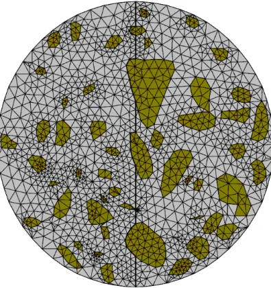
this model includes the development of a mesh generator capable of embedding CZ elements within the entire mesh. Figure 1 shows the finite element mesh used (the interface elements are in bold line).
Then, numerical simulations of the IDT test assuming plane strain conditions were carried out by applying a monotonically increasing displacement in diametral compression and the numerical results were compared to the laboratory experiments. The tests were performed at displacement rates of 0.8, 1.6 and 3.2mm/sec, so that inertial effects could be neglected, and three samples were tested for each displacement rate.
The aggregate mixture for the asphalt concrete (AC) follows Brazilian specifications (54) and has granite as the coarse aggregate. The nominal maximum aggregate size for the mixture was 12.5mm. The asphalt cement content was 7.0%, Va = 4.0% and VAM = 17.4%. The asphalt cement used is a PG 64-16 produced at the PETROBRAS refinery in Fortaleza from the Venezuelan Bachaquero crude.
It is important to note that one cannot adequately model all the aggregates in the cross section, but there exists a minimum aggregate size that can be captured which depends on the digitizing and meshing scheme. For the present study, the minimum captured aggregate size was 3.5 mm.
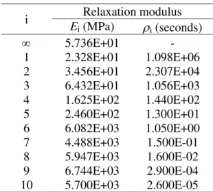
3.1. Material and Cohesive Zone Properties
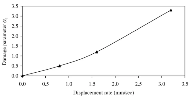
Although it is possible to consider the fines as a separate heterogeneous material by performing an analysis on a third smaller scale, the ensemble of the asphalt cement impregnated with filler and fine aggregates is considered to be a homogeneous material referred to as the binder, or mastic, herein. The aggregate elastic parameters are E = 40,500MPa and ν = 0.20, which were assumed based on (55). The binder relaxation modulus was obtained based on frequency sweep tests in shear by assuming a constant Poisson ratio of 0.30. The Prony terms of the binder relaxation modulus are given in Table 1. For the viscoelastic cohesive zone, it is assumed that its relaxation modulus is the same as that of the bulk binder. The required stress level for damage initiation, σf, was taken to be 0.50MPa for the binder-aggregate interface and 4.00MPa for the binder itself, for both tangential and normal directions. The damage parameter m for which the numerical analyses reproduce the experimental results was 0.10 and the parameter α1(u&) was 0.5, 1.2 and 3.3 for the
displacement rates of 0.8, 1.6 and 3.2mm/sec, respectively. Figure 2 presents a plot of α1 as a function of the applied displacement rates. The empirical material length parameters, *
n
δ and
*
r
δ (for two-dimensional problems, only two local coordinate components of the damage zone opening displacements have to be considered) were taken to be 10cm (equal to the diameter of the specimen).
Note that the material properties assumed may be verified by comparing the initial slopes of the experimentally and numerically obtained force-pseudo displacement curves (see Figure 5a), given that at low strain levels no significant damage has occurred, and force is linearly proportional to pseudo displacement (equation 5) (25).
∫
− ∂∂= R− t
R
d u t E E u
0 1
)
( τ
τ
τ (5)
where ER is the so-called reference modulus, herein taken to be equal to the initial modulus of
29,549MPa.
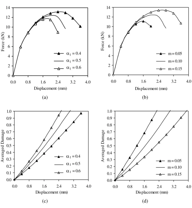
monotonically increasing displacements can be found in (28). Figure 3 shows a sensitivity analysis with respect to the damage parameters for the IDT test conditions (u& = 0.8mm/sec). It can be observed that the damage parameters have a significant influence on the model performance. As shown in Figure 3, the higher α1 and the lower m, the lower is the energy dissipation in the system.
Furthermore, due to the incrementalized form of the finite element CZM, the model accuracy is also dependent on the time increment. In the current study, convergence for 0.8, 1.6 and 3.2mm/sec was achieved with a time step of 0.50, 0.25 and 0.1sec, respectively.
4. RESULTS
Figure 4a presents the experimental force-displacement curves of the controlled strain IDT test compared to the numerical results obtained utilizing the viscoelastic approach outlined herein (displacements are measured diametrically). Figures 4b-e show the predicted crack growth within the specimen for the displacement rate of 0.8mm/sec at selected points in the force-displacement curve.
It is important to note that if one utilizes the same α1 calibrated for one displacement rate for the other displacement rates, agreement between experimental and numerical results is not achieved for these other displacement rates, indicating that, despite its dependence on the load duration, the evolution of damage in asphaltic mixtures is highly dependent on the strain rate, as pointed out in (18). For this reason, the parameterα1 was defined as a function of the applied displacement rate, as described in section 2.2.
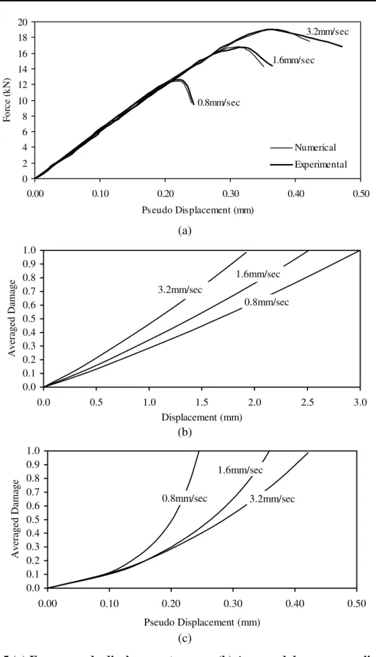
Figure 5a presents the force-pseudo displacement curves. Note that the material properties utilized herein are suitable since the initial slope of the experimental and numerical curves in Figure 5a are in agreement. Figure 5b shows the evolution of the averaged damage, which can be obtained by averaging the damage in the cohesive zone elements, with respect to the applied displacement. It can be observed that for a given displacement (strain) level, higher displacement rates induce more damage than lower displacement rates.
On the other hand, the relationship between the averaged damage and the pseudo displacement, given in Figure 5c, indicates that for a given pseudo displacement level, the lower displacement rates induce more damage. This can be explained by the fact that, despite the rate effects which were already accounted for into the pseudo displacements, lower displacement rates give more time for the viscous mechanisms and microstructural damage in the cohesive zone to occur, thus producing larger damage for a given pseudo displacement (28).
Nevertheless, it is important to note that, even though higher displacement rates take less time to achieve a given displacement, it was experimentally observed that higher displacement rates induce more damage for a given displacement, thus indicating that the strain rate effects on damage evolution are more pronounced than that of loading duration (time effects). These results are in agreement with those presented in (18).
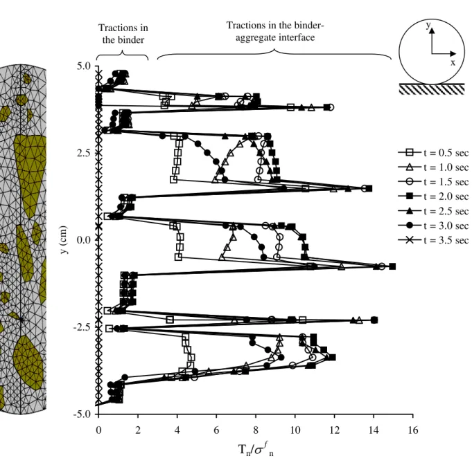
Finally, Figure 6 shows the predicted normalized normal tractions (Tn/σfn) along the
diameter of the specimen for the 0.8mm/sec displacement rate at selected times. It is particularly interesting to note the traction concentrations that occur at the binder-aggregate interfaces. Therefore, this model is capable of accounting for variations in mixture makeup such as particle size, shape and orientation.
and damage accumulation in viscoelastic media, such as asphaltic mixtures. It is important to note that, even though it has not been considered herein, this approach can also account for permanent deformation due to both binder viscous flow (by setting E∞ = 0) and viscoplastic
behavior (by utilizing a viscoplastic constitutive model for the bulk binder).
Furthermore, the approach outlined can be applied along with homogenization techniques in a multiscale scheme in order to predict asphalt pavement response in the actual structure subjected to mechanical and thermal loading. Thus, the analysis can be performed on different scales wherein the microscopic mechanisms, such as microcracking, damage accumulation and healing, can be evaluated at the smaller scales and included into the larger scale through homogenization principles.
5. CONCLUSIONS
Investigations in asphaltic mixtures have typically not taken into account the heterogeneity of the material at the scale of the aggregate and asphaltic cement. The paper herein presents the sequel to a study that attempts to address this issue by using a micromechanics approach to investigate crack growth in asphaltic mixtures. The improvement incorporated was the consideration of the viscoelastic behavior of the bulk asphalt binder and a micromechanical viscoelastic cohesive zone model capable of accounting for both damage evolution and crack growth in viscoelastic media through the introduction of ductility at the crack tip. The numerical results were compared to experimental results obtained from the IDT test wherein monotonically increasing displacements are applied to the specimen. Although the current study has considered crack growth only under monotonically increasing loading, the technique may also be applied to fatigue loading, which is the next step in this research effort.
ACKNOWLEDGEMENTS
The authors thank the group of the Laboratory of Pavement Mechanics at Universidade Federal do Ceará – LMP/UFC. The first, second and fourth authors are thankful to CNPq-Brazil for their respective research support. Thanks are also due to Felipe Freitas for the mixture preparation, the digitalization of the specimen cross section, and his overall comments.
REFERENCES
1. Monismith, C.L., Epps, J.A. and Finn, F.N. Improved asphalt mix design. Proceedings, Association of Asphalt Paving Technologists, Vol. 54, pp. 347-406, 1985.
2. La Roche, C. and Riviere, N. Fatigue behavior of asphalt mixes: influence of laboratory test procedures on fatigue performances. Eighth International Conference on Asphalt Pavements, Seattle, Washington, USA, pp. 899-917, 1997.
3. Jayawickrama, P.W. and Lytton, R. Methodology for predicting asphalt concrete overlay life against reflection cracking. Sixth International Conference on the Structural Design of Asphalt Pavements, Vol. I, 912-924, 1987.
4. Perng, J-D. Analysis of crack propagation in asphalt concrete using a cohesive crack model. PhD Dissertation, Ohio State University, 1989.
5. Erkens, S.M.J.G., Moraal, J., Molenaar, A., Groenendijk, J. and Jacobs, M. Using Paris´ Law to determine fatigue characteristics – A discussion. Eighth International Conference on Asphalt Pavements, Seattle, Washington, USA, pp. 1123-1140, 1997.
6. Owusu-Antwi, E., Khazanovich, L. and Titus-Glover, L. A mechanistic-based model for predicting reflective cracking in AV overlaid pavements. 77th Annual Meeting, Transportation Research Board, 1998. 7. Lytton, R.L., Uzan, J., Fernando, E.G., Roque, R., Hiltunen, D. and Stoffels, S.M. Development and
validation of performance prediction models and specifications for asphalt binders and paving mixes. Strategic Highway Research Program, National Research Council, 1993.
8. Little, D.N., Lytton, R.L., Williams, D. and Kim, Y.R. Propagation and healing of microcracks in asphalt concrete and their contribution to fatigue. Asphalt Science and Technology, edited by Artur M. Usmani, Indianapolis, Indiana, Marcel Dekker, Inc, 1997.
9. Kim, Y.R., Lee, H-J. and Little D. Fatigue characterization of asphalt concrete using viscoelasticity and continuum damage theory. Proceedings, Association of Asphalt Paving Technologists, Vol. 66, pp. 520-558 1997.
10. Lee, H-J. and Kim, Y.R. Viscoelastic constitutive model for asphalt concrete under cyclic loading. Journal of Engineering Mechanics, Vol. 124, No. 1, pp.32-40, 1998.
11. Daniel, J.S. and Kim, Y.R. Development of a simplified fatigue test and analysis procedure using a viscoelastic continuum damage model. Proceedings, Association of Asphalt Paving Technologists, Vol. 72, 2002.
12. Chang, K.G. and Meegoda, J.N. Micromechanical simulation of hot mix asphalt. Journal of Engineering Mechanics, Vol. 123, No. 5, May, pp. 495-503, 1997.
13. Guddati, M.N., Feng, Z. and Kim, Y.R. Towards a micromechanics-based procedure to characterize fatigue performance of asphalt concrete. 2002 TRB Annual Meeting CD-ROM, 2001.
14. Soares, J.B., Freitas, F.A.C. and Allen, D.H. Crack modeling of asphaltic mixtures considering heterogeneity of the material. 2003 TRB Annual meeting CD-ROM, 2002.
15. Sadd, M.II., Dai, Q., Parameswaran, V. and Shukla, A. Simulation of asphalt materials using a finite element micromechanical model with damage mechanics. 2003 TRB Annual meeting CD-ROM, 2002. 16. Soranakom, C., Birgisson, B., Napier, J.A.L and Roque, R. Simulation of fracture initiation in hot asphalt
mixtures. 2003 TRB Annual Meeting CD-ROM, 2002.
17. Goodrich, J.L. Asphaltic Binder rheology, asphalt concrete rheology and asphalt concrete mix properties. Proceedings, Association of Asphalt Paving Technologists, AAPT, v. 60, p. 80-120, 1991.
18. Park, S.W., Kim, Y.R. and Schapery, R.A. A viscoelastic continuum damage model and its application to uniaxial behavior of asphalt concrete. Mechanics of Materials, v. 24, p. 241-255, 1996.
20. Souza, F.V. and Soares, J.B. Previsão do comportamento mecânico de misturas asfálticas a partir dos resultados do ensaio de creep estático (in Portuguese). Proceedings, XVI Congresso de Pesquisa e Ensino em Transportes, ANPET, Brazil, p. 29-41, 2002.
21. Kim, Y.R. and Little, D. One-dimensional constitutive modeling of asphalt concrete. Journal of Engineering Mechanics, Vol. 116, No. 4, pp. 751-772, 1990.
22. Zhao, Y. and Kim, Y.R. The time-temperature superposition for asphalt mixtures with growing damage and permanent deformation in compression. 2003 TRB Annual Meeting CD-ROM, 2002.
23. Souza, F.V. and Soares, J.B. Efeito da Consideração do Comportamento Viscoelástico Linear do Revestimento no Cálculo de Tensões e Deslocamentos em Pavimentos Asfálticos (in Portuguese). Proceedings, XVII Congresso de Pesquisa e Ensino em Transportes, ANPET, Brazil, 2003.
24. Schapery, R.A. A theory of crack initiation and growth in viscoelastic media – Part I, Part II, Part III.
International Journal of Fracture 11 (1, 3, 4), 141-159, 369-387, 549-562, 1975.
25. Schapery, R.A. Correspondence principles and a generalized J-integral for large deformation and fracture analysis of viscoelastic media. International Journal of Fracture, v. 25, p. 195-223, 1984.
26. Schapery, R.A. On the mechanics of crack closing and bonding in linear viscoelastic media. International Journal of Fracture 39, pp. 163-189, 1989.
27. Yoon, C. and Allen, D.H. Damage dependent constitutive behavior and energy release rate for a cohesive zone in thermoviscoelastic solid. International Journal of Fracture 96, pp.55-74, 1999.
28. Allen, D.H. and Searcy, C.R. A micromechanical model for a viscoelastic cohesive zone. International Journal of Fracture 107, pp. 159-176, 2001.
29. Schapery, R.A. Mechanical characterization and analysis of inelastic composite laminates with growing damage. Mech. Comp. Mat. and Structures, ASME AMD 100, pp. 1-9, 1989.
30. Schapery, R.A. Simplifications in the behavior of viscoelastic composites with growing damage. Proceedings, IUTAM Symposium in inelastic deformation of composite materials, New York, pp. 193-214, 1990.
31. Park, S.W. and Schapery, R.A. A viscoelastic constitutive model for particulate composites with growing damage. Int. J. Solids Structures 8 (34), pp.931-947, 1997.
32. Ha, K. and Schapery, R.A. A three-dimensional viscoelastic constitutive model for particulate composites with growing damage and its experimental validation. Int. J. Solids Structures 26-27 (35), pp. 3497-3517, 1998.
33. Allen, D.H, Jones, R.H. and Boyd, J.G. Micromechanical analysis of a continuous fiber metal matrix composite including the effects of matrix viscoplasticity and evolving damage. Journal of the Mechanics and Physics of Solids 42 (3), pp. 505-529, 1994.
34. Allen, D.H., Lo, D.C. and Zocher, M.A. Modeling of damage evolution in laminated viscoelastic composites. International Journal of Damage Mechanics 6, pp. 5-22.
35. Allen, D.H. and Searcy, C.R. Numerical aspects of a micromechanical model of a cohesive zone. Journal of Reinforced Plastics and Composites 19 (3), pp. 240-248, 2000.
36. Searcy, C.R. A model for predicting the degradation of mechanical properties in heterogeneous viscoelastic media due to multiscale fracture. PhD Dissertation, Texas A&M University, 2003.
37. Soares, J.B., Allen, D.H., Melo, L.T.B. and Cavalcante Neto, J.B. Local and global finite element modeling of asphaltic pavements. Proceedings, Third International Symposium: 3-D Finite Element for Pavement, Analysis, Design and Research, 2002.
38. Huang, Y.H. Pavement analysis and design. Englewood Cliffs, NJ: Prentice Hall, 1993.
39. Allen, D.H. Homogenization principles and their application to continuum damage mechanics. Composites Science and Technology 61, pp. 2223-2230, 2001.
40. Allen, D.H. and Yoon, C. Homogenization techniques for thermoviscoelastic solids containing cracks. Int. J. Solids Structures 35 (31-32), pp. 4035-4053, 1998.
41. Allen, D.H., Harris C.E., and Groves, S.E. A thermomechanical constitutive theory for elastic composites with distributed damage – Part I: Theoretical development and Part II: Application to matrix cracking in laminated composites. Int. J. Solids Structures 23, No. 9, pp. 1301-1318, 1319-1338, 1987.
42. Lee, J.W., Allen, D.H. and Harris, C.E. The upper bounds of reduced axial and shear moduli in cross-ply laminates with matrix cracks. Composite Materials: Fatigue and Fracture (Third Volume), ASTM STP 1110, T.K. O´Brien, Ed., American Society for Testing and Materials, Philadelphia, pp. 56-69, 1991.
44. Griffith, A.A. The phenomena of rupture and flow in solids. Philosophical Transactions of the Royal Society of London, Series A 221, pp. 163-198, 1921.
45. Dugdale, D. Yielding of steel sheets containing slits. Journal of Mechanics and Physics of Solids, Volume 8, pp. 100-104, 1960.
46. Barenblatt, G.I. Mathematical theory of equilibrium cracks in brittle fracture. Advances in Applied Mechanics, Volume 7, pp. 55-129, Academic Press, New York, 1962.
47. Jenq, Y-S. and Perng, J-D. Analysis of crack propagation in asphalt concrete using cohesive crack model.
Transportation Research Record 1317, pp. 90-99, 1991.
48. Costanzo, F. and Allen, D.H. A continuum mechanics approach to some problems in subcritical crack propagation. International Journal of Fracture 63, pp. 27-57, 1994.
49. Williams, J., Two experiments for measuring specific viscoelastic cohesive zone parameters. Master’s Thesis, Texas A&M University, 2002.
50. Zocher, M.A., Allen, D.H. and Groves, S.E. A three-dimensional finite element formulation for thermoviscoelastic orthotropic media. International Journal for Numerical Methods in Engineering 40, pp. 2267-2288, 1997.
51. Foulk, J.W., Allen, D.H. and Helms, K.L.E. Formulation of a three-dimensional cohesive zone model for application to a finite element algorithm. Computational Methods in Applied Mechanics and Engineering
183, pp. 51-66, 2000.
52. Soares, J.B. Concrete characterization through fracture mechanics and selected pavement applications. PhD Dissertation, Texas A&M University, College Station, TX, 1997.
53. Phillips, M.L., Yoon, C. and Allen, D.H. A computational model for predicting damage evolution in laminated composite plates. Journal of Engineering Materials and Technology, 1999.
54. DNER. Especificações gerais para obras rodoviárias do DNER, ES 313/97 (in Portuguese). Volume III/IV, Pavimentos Flexíveis. Departamento Nacional de Estradas de Rodagem, 1997.
LIST OF TABLES
TABLE 1 Prony series terms for binder relaxation modulus
LIST OF FIGURES
FIGURE 1 Finite element mesh
FIGURE 2 Damage parameter α1× applied displacement rate
FIGURE 3 Sensitivity analysis with respect to α1 and m parameters (a) α1-sensitivity of the force-displacement curve; (b) m-sensitivity of the force-displacement curve; (c) α1 -sensitivity of the averaged damage and (d) m-sensitivity of the averaged damage
FIGURE 4 (a) Numerical simulation × experiment and simulated crack propagation (for 0.8mm/sec) at times: (b) 2.0sec; (c) 2.5sec; (d) 3.0sec and (e) 3.5sec
FIGURE 5 (a) Force-pseudo displacement curves; (b) Averaged damage × applied diametral displacement; (c) Averaged damage × pseudo displacement
TABLE 1 Prony series terms for binder relaxation modulus
i Relaxation modulus
Ei (MPa) ρi (seconds)
∞ 5.736E+01 -
1 2.328E+01 1.098E+06
2 3.456E+01 2.307E+04
3 6.432E+01 1.056E+03
4 1.625E+02 1.440E+02
5 2.460E+02 1.300E+01
6 6.082E+03 1.050E+00
7 4.488E+03 1.500E-01
8 5.947E+03 1.600E-02
9 6.744E+03 2.900E-04
0.0 0.5 1.0 1.5 2.0 2.5 3.0 3.5
0.0 0.5 1.0 1.5 2.0 2.5 3.0 3.5
Displacement rate (mm/sec)
D
ama
ge
pa
ra
me
te
r
α
10 2 4 6 8 10 12 14
0.0 0.8 1.6 2.4 3.2 4.0
Displacement (mm)
For
ce (kN)
α1 = 0.4 α1 = 0.5 α1 = 0.6 α1 = 0.4
α1 = 0.5
α1 = 0.6
0 2 4 6 8 10 12 14
0.0 0.8 1.6 2.4 3.2 4.0
Displacement (mm)
Fo
rc
e (k
N)
m = 0.05
m = 0.10
m = 0.15
(a) (b)
0.0 0.1 0.2 0.3 0.4 0.5 0.6 0.7 0.8 0.9 1.0
0.0 0.8 1.6 2.4 3.2 4.0
Displacement (mm) A v er aged D a m age
α1 = 0.4 α1 = 0.5 α1 = 0.6
α1 = 0.4
α1 = 0.5
α1= 0.6
0.0 0.1 0.2 0.3 0.4 0.5 0.6 0.7 0.8 0.9 1.0
0.0 0.8 1.6 2.4 3.2 4.0
Displacement (mm) Av e ra g e d Da m a g e
m = 0.05 m = 0.10
m = 0.15
(c) (d)
FIGURE 3 Sensitivity analysis with respect to α1 and m parameters (a) α1-sensitivity of
the force-displacement curve; (b) m-sensitivity of the force-displacement curve; (c) α1
0 2 4 6 8 10 12 14 16 18 20
0.0 0.5 1.0 1.5 2.0 2.5 3.0 3.5
Displacement (mm)
F
o
rce (
k
N)
Numerical Experimental
0.8mm/sec 1.6mm/sec
3.2mm/sec
(a)
(b) (c)
(d) (e)
FIGURE 4 (a) Numerical simulation × experiment and simulated crack propagation (for 0.8mm/sec) at times: (b) 2.0sec; (c) 2.5sec; (d) 3.0sec and (e) 3.5sec
b c d
0 2 4 6 8 10 12 14 16 18 20
0.00 0.10 0.20 0.30 0.40 0.50
Pseudo Displacement (mm)
Fo rc e (k N) Numerical Experimental 0.8mm/sec 1.6mm/sec 3.2mm/sec (a) 0.0 0.1 0.2 0.3 0.4 0.5 0.6 0.7 0.8 0.9 1.0
0.0 0.5 1.0 1.5 2.0 2.5 3.0
Displacement (mm) Aver aged Damage 0.8mm/sec 1.6mm/sec 3.2mm/sec (b) 0.0 0.1 0.2 0.3 0.4 0.5 0.6 0.7 0.8 0.9 1.0
0.00 0.10 0.20 0.30 0.40 0.50
Pseudo Displacement (mm)
A v er ag ed D am age 0.8mm/sec 1.6mm/sec 3.2mm/sec (c)
-5.0 -2.5 0.0 2.5 5.0
0 2 4 6 8 10 12 14 16
Tn/σ f
n
y (
cm)
t = 0.5 sec t = 1.0 sec t = 1.5 sec t = 2.0 sec t = 2.5 sec t = 3.0 sec t = 3.5 sec
FIGURE 6 Predicted normalized normal tractions × location at selected times for the 0.8mm/sec displacement rate
x y Tractions in
the binder
Tractions in the binder-aggregate interface